Siemens SIMATIC ET 200SP IM 155-6 DP HF Manual
Interface module
Hide thumbs
Also See for SIMATIC ET 200SP IM 155-6 DP HF:
- Manual (57 pages) ,
- Equipment manual (100 pages)
Table of Contents
Advertisement
Advertisement
Table of Contents

Subscribe to Our Youtube Channel
Related Manuals for Siemens SIMATIC ET 200SP IM 155-6 DP HF


Summary of Contents for Siemens SIMATIC ET 200SP IM 155-6 DP HF
- Page 2 ___________________ Preface ___________________ Guide to documentation ___________________ SIMATIC Product overview ___________________ Connecting ET 200SP Interface module IM 155-6 DP HF ___________________ (6ES7155-6BA01-0CN0) Parameters/address space ___________ Interrupts, error messages, diagnostics and system Manual alarms ___________________ Compatibility ___________________ Technical specifications ___________________ Dimension drawing 10/2018 A5E03916550-AD...
- Page 3 Note the following: WARNING Siemens products may only be used for the applications described in the catalog and in the relevant technical documentation. If products and components from other manufacturers are used, these must be recommended or approved by Siemens. Proper transport, storage, installation, assembly, commissioning, operation and maintenance are required to ensure that the products operate safely and without any problems.
-
Page 4: Preface
Purpose of the documentation This manual supplements the ET 200SP distributed I/O system (http://support.automation.siemens.com/WW/view/en/58649293) system manual. Functions that generally relate to the system are described in this manual. The information provided in this manual and in the system/function manuals supports you in commissioning the ET 200SP distributed I/O system. - Page 5 Siemens' products and solutions undergo continuous development to make them more secure. Siemens strongly recommends that product updates are applied as soon as they are available and that the latest product versions are used. Use of product versions that are no longer supported, and failure to apply the latest updates may increase customers' exposure to cyber threats.
-
Page 6: Table Of Contents
Table of contents Preface ..............................3 Guide to documentation .......................... 7 Product overview ..........................12 Properties ..........................12 Functions ..........................14 2.2.1 Functions ..........................14 2.2.2 Configuration control ....................... 16 Connecting ............................17 Terminal assignment ....................... 17 Block diagram ......................... 19 Setting the PROFIBUS DP address .................. - Page 7 Table of contents Compatibility ............................49 Compatibility of modules ......................49 Technical specifications ........................52 Technical specifications ......................52 Dimension drawing ..........................55 Interface module IM 155-6 DP HF (6ES7155-6BA01-0CN0) Manual, 10/2018, A5E03916550-AD...
-
Page 8: Guide To Documentation
Guide to documentation The documentation for the SIMATIC ET 200SP distributed I/O system is arranged into three areas. This arrangement enables you to access the specific content you require. Basic information The system manual describes in detail the configuration, installation, wiring and commissioning of the SIMATIC ET 200SP. - Page 9 You need to register once to use the full functionality of "mySupport". You can find "mySupport" in the Internet (https://support.industry.siemens.com/My/ww/en). "mySupport" - Documentation In the Documentation area of "mySupport", you have the possibility to combine complete manuals or parts of them to make your own manual.
- Page 10 ● Manuals, characteristics, operating manuals, certificates ● Product master data You can find "mySupport" - CAx Data in the Internet (http://support.industry.siemens.com/my/ww/en/CAxOnline). Application examples The application examples support you with various tools and examples for solving your automation tasks. Solutions are shown in interplay with multiple components in the system - separated from the focus in individual products.
- Page 11 You can find the SIMATIC Automation Tool on the Internet (https://support.industry.siemens.com/cs/ww/en/view/98161300). PRONETA With SIEMENS PRONETA (PROFINET network analysis), you analyze the plant network during commissioning. PRONETA features two core functions: ● The topology overview independently scans PROFINET and all connected components.
- Page 12 Guide to documentation SINETPLAN SINETPLAN, the Siemens Network Planner, supports you in planning automation systems and networks based on PROFINET. The tool facilitates professional and predictive dimensioning of your PROFINET installation as early as in the planning stage. In addition, SINETPLAN supports you during network optimization and helps you to exploit network resources optimally and to plan reserves.
-
Page 13: Product Overview
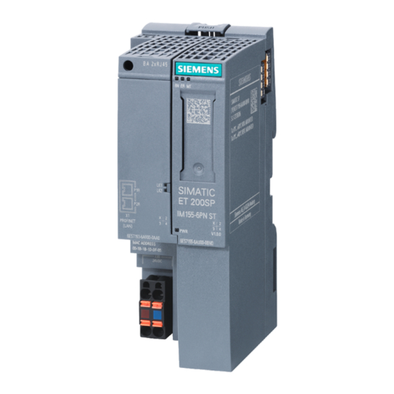
Product overview Properties Article number 6ES7155-6BA01-0CN0 Article number 6ES7155-6BA01-0CN0 contains the following components: ● Interface module IM 155-6 DP HF (6ES7155-6BU01-0CN0) ● Server module (6ES7193-6PA00-0AA0) ● PROFIBUS FastConnect bus connector (6ES7972-0BB70-0XA0) View of the module Figure 2-1 View of the 155-6 DP HF interface module with supplied accessories Interface module IM 155-6 DP HF (6ES7155-6BA01-0CN0) Manual, 10/2018, A5E03916550-AD... - Page 14 ● Labeling strips ● Reference identification label You can find additional information on the accessories in the ET 200SP distributed I/O system (http://support.automation.siemens.com/WW/view/en/58649293) system manual. Server module The server module is included in the product package of the interface module and available separately as an accessory.
-
Page 15: Functions
IM 155-6 DP HF interface module as of 6ES7155-6BA00-0CN0 in DPV1 mode with more than 244 bytes of parameter data. Configuration with the GSD file does not offer this option. Reference You can find additional information on identification data in the ET 200SP distributed I/O system (http://support.automation.siemens.com/WW/view/en/58649293) system manual. Functions 2.2.1 Functions... - Page 16 STEP 7 as of STEP 7 (TIA as of with GSD file V5.5 SP3 with Portal) as of (http://support.a HSP0242 utoma- tion.siemens.co m/WW/view/en/ 19698639/1300 00) / software from a third- party manufac- turer Operation after Y-link (not with V1.1.0 F-modules) Hot-swapping V1.0.0...
-
Page 17: Configuration Control
Reference You can find more information on configuration control ● in the ET 200SP distributed I/O system (http://support.automation.siemens.com/WW/view/en/58649293) system manual ● on the Internet under the following link: Application collection (http://support.automation.siemens.com/WW/view/en/29430270) ● in the STEP 7 online help. -
Page 18: Connecting
Connecting Terminal assignment 24 V DC supply voltage The table below shows the signal names and descriptions of the pin assignment of the 24 V DC supply voltage. Table 3- 1 Pin assignment 24 V DC supply voltage View Signal name Description Connector IM connection... - Page 19 Supply plus (from station) RxD/TxD-N Data line A Reference You can find additional information on connecting the interface module and on the accessories in the ET 200SP distributed I/O system (http://support.automation.siemens.com/WW/view/en/58649293) system manual. Interface module IM 155-6 DP HF (6ES7155-6BA01-0CN0) Manual, 10/2018, A5E03916550-AD...
-
Page 20: Block Diagram
Connecting 3.2 Block diagram Block diagram The following figure show the block diagram of the IM 155-6 DP HF interface module. ① ET 200SP backplane bus interface and electronics 24 V DC supply voltage ② Backplane bus Ground ③ Internal power supply RUN/STOP LED (green) X80 24 Feed supply voltage... -
Page 21: Setting The Profibus Dp Address
Connecting 3.3 Setting the PROFIBUS DP address Setting the PROFIBUS DP address Introduction On the interface module (PROFIBUS), set the PROFIBUS DP address for PROFIBUS DP using the DIP switch. By setting the PROFIBUS DP address, you specify where the ET 200SP is to be addressed on the PROFIBUS DP. -
Page 22: Parameters/Address Space
Parameters/address space Parameters Parameters for IM 155-6 DP HF interface module The following table shows the parameters for the IM 155-6 DP HF interface module. Table 4- 1 Parameters for IM 155-6 DP HF interface module (GSD file) Parameters Value range Default Effective range Configuration control... -
Page 23: Description Of Parameters
196 from the user program so that the ET 200SP distributed I/O system can operate the I/O modules. Reference You can find additional information in the ET 200SP distributed I/O system (http://support.automation.siemens.com/WW/view/en/58649293) system manual and in the STEP 7 online help. Interface module IM 155-6 DP HF (6ES7155-6BA01-0CN0) Manual, 10/2018, A5E03916550-AD... -
Page 24: Startup When Expected/Actual Config Differ
Parameters/address space 4.2 Description of parameters 4.2.2 Startup when expected/actual config differ If the parameter is enabled and ● modules are removed and inserted during operation, this does not lead to a station failure of the ET 200SP distributed I/O system. ●... -
Page 25: Substitute Value Behavior
Parameters/address space 4.3 Substitute value behavior Substitute value behavior The substitute value behavior is implemented by the DP master per slot in the ET 200SP distributed I/O system. The respective output reacts according to its configured substitute value behavior: ● Current-free/voltage-free ●... -
Page 26: Interrupts, Error Messages, Diagnostics And System Alarms
Interrupts, error messages, diagnostics and system alarms Status and error displays LED displays The figure below shows the LED display on the interface module: ① RN (green) ② ER (red) ③ MT (yellow) ④ DP (green) ⑤ PWR (green) Figure 5-1 LED displays on the interface module Meaning of the LED displays The following tables contain the meaning of the status and error displays. - Page 27 I/O module. Not relevant Not relevant Maintenance is demanded. Perform maintenance Hardware or firmware faulty. Run a firmware update. If the error persists, contact Siemens Industry Flashes Flashes Flashes Online Support. Replace the interface module. PWR LED On (on interface module): Check the backplane bus for a short-circuit.
- Page 28 Interrupts, error messages, diagnostics and system alarms 5.1 Status and error displays PWR LED on the interface module Table 5- 2 Status display of the PWR LED PWR LED Meaning Remedy No or too little supply voltage Check the supply voltage. Supply voltage present LED DP on the RS485 interface Table 5- 3...
- Page 29 Interrupts, error messages, diagnostics and system alarms 5.1 Status and error displays Operating principle The LED error display provides information on the cause of the error. After a notification by means of a flashing signal, the error type and then the error location/error code are displayed in each case.
-
Page 30: Interrupts
Interrupts, error messages, diagnostics and system alarms 5.2 Interrupts Interrupts 5.2.1 Introduction Definition The interrupt section of the slave diagnostics indicates the interrupt type and the event that led to an interrupt being triggered. The interrupt section comprises 62 bytes including an interrupt header. - Page 31 Interrupts, error messages, diagnostics and system alarms 5.2 Interrupts Data record The diagnostic data of a module are located in the data records 0 and 1: ● Data record 0 contains 4 bytes of diagnostics data that describe the current status of the distributed I/O system.
- Page 32 Interrupts, error messages, diagnostics and system alarms 5.2 Interrupts Reading data records DS0 and DS1 can be read with SFC 59 (RD_REC) or SFB 52 (RDREC). The data length of DS 1 can be up to 240 bytes. In this case, DS1 includes up to 38 channel error entries. Note the figures below in this section.
- Page 33 Interrupts, error messages, diagnostics and system alarms 5.2 Interrupts Structure of interrupts The figure below shows the structure of the interrupt section for the ET 200SP distributed I/O system: Figure 5-3 Structure of the interrupt status of the interrupt section Interface module IM 155-6 DP HF (6ES7155-6BA01-0CN0) Manual, 10/2018, A5E03916550-AD...
- Page 34 Interrupts, error messages, diagnostics and system alarms 5.2 Interrupts Diagnostic interrupt, byte x+4 to x+7 The figure below shows the structure starting at byte x+4 to x+7 for diagnostic interrupt: Figure 5-4 Structure of bytes x+4 to x+7 for diagnostic interrupt Interface module IM 155-6 DP HF (6ES7155-6BA01-0CN0) Manual, 10/2018, A5E03916550-AD...
- Page 35 Interrupts, error messages, diagnostics and system alarms 5.2 Interrupts Diagnostic interrupt from the modules, starting at byte x+8 The figure below shows the structure starting at byte x+8: Figure 5-5 Structure starting at byte x+8 Diagnostic interrupt from the modules, starting at byte x+14 The channel error entries start from byte x+14.
- Page 36 Interrupts, error messages, diagnostics and system alarms 5.2 Interrupts The following table is used to explain the channel error entries: Description Channel number 0 to 63: Channel number for channel error 0x8000: Entire submodule Channel properties Bit 0 to 7 : Free data type : bit : 2 bit...
- Page 37 Interrupts, error messages, diagnostics and system alarms 5.2 Interrupts Example of a diagnostic interrupt The figure below shows an example of a diagnostic interrupt (part 1): Figure 5-7 Example of a diagnostic interrupt (part 1) Interface module IM 155-6 DP HF (6ES7155-6BA01-0CN0) Manual, 10/2018, A5E03916550-AD...
- Page 38 Interrupts, error messages, diagnostics and system alarms 5.2 Interrupts The figure below shows an example of a diagnostic interrupt (part 2): Figure 5-8 Example of a diagnostic interrupt (part 2) Hardware interrupt of digital and analog input modules The figure below shows the structure starting at byte x+4 for the hardware interrupt: Figure 5-9 Structure starting at byte x+4 for hardware interrupt Interface module IM 155-6 DP HF (6ES7155-6BA01-0CN0)
-
Page 39: Evaluating Interrupts Of Et 200Sp
Interrupts, error messages, diagnostics and system alarms 5.2 Interrupts 5.2.2 Evaluating interrupts of ET 200SP Introduction With certain process statuses/errors, the DP slave in each case creates an interrupt block with the corresponding information in the diagnostics frame (DPV1 interrupt mechanism). Regardless of this, the diagnostic status of the DP slave is displayed in the identifier-related diagnostics, in the module status, and in the channel diagnostics. -
Page 40: Alarms
Interrupts, error messages, diagnostics and system alarms 5.3 Alarms Alarms Actions after a diagnostics alarm in DPV1 mode The error is entered in the channel diagnostics in the diagnostics frame: ● In DPV1 mode, diagnostics can be reported as diagnostic interrupts. ●... -
Page 41: Slave Diagnostics
Interrupts, error messages, diagnostics and system alarms 5.3 Alarms 5.3.1 Slave diagnostics The figure below shows the structure of the slave diagnostics. Figure 5-10 Structure of the slave diagnostics Note The length of the diagnostics frame varies with the IM 155-6 DP HF (depending on parameter assignment) between 6 and 244 bytes in DPV1 mode. -
Page 42: Station Statuses 1 To 3
Interrupts, error messages, diagnostics and system alarms 5.3 Alarms 5.3.2 Station statuses 1 to 3 Station statuses 1 to 3 provide an overview of the status of a DP slave. Structure of station status 1 (byte 0) Table 5- 7 Structure of station status 1 (byte 0) Meaning Cause/Remedy... -
Page 43: Master Profibus Address
Interrupts, error messages, diagnostics and system alarms 5.3 Alarms Structure of station status 2 (byte 1) Table 5- 8 Structure of station status 2 (byte 1) Meaning 1: The DP slave parameters need to be reassigned. 1: A diagnostics alarm is present. The DP slave will not operate until the problem is eliminated (static diagnostics alarm). -
Page 44: Identifier-Related Diagnostics
Interrupts, error messages, diagnostics and system alarms 5.3 Alarms 5.3.4 Identifier-related diagnostics The identifier-related diagnostics indicates whether modules of the ET 200SP distributed I/O system have errors or not. Identifier-related diagnostics start at byte 6 and comprise 8 bytes. The figure below shows how the identifier-related diagnostics for the ET 200SP distributed I/O system is structured with the IM 155-6 DP HF interface module: Figure 5-11 Structure of the identifier-related diagnostics... -
Page 45: Module Status
Interrupts, error messages, diagnostics and system alarms 5.3 Alarms 5.3.5 Module status The module status indicates the status of the configured modules and provides more information on the identifier-related diagnostics with respect to the configuration. The module status begins after the identifier-related diagnostics and comprises 17 bytes. The following figure shows how the module status for the ET 200SP distributed I/O system is structured with the IM 155-6 DP HF interface module: Figure 5-12... -
Page 46: Channel Diagnostics
Interrupts, error messages, diagnostics and system alarms 5.3 Alarms 5.3.6 Channel diagnostics Channel diagnostics provides information about channel errors in modules and details of the identifier-related diagnostics. Channel diagnostics begins after the module status. Channel diagnostics does not affect the module status. The following figure shows how the channel diagnostics for the ET 200SP distributed I/O system is structured with the IM 155-6 DP HF interface module: Figure 5-13... -
Page 47: H Status
Interrupts, error messages, diagnostics and system alarms 5.3 Alarms 5.3.7 H status Requirements The H status in the diagnostics frame supplies the IM 155-6 DP HF interface module only when operated behind a Y link (e.g. IM 157) in DPV1 mode. This block can be passed over during the evaluation of the diagnostics frame. -
Page 48: Invalid Configuration States Of The Et 200Sp On Profibus Dp
Interrupts, error messages, diagnostics and system alarms 5.3 Alarms 5.3.8 Invalid configuration states of the ET 200SP on PROFIBUS DP Incorrect configuration states The following incorrect configuration states of the ET 200SP distributed I/O system lead to a failure of the DP slave or prevent the start of data exchange. ●... -
Page 49: Load Voltage Failure On The Baseunit Bu
Interrupts, error messages, diagnostics and system alarms 5.3 Alarms 5.3.9 Load voltage failure on the BaseUnit BU...D Load voltage failure If supply voltage fails on the BaseUnit BU...D, the I/O modules react as follows: ● A remove module interrupt is generated if an I/O module is removed during the failure of the supply voltage. -
Page 50: Compatibility
Compatibility Compatibility of modules Valid firmware versions The table below lists the valid firmware versions and their field of application for the I/O modules. I/O modules Firmware version Comment DI 8x24VDC ST V1.0.1 As of this version, you have the option to oper- ate I/O modules after an IM 155-6 DP HF DI 16x24VDC ST (6ES7155-6BA00-0CN0) interface module. - Page 51 Compatibility 6.1 Compatibility of modules Plugging and pulling (hot-swapping) of ET 200SP I/O modules NOTICE Pulling and plugging (hot swapping) of ET 200SP I/O modules during operation on S7-300 via PROFIBUS DP ET 200SP I/O modules can be pulled and plugged: •...
- Page 52 Compatibility 6.1 Compatibility of modules First BaseUnit of an ET 200SP in the configuration The interface modules support plugging a dark-colored BaseUnit in slot 1. This means that modules without a connection to the integrated voltage buses P1 and P2 can now also be configured starting with slot 1.
-
Page 53: Technical Specifications
Technical specifications Technical specifications of the IM 155-6 DP HF The following table shows the technical specifications as of 08/2018. You can find a data sheet including daily updated technical specifications on the Internet (https://support.industry.siemens.com/cs/de/en/pv/6ES7155-6BA01-0CN0/td?dl=de). Article number 6ES7155-6BA01-0CN0 General information... - Page 54 Technical specifications 7.1 Technical specifications Article number 6ES7155-6BA01-0CN0 Address area Address space per module 32 byte; per input / output Address space per module, max. • Address space per station 244 byte; per input / output Address space per station, max. •...
- Page 55 Technical specifications 7.1 Technical specifications Article number 6ES7155-6BA01-0CN0 between backplane bus and electronics between PROFIBUS DP and all other circuit components between supply and all other circuits Permissible potential difference between different circuits Safety extra low voltage SELV Isolation Isolation tested with 707 V DC (type test) Ambient conditions Ambient temperature during operation...
-
Page 56: Dimension Drawing
Dimension drawing This appendix contains a dimension drawing of the module installed on a mounting rail. Always observe the specified dimensions for installation in cabinets, control rooms, etc. Figure A-1 Dimension drawing of the IM 155-6 DP HF interface module (front and side view) Interface module IM 155-6 DP HF (6ES7155-6BA01-0CN0) Manual, 10/2018, A5E03916550-AD...
Need help?
Do you have a question about the SIMATIC ET 200SP IM 155-6 DP HF and is the answer not in the manual?
Questions and answers