Siemens SIMATIC ET 200SP IM 155-6 PN/2 HF Manual
Interface module
Hide thumbs
Also See for SIMATIC ET 200SP IM 155-6 PN/2 HF:
- Manual (56 pages) ,
- Equipment manual (100 pages)
Table of Contents
Advertisement
Advertisement
Table of Contents

Related Manuals for Siemens SIMATIC ET 200SP IM 155-6 PN/2 HF


Summary of Contents for Siemens SIMATIC ET 200SP IM 155-6 PN/2 HF
- Page 2 ___________________ Preface ___________________ Guide ___________________ SIMATIC Product overview ___________________ Wiring ET 200SP Interface module IM 155-6 PN/2 HF ___________________ (6ES7155-6AU01-0CN0) Parameters/address space ___________ Interrupts, error messages, diagnostics and system Manual alarms ___________________ Compatibility ___________________ Technical specifications ___________________ Dimension drawing 10/2018 A5E03915895-AH...
- Page 3 Note the following: WARNING Siemens products may only be used for the applications described in the catalog and in the relevant technical documentation. If products and components from other manufacturers are used, these must be recommended or approved by Siemens. Proper transport, storage, installation, assembly, commissioning, operation and maintenance are required to ensure that the products operate safely and without any problems.
-
Page 4: Preface
Purpose of the documentation This manual supplements the ET 200SP distributed I/O system (http://support.automation.siemens.com/WW/view/en/58649293) system manual. Functions that generally relate to the system are described in this manual. The information provided in this manual and in the system/function manuals supports you in commissioning the ET 200SP distributed I/O system. - Page 5 Siemens' products and solutions undergo continuous development to make them more secure. Siemens strongly recommends that product updates are applied as soon as they are available and that the latest product versions are used. Use of product versions that are no longer supported, and failure to apply the latest updates may increase customers' exposure to cyber threats.
-
Page 6: Table Of Contents
Table of contents Preface ..............................3 Guide ..............................7 Product overview ..........................12 Properties ..........................12 Functions ..........................16 2.2.1 Device replacement ........................ 20 2.2.2 Real-time communication ....................... 21 2.2.3 Isochronous real-time communication ..................21 2.2.4 Prioritized startup ........................22 2.2.5 Submodules .......................... - Page 7 Table of contents Interrupts, error messages, diagnostics and system alarms ..............35 Status and error displays ....................... 35 Interrupts ..........................38 5.2.1 Triggering of a diagnostics interrupt..................39 5.2.2 Triggering a hardware interrupt....................39 5.2.3 Triggering of a remove/insert module interrupt ..............40 Alarms ............................
-
Page 8: Guide
Guide The documentation for the SIMATIC ET 200SP distributed I/O system is arranged into three areas. This arrangement enables you to access the specific content you require. Basic information The system manual describes in detail the configuration, installation, wiring and commissioning of the SIMATIC ET 200SP. - Page 9 You need to register once to use the full functionality of "mySupport". You can find "mySupport" in the Internet (https://support.industry.siemens.com/My/ww/en). "mySupport" - Documentation In the Documentation area of "mySupport", you have the possibility to combine complete manuals or parts of them to make your own manual.
- Page 10 ● Manuals, characteristics, operating manuals, certificates ● Product master data You can find "mySupport" - CAx Data in the Internet (https://support.industry.siemens.com/my/ww/en/CAxOnline). Application examples The application examples support you with various tools and examples for solving your automation tasks. Solutions are shown in interplay with multiple components in the system - separated from the focus in individual products.
- Page 11 You can find the SIMATIC Automation Tool on the Internet (https://support.industry.siemens.com/cs/ww/en/view/98161300). PRONETA With SIEMENS PRONETA (PROFINET network analysis), you analyze the plant network during commissioning. PRONETA features two core functions: ● The topology overview independently scans PROFINET and all connected components.
- Page 12 Guide SINETPLAN SINETPLAN, the Siemens Network Planner, supports you in planning automation systems and networks based on PROFINET. The tool facilitates professional and predictive dimensioning of your PROFINET installation as early as in the planning stage. In addition, SINETPLAN supports you during network optimization and helps you to exploit network resources optimally and to plan reserves.
-
Page 13: Product Overview
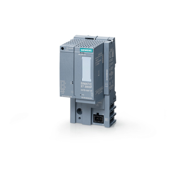
Product overview Properties Article number 6ES7155-6AU01-0CN0 View of the module Figure 2-1 View of the AS interface module 155-6 PN/2 HF with included accessory (24 V DC connector and server module) and optional accessories (labeling strips and reference identification label) Interface module IM 155-6 PN/2 HF (6ES7155-6AU01-0CN0) Manual, 10/2018, A5E03915895-AH... - Page 14 Product overview 2.1 Properties Properties The module has the following technical properties: ● Connects the ET 200SP distributed I/O system with PROFINET IO. ● Power supply 1 L+ 24 V DC (SELV/PELV). The connection plug is included in the scope of delivery of the interface module and is available as replacement part.
- Page 15 Information on the BusAdapters is available in the BusAdapter (https://support.industry.siemens.com/cs/ww/en/view/109751716) manual. You can find more information on accessories in the ET 200SP distributed I/O system (http://support.automation.siemens.com/WW/view/en/58649293) system manual. Server module The server module is included in the scope of delivery of the interface module and available separately as an accessory.
- Page 16 65. You can find more information in the Server module (http://support.automation.siemens.com/WW/view/en/63257531) manual. First BaseUnit of an ET 200SP in the configuration The interface modules support plugging a dark-colored BaseUnit in slot 1. This means that modules without a connection to the integrated voltage buses P1 and P2 can now also be configured starting with slot 1.
-
Page 17: 2.2 Functions
Product overview 2.2 Functions Functions Introduction The interface module supports the following PROFINET IO functions: ● Integrated switch with 2 ports ● Supported Ethernet services: PING, ARP, SNMP, LLDP ● Port diagnostics ● Disabling ports ● Minimum update time 250 µs ●... - Page 18 GSD file V5.5 SP3 V5.5 SP4 with Portal) as of as of as of (http://support.auto with HSP 233 HSP 250/255 V12.0.1 with mation.siemens.co HSP 0058 m/WW/view/en/19 698639/130000)/s oftware from a third-party manu- facturer Real-time communication V2.0.0 Isochronous real-time V2.0.0...
- Page 19 GSD file V5.5 SP3 V5.5 SP4 with Portal) as of as of as of (http://support.auto with HSP 233 HSP 250/255 V12.0.1 with mation.siemens.co HSP 0058 m/WW/view/en/19 698639/130000)/s oftware from a third-party manu- facturer BA SCRJ/RJ45 V3.1.0 X (as of V5.5...
- Page 20 I/O modules during operation. For more information on compatibility, refer to section: Compatibility (Page 48) See also ET 200SP distributed I/O system (http://support.automation.siemens.com/WW/view/en/58649293) PROFINET with STEP 7 (http://support.automation.siemens.com/WW/view/en/49948856) Interface module IM 155-6 PN/2 HF (6ES7155-6AU01-0CN0) Manual, 10/2018, A5E03915895-AH...
-
Page 21: Device Replacement
If the IO devices were already used in another configuration, reset them to factory settings before reusing them. You can find information on this in the system manual ET 200SP distributed I/O system (http://support.automation.siemens.com/WW/view/en/58649293). You can find more information on this topic in the STEP 7 online help and ●... -
Page 22: Real-Time Communication
STEP 7 online help and ● As of STEP 7 (TIA Portal) V12, in the function manual PROFINET with STEP 7 (http://support.automation.siemens.com/WW/view/en/49948856). ● As of STEP 7 V5.5, in the system manual PROFINET System Description (http://support.automation.siemens.com/WW/view/en/19292127). -
Page 23: Prioritized Startup
You can find more information on this topic in the STEP 7 online help and ● As of STEP 7 (TIA Portal) V12, in the function manual PROFINET with STEP 7 (http://support.automation.siemens.com/WW/view/en/49948856). ● As of STEP 7 V5.5, in the system manual PROFINET System Description (http://support.automation.siemens.com/WW/view/en/19292127). -
Page 24: Media Redundancy (Mrp)
You can find more information on this topic in the STEP 7 online help and ● As of STEP 7 V12, in the function manual PROFINET with STEP 7 (http://support.automation.siemens.com/WW/view/en/49948856). ● As of STEP 7 V5.5, in the system manual PROFINET System Description (http://support.automation.siemens.com/WW/view/en/19292127). -
Page 25: Isochronous Mode
You can find additional information in the STEP 7 online help and ● As of STEP 7 V12, in the PROFINET with STEP 7 (http://support.automation.siemens.com/WW/view/en/49948856) function manual. ● As of STEP 7 V5.5, in the system manual PROFINET System Description (http://support.automation.siemens.com/WW/view/en/19292127). -
Page 26: System Redundancy S2
● Docking station ● Docking unit You can find additional information in the STEP 7 online help and ● As of STEP 7 V12, in the PROFINET with STEP 7 (http://support.automation.siemens.com/WW/view/en/49948856) function manual 2.2.12 Oversampling Oversampling The IM 155-6 PN/2 HF interface module supports the oversampling mode of HS modules. -
Page 27: Value Status
● Function manual PROFINET as of STEP 7 V12 (http://support.automation.siemens.com/WW/view/en/49948856) ● System manual PROFINET System Description (http://support.automation.siemens.com/WW/view/en/19292127) ● PROFIenergy (http://support.automation.siemens.com/WW/view/en/66928686) product information ● Internet (http://www.profibus.com) under Common Application Profile PROFIenergy; Technical Specification for PROFINET; Version 1.0; January 2010; Order No: 3.802... -
Page 28: Configuration Control (Option Handling)
Properties The IM 155-6 PN/2 HF interface module supports the use of fail-safe modules. Reference You can find more information in the ET 200SP distributed I/O system (http://support.automation.siemens.com/WW/view/en/58649293) system manual. 2.2.17 Multi Hot Swap Properties You can remove and insert any number of I/O modules during operation. The interface module and the inserted I/O modules remain in operation. -
Page 29: Module-To-Module Communication (Mtm)
Product overview 2.2 Functions 2.2.18 Module-to-Module Communication (MtM) Introduction Module-to-Module Communication (MtM) offers the following advantages: ● Improved performance during transmission of data by bypassing the IO controller. ● Deterministic cycle times ● Cost-effective, high-performance solutions for applications where the performance of a specific technology module is not required. -
Page 30: Setting The Time
Setting the time The interface module supports time setting, for example with AI Energy Meter 480VAC/CT HF (6ES7134-6PA00-0CU0). We show you how to set the time in an application example (https://support.automation.siemens.com/WW/view/en/109754890). Interface module IM 155-6 PN/2 HF (6ES7155-6AU01-0CN0) Manual, 10/2018, A5E03915895-AH... -
Page 31: Wiring
1L+ and 2L+ as well as 1M and 2M are bridged internally. Maximum 10 A permitted. Reference You can find more information on accessories and how to connect the interface module in the ET 200SP distributed I/O system (http://support.automation.siemens.com/WW/view/en/58649293) system manual. Interface module IM 155-6 PN/2 HF (6ES7155-6AU01-0CN0) Manual, 10/2018, A5E03915895-AH... -
Page 32: Block Diagram
Wiring 3.2 Block diagram Block diagram Block diagram The following figure shows the block diagram of the IM 155-6 PN/2 HF interface module. ① Switch 24 V DC supply voltage ② ET 200SP backplane bus interface and elec- Ground tronics ③... -
Page 33: Parameters/Address Space
I/O modules. Reference You can find more information on the control data record in the ET 200SP distributed I/O system (http://support.automation.siemens.com/WW/view/en/58649293) system manual and in the STEP 7 online help. Interface module IM 155-6 PN/2 HF (6ES7155-6AU01-0CN0) Manual, 10/2018, A5E03915895-AH... -
Page 34: Diagnostics (Maintenance) Undervoltage
Parameters/address space 4.3 Substitute value behavior 4.2.2 Diagnostics (maintenance) undervoltage Diagnostics (maintenance) undervoltage Diagnostics (maintenance) undervoltage is triggered if the supply voltage falls below the value 19.2 V DC. When the supply voltage then exceeds 20.4 V DC, the diagnostics alarm is reported as outgoing. -
Page 35: Status Of The Supply Voltage L+ Of The I/O Modules
IM 155-6 PN/2 HF. You can find information on the status of the supply voltage L+ of the I/O modules in the Server module (http://support.automation.siemens.com/WW/view/en/63257531) manual. Interface module IM 155-6 PN/2 HF (6ES7155-6AU01-0CN0) Manual, 10/2018, A5E03915895-AH... -
Page 36: Interrupts, Error Messages, Diagnostics And System Alarms
Interrupts, error messages, diagnostics and system alarms Status and error displays LED displays The following figure shows the LED displays on the interface module and BusAdapter. ① RN (green) ② ER (red) ③ MT (yellow) ④ PWR (green) ⑤ MT2 (yellow), SCRJ port ⑥... - Page 37 Hardware or firmware defective (LEDs Run a firmware update. If the error persists, LK1 and LK2 of the PROFINET inter- contact Siemens Industry Online Support. face do not flash). Replace the interface module. * PWR LED on (on the interface module): Check the backplane bus for a short-circuit.
- Page 38 Interrupts, error messages, diagnostics and system alarms 5.1 Status and error displays PWR LED on the interface module Table 5- 2 Status display of the PWR LED PWR LED Meaning Solution Supply voltage not present or too small. Check the supply voltage. Supply voltage present.
-
Page 39: Interrupts
Interrupts, error messages, diagnostics and system alarms 5.2 Interrupts Error display Table 5- 4 Error display Error type Error location Cause of error Solution (MAINT) (ERROR/ MAINT) Check the configuration No server module • of the ET 200SP. Interruptions on the backplane bus •... -
Page 40: Triggering Of A Diagnostics Interrupt
Independent of the cyclic user program, alarms are made available on the display of the S7- 1500 CPU, the CPU web server and the HMI device. You will find more information on system diagnostics in the Diagnostics (https://support.industry.siemens.com/cs/ww/en/view/59192926) function manual. 5.2.1 Triggering of a diagnostics interrupt Triggering of a diagnostics interrupt For an incoming or outgoing event (e.g. -
Page 41: Triggering Of A Remove/Insert Module Interrupt
Interrupts, error messages, diagnostics and system alarms 5.2 Interrupts 5.2.3 Triggering of a remove/insert module interrupt Triggering of a remove/insert module interrupt In the event of a remove/insert module interrupt, the CPU interrupts processing of the user program and processes the remove/insert module OB, e.g. OB 83. The event that triggered the interrupt is entered in the start information of the remove/insert module OB. -
Page 42: Alarms
Additional information on the data records for PROFINET IO The structure of the diagnostic data records and programming examples are available in the programming manual From PROFIBUS DP to PROFINET IO (http://support.automation.siemens.com/WW/view/en/19289930) and in Example application (http://support.automation.siemens.com/WW/view/en/24000238). Interface module IM 155-6 PN/2 HF (6ES7155-6AU01-0CN0) -
Page 43: Maintenance Events
5.3 Alarms Causes of error and troubleshooting The causes of error and remedies for the diagnostic alarms are described in the manuals for I/O modules (http://support.automation.siemens.com/WW/view/en/55679691/133300) in the section, "Interrupts, error messages, and system events". See also Channel diagnostics (Page 43) 5.3.2... -
Page 44: Channel Diagnostics
Interrupts, error messages, diagnostics and system alarms 5.3 Alarms 5.3.3 Channel diagnostics Function Channel-related diagnostics provides information about channel faults in modules. Channel faults are mapped as channel diagnostics data in IO diagnostics data records. The data record is read using the instruction "RDREC". Structure of the diagnostics data records The data records supported by the ET 200SP distributed I/O system are based on the standard PROFINET IO - Application Layer Service Definition V2.2. - Page 45 Interrupts, error messages, diagnostics and system alarms 5.3 Alarms Structure of the manufacturer-specific diagnostics data records (IM 155-6 PN HF Version < V3.3) The structure of the diagnostics data records is differentiated by the BlockVersion. The following BlockVersion applies to the IM 155-6 PN HF interface modules: Table 5- 7 Structure of the manufacturer-specific diagnostics data records IM 155-6 PN HF interface module...
- Page 46 Interrupts, error messages, diagnostics and system alarms 5.3 Alarms USI structure = W#16#0004 Table 5- 10 USI structure = W#16#0004 Data block name Content Comment Bytes W#16#0004 Manufacturer-specific diagnostics with missing server module Result: Station stop The I/O modules fail → substitute value behavior •...
-
Page 47: Invalid Configuration States Of The Et 200Sp On Profinet Io
Interrupts, error messages, diagnostics and system alarms 5.3 Alarms USI structure = W#16#0007 Table 5- 12 USI structure = W#16#0007 Data block name Content Comment Bytes W#16#0007 Manufacturer-specific diagnostics if operation is not possi- ble with existing bus configuration Result: Station stop The I/O modules fail →... -
Page 48: Failure Of Supply Voltage L+ At Baseunit Bu
Interrupts, error messages, diagnostics and system alarms 5.3 Alarms See also Status and error displays (Page 35) Channel diagnostics (Page 43) 5.3.5 Failure of supply voltage L+ at BaseUnit BU...D Failure of the supply voltage L+ The I/O modules react as follows to failure of the supply voltage L+ on the BaseUnit BU...D: ●... -
Page 49: Compatibility
Compatibility Compatibility of modules Compatibility with the IM 155-6 PN/2 HF interface module If you exchange or replace an interface module, the following table shows the compatibilities: ● Between the interface modules IM 155-6 PN/2 HF and IM 155-6 PN ST ●... - Page 50 Compatibility 6.1 Compatibility of modules The table below shows all modules that do not support a station configuration with more than 32 I/O modules: Table 6- 1 Incompatible modules with functional status Modules Article number Up to functional status Analog modules AI 4xI 2-/4-wire ST 6ES7134-6GD00-0BA1 AI 4xU/I 2-wire ST...
- Page 51 Compatibility 6.1 Compatibility of modules Required tools 3 to 3.5 mm screwdriver (for resetting via the RESET button) Procedure 1. Remove the interface module from the mounting rail and swivel it downwards. 2. The RESET button is located on the back of the interface module behind a small opening: Push a screwdriver into the small opening, thus pressing the RESET button.
- Page 52 Compatibility 6.1 Compatibility of modules Interface module IM 155-6 PPN HF (6ES7155-6AU00-0CN0) with version V4.2 Note You cannot use the following functions during operation of the IM 155-6 PN HF (6ES7155-6AU00-0CN0) with firmware version V4.2: • Module-to-Module Communication (MtM) • Setting the time •...
-
Page 53: Technical Specifications
Technical specifications Technical specifications of the IM 155-6 PN/2 HF The following table shows the technical specifications as of 08/2018. You will find a data sheet including daily updated technical specifications on the Internet (https://support.industry.siemens.com/cs/de/en/pv/6ES7155-6AU01-0CN0/td?dl=en). Article number 6ES7155-6AU01-0CN0 General information... - Page 54 Technical specifications Article number 6ES7155-6AU01-0CN0 Input current Current consumption, max. 700 mA Inrush current, max. 4.5 A I²t 0.25 A²·s Power loss Power loss, typ. 2.4 W Address area Address space per module 288 byte; For input and output data respectively Address space per module, max.
- Page 55 Technical specifications Article number 6ES7155-6AU01-0CN0 Protocols PROFINET IO Device Services Yes; Bus cycle time: min. 250 µs – Isochronous mode – Open IE communication Yes; 250 μs, 500 μs, 1 ms, 2 ms, 4 ms additional- – ly with IRT with high performance: 250 µs to 4 ms in 125 µs frame –...
- Page 56 Technical specifications Article number 6ES7155-6AU01-0CN0 Yes; green PWR LED Monitoring of the supply voltage (PWR- • LED) Yes; 2x green link LEDs on BusAdapter Connection to network LINK (green) • Potential separation between backplane bus and electronics between PROFINET and all other circuits between supply and all other circuits Isolation Isolation tested with...
-
Page 57: Dimension Drawing
Dimension drawing This appendix contains a dimension drawing of the module mounted on a mounting rail. Always observe the specified dimensions for installation in cabinets, control rooms, etc. Figure A-1 Dimension drawing of the IM 155-6 PN/2 HF interface module, front and side views Interface module IM 155-6 PN/2 HF (6ES7155-6AU01-0CN0) Manual, 10/2018, A5E03915895-AH...
Need help?
Do you have a question about the SIMATIC ET 200SP IM 155-6 PN/2 HF and is the answer not in the manual?
Questions and answers