Sign In
Upload
Manuals
Brands
Siemens Manuals
Control Unit
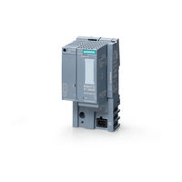
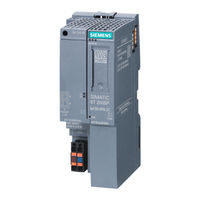
SIMATIC ET 200SP IM 155-6 PN/2 HF
Siemens SIMATIC ET 200SP IM 155-6 PN/2 HF Manuals
Manuals and User Guides for Siemens SIMATIC ET 200SP IM 155-6 PN/2 HF. We have
3
Siemens SIMATIC ET 200SP IM 155-6 PN/2 HF manuals available for free PDF download: Equipment Manual, Manual
Siemens SIMATIC ET 200SP IM 155-6 PN/2 HF Equipment Manual (100 pages)
Interface module
Brand:
Siemens
| Category:
Control Unit
| Size: 1 MB
Table of Contents
Legal Information
3
Table of Contents
4
Introduction
7
200SP Documentation Guide
8
Basic Information
8
Device Information
8
General Information
9
Product Information
9
SIMATIC Technical Documentation
10
Application Examples
11
Tool Support
12
Multifieldbus Configuration Tool (MFCT)
13
Industrial Cybersecurity
14
Introduction to Industrial Cybersecurity
14
Cybersecurity Information
14
Cybersecurity-Relevant Information
15
Product Overview
17
Properties
17
Maximum Configuration
18
Server Module
20
Multifieldbus Engineering
21
Detect Active Fieldbus
21
Profinet Io
22
PROFINET IO Functions
22
Supported Ethernet Services: ICMP, ARP, SNMP, LLDP
25
Port Diagnostics
26
Disabling of Ports
26
Isochronous Real-Time Communication
26
Minimum Update Time 250 Μs
27
Prioritized Startup
27
Isochronous Mode
27
Device Replacement Without Programming Device (PG) and Without Topological Config
28
Reset to Factory Settings Via PROFINET IO
29
Identification Data I&M0 to I&M4
29
Firmware Update Via PROFINET IO
30
Media Redundancy (MRP and MRPD)
30
Shared Device
31
Distribution of Module Channels to Submodules
31
Module-Internal or Submodule-Internal Shared Input/Shared Output (MSI/MSO)
32
System Redundancy S2
32
Value Status (Quality Information, QI) of I/O Modules
33
Profienergy
33
Removal/Insertion of Multiple I/O Modules During Operation (Multi Hot Swap)
33
Module-To-Module Communication (Mtm)
34
Setting the Time
35
Time Distribution
35
Use of Fail-Safe Modules
35
Configuration Control (Option Handling)
36
Reading out Service Data
36
Reference Temperature Distribution
36
Diagnostic Interrupts
37
Hardware Interrupts
37
Maintenance Events
37
Interface Local Coupling of IO Data
38
Alternating IO Devices During Operation ("Docking Systems")
39
Interrupts, Error Messages, Diagnostics and System Alarms
40
Status and Error Displays
40
Operating Principle
43
Error Display
43
Interrupts
44
Triggering of a Diagnostics Interrupt
44
Triggering a Hardware Interrupt
45
Triggering of a Remove/Insert Module Interrupt
45
Triggering of a Maintenance Event
45
Alarms
46
Diagnostic Messages
46
Maintenance Alarms
48
Invalid Configuration States of the et 200SP System
51
Failure of Supply Voltage L+ at Baseunit BU
51
STOP of the IO Controller and Recovery of the IO Device
52
Ethernet/Ip
53
Ethernet/Ip Functions
53
Applicable Modules with Ethernet/Ip
55
Technology Modules
56
Communication Modules
56
Update Time of the I/O Data
56
Examples for I/O Data Mapping
57
I/O Data Mapping Introduction Ethernet/Ip
57
Example of I/O Data Mapping for I/O Data Alignment Byte
59
Example Configuration
59
Input Buffer
60
Output Buffer
60
Example of I/O Data Mapping for I/O Data Alignment Word
61
Example of I/O Data Mapping for Flexible Data Alignment
63
MF Shared Device
65
Diagnostics
66
Status and Error Displays for Ethernet/Ip
66
Modbus TCP
69
Modbus TCP Functions
69
Applicable Modules with Modbus TCP
71
Update Time of the I/O Data
73
Examples for I/O Data Mapping
73
I/O Data Mapping Introduction Modbus
73
Configuration Example
75
Example of I/O Data Mapping for I/O Data Alignment Byte
75
Example of I/O Data Mapping for I/O Data Alignment Word
77
MF Shared Device
79
Diagnostics
80
Status and Error Displays for Modbus TCP
80
Wiring
83
Pin Assignment
83
Block Diagram
84
Parameters/Address Space
85
Parameters
85
Explanation of Parameters
86
Diagnostics: Undervoltage
86
Configuration Control
86
I/O Data Alignment
87
Connection Hold Time
87
Hold Time after Connection Reset
87
Type of Fieldbus
87
Substitute Value Behavior
88
Status of the Supply Voltage L+ of the I/O Modules
88
Compatibility
89
Compatibility of Modules
89
Operation and Maintenance
92
Resetting an Interface Module to Factory Settings Via the RESET Button
92
Resetting Interface Module with MFCT to Factory Settings
92
Firmware Update
93
Technical Specifications
94
Dimension Drawing
100
Advertisement
Siemens SIMATIC ET 200SP IM 155-6 PN/2 HF Manual (57 pages)
Interface module
Brand:
Siemens
| Category:
Control Unit
| Size: 1 MB
Table of Contents
Preface
4
Table of Contents
6
1 Guide
8
2 Product Overview
13
Properties
13
2.2 Functions
17
Device Replacement
21
Real-Time Communication
22
Isochronous Real-Time Communication
22
Prioritized Startup
23
Submodules
23
Media Redundancy (MRP)
24
Shared Device
24
Isochronous Mode
25
Module-Internal Shared Input/Shared Output (MSI/MSO)
25
System Redundancy S2
26
Alternating IO Devices During Operation ("Docking Systems")
26
Oversampling
26
Value Status
27
Profienergy
27
Configuration Control (Option Handling)
28
Use of Fail-Safe Modules
28
Multi Hot Swap
28
Module-To-Module Communication (Mtm)
29
Setting the Time
30
3 Wiring
31
Pin Assignment
31
Block Diagram
32
4 Parameters/Address Space
33
Parameters
33
Explanation of Parameters
33
Enable Configuration Control
33
Diagnostics (Maintenance) Undervoltage
34
Substitute Value Behavior
34
Status of the Supply Voltage L+ of the I/O Modules
35
5 Interrupts, Error Messages, Diagnostics and System Alarms
36
Status and Error Displays
36
Interrupts
39
Triggering of a Diagnostics Interrupt
40
Triggering a Hardware Interrupt
40
Triggering of a Remove/Insert Module Interrupt
41
Alarms
42
Diagnostics Alarms
42
Maintenance Events
43
Channel Diagnostics
44
Invalid Configuration States of the ET 200SP on PROFINET IO
47
Failure of Supply Voltage L+ at Baseunit BU
48
STOP of the IO Controller and Recovery of the IO Device
48
6 Compatibility
49
Compatibility of Modules
49
7 Technical Specifications
53
Dimension Drawing
57
Siemens SIMATIC ET 200SP IM 155-6 PN/2 HF Manual (56 pages)
Interface module
Brand:
Siemens
| Category:
Control Unit
| Size: 2 MB
Table of Contents
Preface
4
Table of Contents
6
1 Guide to Documentation
8
2 Product Overview
13
Properties
13
Functions
15
Configuration Control
17
3 Connecting
18
Terminal Assignment
18
Block Diagram
20
Setting the PROFIBUS DP Address
21
4 Parameters/Address Space
22
Parameters
22
Description of Parameters
23
Configuration Control
23
Startup When Expected/Actual Config Differ
24
Diagnostic Interrupt
24
Hardware Interrupt
24
Insert/Remove Module Interrupt
24
Substitute Value Behavior
25
5 Interrupts, Error Messages, Diagnostics and System Alarms
26
Status and Error Displays
26
Interrupts
30
Introduction
30
Evaluating Interrupts of ET 200SP
39
Triggering of a Diagnostics Interrupt
39
Triggering a Hardware Interrupt
39
Triggering an Insert/Remove Module Interrupt
39
Alarms
40
Slave Diagnostics
41
Station Statuses 1 to 3
42
Master PROFIBUS Address
43
Identifier-Related Diagnostics
44
Module Status
45
Channel Diagnostics
46
H Status
47
Invalid Configuration States of the ET 200SP on PROFIBUS DP
48
Load Voltage Failure on the Baseunit BU
49
6 Compatibility
50
Compatibility of Modules
50
7 Technical Specifications
53
Dimension Drawing
56
Advertisement
Advertisement
Related Products
Siemens SIMATIC ET 200SP HA
Siemens ET 200eco PN M12-L
Siemens ET 200S 1SI
Siemens SIMATIC ET 200MP IM 155-5 PN HF
Siemens ET 200eco PN Master
Siemens SIPLUS ECC8000
Siemens SIMATIC ET 200SP TM ECC 2xPWM ST
Siemens EVF4U20E Series
Siemens EVG4U10E015
Siemens EVG4U10E035
Siemens Categories
Industrial Equipment
Control Unit
Controller
Oven
Washer
More Siemens Manuals
Login
Sign In
OR
Sign in with Facebook
Sign in with Google
Upload manual
Upload from disk
Upload from URL