Advertisement
Quick Links
Advertisement

Related Manuals for Dahua DH-VTO9341D


Summary of Contents for Dahua DH-VTO9341D
- Page 1 Face Recognition Apartment Outdoor Station User's Manual V1.0.0...
-
Page 2: Cybersecurity Recommendations
Cybersecurity Recommendations Important The following functions are for reference only. Some series products may not support all the functions listed below. Mandatory actions to be taken towards cybersecurity Change Passwords and Use Strong Passwords: The number one reason systems get "hacked" is due to having weak or default passwords. It is recommended to change default passwords immediately and choose a strong password whenever possible. - Page 3 Only forward the HTTP and TCP ports that you need to use. Do not forward a huge range of numbers to the device. Do not DMZ the device's IP address. You do not need to forward any ports for individual cameras if they are all connected to ...
-
Page 4: Regulatory Information
Regulatory Information The regulatory information herein might vary according to the model you purchased. Some information is only applicable for the country or region where the product is sold. FCC Information Changes or modifications not expressly approved by the party responsible for compliance could void the user's authority to operate the equipment. -
Page 5: Foreword
Foreword General This Manual introduces the function, structure, networking, mounting process, configuration process, WEB interface operation, and technical parameters of the device. Safety Instructions The following categorized signal words with defined meaning might appear in the Manual. Signal Words Meaning Indicates a high potential hazard which, if not avoided, will result DANGER in death or serious injury. - Page 6 We are not liable for any loss caused by the operations that do not comply with the Manual. The Manual would be updated according to the latest laws and regulations of related regions. For detailed information, see the paper manual, CD-ROM, QR code or our official website.
-
Page 7: Important Safeguards And Warnings
Important Safeguards and Warnings The following description is the correct application method of the device. Please read the manual carefully before use, in order to prevent danger and property loss. Strictly conform to the manual during application and keep it properly after reading. Electrical safety ... -
Page 8: Table Of Contents
Table of Contents Cybersecurity Recommendations ......................II Regulatory Information ........................... IV Foreword ..............................V Important Safeguards and Warnings ....................VII 1 Introduction ............................1 General............................1 Features ............................1 2 Appearance ............................3 Dimension ............................. 3 Front Panel ............................ 3 Rear Panel ............................ - Page 9 6.4.1 Face Registration ......................35 6.4.2 Fingerprint Registration ....................39 6.4.3 Issuing Card ........................43 Viewing Function ......................... 46 6.5.1 Viewing Face Data ......................46 6.5.2 Viewing Fingerprint ......................49 6.5.3 Viewing Card Information ....................53 Configuring VTO Parameter ....................... 53 6.6.1 Engineering Interface .......................
- Page 10 7.10.2 Adding single IPC ......................83 7.10.3 Import Config ........................84 7.10.4 Export Config ........................84 7.11 Publish Information........................84 7.11.1 Send Info ......................... 85 7.11.2 History Info ........................85 7.12 UPnP Config ..........................86 7.12.2 Enabling UPnP ....................... 86 7.12.3 Adding Service ........................
-
Page 11: Introduction
Introduction General This face recognition apartment outdoor station (hereinafter referred to be "the VTO") can be connected to the video intercom home station (VTH), video intercom master station (VTS), and servers to constitute a video intercom system, which supports video call between visitors and residents. - Page 12 Fingerprint Adding Add data of up to 3,000 fingerprints to the VTO or add them in batch from the server to realize fingerprint unlock. Alarm Supports various alarms, including tamper alarm, door contact alarm, and duress password alarm. The alarm will also be sent to the management center. Information Publishing The VTO can send information to multiple VTH devices.
-
Page 13: Appearance
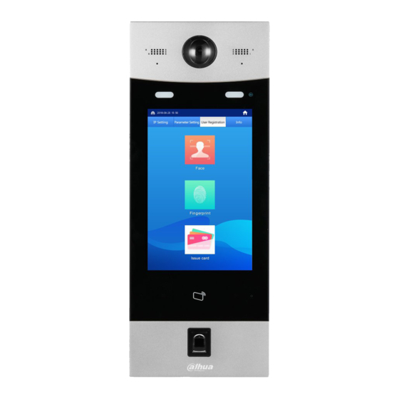
Appearance Dimension See Figure 2-1 for the dimension. Figure 2-1 Dimension(unit: mm) Front Panel See Figure 2-2 for the front panel, and for the detailed description, see Table 2-1. Appearance 3... - Page 14 Figure 2-2 Front panel Table 2-1 Front panel description Name Description Monitors door area, and recognizes face Camera information. Speaker Outputs audio. Light sensor Detects ambient lighting condition. Provides extra light when recognizing faces. Fill light Provides extra light to the camera during dark condition.
-
Page 15: Rear Panel
Rear Panel See Figure 2-3 for the rear panel, and for the detailed description, see Table 2-2. Figure 2-3 Rear panel Table 2-2 Rear panel description Name Description Camera angle Pull up or down to adjust camera angle. adjusting knob The VTO would make alarm sound if it is being Tamper alarm removed from the wall by force, and the alarm will... -
Page 16: Door Lock Port
2.3.1 Door Lock Port This port can be used to connect to door locks, and the connection method varies with different locks. For the detailed information, see Figure 2-4, Figure 2-5, and Figure 2-6. Figure 2-4 Electro-mechanical lock connection Figure 2-5 Magnetic lock connection Appearance 6... -
Page 17: Rs485 Port
Figure 2-6 Electronic lock connection 2.3.2 RS485 Port This port can be used to connect to 485 devices. For the detailed connection method, see Figure 2-7. Figure 2-7 485 devices connection 2.3.3 Wiegand Port This port is reserved, which includes one set of input port and one set of output port. The Wiegand input port can connect to the Wiegand card reader, and the Wiegand output port can connect to the access controller. -
Page 18: Alarm-In Port
Figure 2-8 Wiegand input/output connection 2.3.4 Alarm-in Port There are two alarm-in ports, which can connect to two alarm input devices. See Figure 2-9. Figure 2-9 Alarm input device connection 2.3.5 Alarm-out Port There are two alarm-out ports, which can connect to two alarm output devices. See Figure 2-10. - Page 19 Figure 2-10 Alarm output device connection Appearance 9...
-
Page 20: Network Diagram
Network Diagram See Figure 3-1 for the network diagram of the VTO. Figure 3-1 Network diagram Network Diagram 10... -
Page 21: Installing The Vto
Installing the VTO Installation Requirement Do not install the VTO to places with condensation, high temperature, grease or dust, chemical corrosion, direct sunlight, or zero shelter. The installation and adjustment must be finished by professional crew, and do not ... - Page 22 Keep the center of the VTO at 1.4 m to 1.6 m above the ground. Step 1 Attach the VTO to the mounting box with the screw. Step 2 Cut an opening with the size of the mounting box on the wall, and then put the mounting box and the VTO in the opening.
-
Page 23: Configuring Devices
Configuring Devices This chapter introduces how to make basic configurations and realize network connection, calling, and monitoring. Before configuration, make sure the following works are finished. Make sure there is no short circuit or open circuit in the circuits, and then power up the ... - Page 24 Figure 5-1 Password setting Step 3 Enter and confirm the password, and then click Next. The Email setting interface is displayed. See Figure 5-2. This password is to login the Web interface, and it should contain at least 8 digits and at least two types from number, letter, and symbol.
- Page 25 Figure 5-3 Device succeed Step 6 Click OK. The login interface is displayed. See Figure 5-4 Figure 5-4 Login Step 7 Enter the username and the password, and then click Login. The default username is admin. The password is what you configured during initialization. ...
- Page 26 Step 2 Enter the IP address, subnet mask, and default gateway you planned, and then click The VTO will reboot after modification, and then there might be two conditions. If the PC IP address is within the planned network segment, the login interface with ...
- Page 27 Figure 5-7 SIP server config If the VTO you are visiting works as SIP server Select SIP Server Enable, and then click OK. The VTO reboots, and then the login interface is displayed. After logging in, the Device Manager will display in the menu. You need to add VTO and VTH then.
- Page 28 Parameter Description Username Leave to the default. Password SIP Domain Leave it blank or keep the default. Login UserName The username and password of the SIP server. Login PWD If third party server is configured as SIP server, see the manual of the server for the detailed configuration.
- Page 29 Parameter Description IP Address The IP address of the VTO. Username The username and password for the Web interface of the VTO. Password Step 5 Click OK to finish configuration. Do the operation above repeatedly to add more VTO devices in the network. 5.1.1.6 Adding VTH If there are master VTH and extension VTH being used, you need to add them all.
-
Page 30: Configuring Vth
Parameter Description number you planned for the VTH. If there are master VTH and extension VTH being used, the short number of the master VTH should be "room number#0", and the extension VTH to be #1, #2, and #3 and so on. Register Password Leave to the default. - Page 31 Figure 5-13 Main interface 5.1.2.2 Configuring VTH Network Make sure the VTH is in the same network segment with the VTO, otherwise the VTH cannot get information from the VTO. Step 1 In the main interface, press and hold Setting until the Password Verification dialog box displays.
- Page 32 Figure 5-15 Network (2) Step 4 Configure network with different access modes. Enter the IP address, subnet mask, and gateway, and then click OK; Tap enable DHCP and acquire IP address automatically. If the VTH has wireless function, tap WLAN to configure network. ...
- Page 33 Figure 5-17 Wireless IP 5.1.2.3 VTH Config You can configure room number, VTH type, and Master IP. Step 1 In the main interface, press and hold Setting until the Password Verification dialog box displays. Step 2 Enter the password you configured during initialization, and then tap OK. Step 3 Tap VTH Config.
- Page 34 Tap Master, and then the VTH type changes to Extension. Enter the room number (such as 9901#1), the IP address of the master VTH, master name, and the master password. The master name and the master password are the username and password of the master VTH.
- Page 35 Parameter Description If VTO works as SIP server, the Domain should be VDP. User Name The username and password of the SIP server. Login Pwd Step 5 Set the Enable Status to The SIP server function is enabled. Step 6 Tap OK to save.
-
Page 36: Verifying Configuration
Verifying Configuration 5.2.1 Calling VTH from VTO Step 1 Enter the room number of the VTH on the VTO. Step 2 Tap Call. The "Calling now, please wait a moment" voice notice comes up, and then the calling request lasts for 30 s. See Figure 5-21. Figure 5-21 Calling the VTH Step 3... -
Page 37: Doing Monitor From Vth
Step 4 on the VTH to answer the call. The VTO is in the phone call state. See Figure 5-23, and the configuration succeeded. Figure 5-23 Phone call state 5.2.2 Doing monitor from VTH You can monitor the area that VTO covers from VTH. Step 1 In the main interface of the VTH, select Monitor >... - Page 38 Figure 5-25 Monitor screen Configuring Devices 28...
-
Page 39: Operating Vto
Operating VTO This chapter introduces the functions of the VTO, including calling residents, unlock, adding and searching face/fingerprint/access card, system configuration, and information searching. Main interface The main interface is displayed after booting. See Figure 6-1. For the detailed description, see Table 6-1. -
Page 40: Call Function
Call Function 6.2.1 Calling VTH Step 1 Enter the room number of the VTH on the VTO. Step 2 Tap Call. The "Calling now, please wait a moment" voice notice comes up, and then the calling request lasts for 30 s. See Figure 6-2. Figure 6-2 Calling VTH Step 3... -
Page 41: Calling Property (Management Center)
Step 4 on the VTH to answer the call. The VTO is in the phone call state. See Figure 6-4. Figure 6-4 Phone call state 6.2.2 Calling Property (management center) Step 1 Tap Property on the VTO; or enter the number of the management center, and then tap Call. - Page 42 Figure 6-5 Calling management center Step 2 The management center answers the call. The VTO is in the phone call state. See Figure 6-6. Figure 6-6 Phone call state Operating VTO 32...
-
Page 43: Unlocking Method
Unlocking Method 6.3.1 Face Unlock On Sleeping Screen When people approaching, the screen lights up, and then starts face recognition. If the recognition passes, the displays and the "The door is unlocked" voice notice comes up; If the "failed to scan" notice displays after 10 s, the unlocking failed, and you need to check if the face data was added to the VTO. -
Page 44: Fingerprint Unlock
6.3.2 Fingerprint Unlock Press the fingerprint sensor on the VTO with your finger, and if the recognition passes, the Door opened notice displays, and the "The door is unlocked" voice notice comes up; if the "Unregistered fingerprint" voice notice comes up, you need to add the fingerprint. For the details, see "6.4.2 Fingerprint Registration."... -
Page 45: Face Registration
6.4.1 Face Registration 6.4.1.1 Face Registration by VTO Users The VTO users can add new face data to the VTO with the authorized access card. Step 1 In the main interface, tap Owner Registration. The Swipe authorized card notice is displayed. See Figure 6-8. Figure 6-8 Swipe authorized card Step 2... - Page 46 Figure 6-9 Registration Step 3 Select Face > Add face. The face recognition interface is displayed. Step 4 The VTO starts face recognition. See Figure 6-10. To restart the registration, tap Cancel. Figure 6-10 Face recognition Step 5 After the registration finished, tap Confirm. Operating VTO 36...
- Page 47 The information registration interface is displayed. See Figure 6-11. Figure 6-11 Information registration Step 6 Enter the room number and name for the newly added face. You can add 50 faces at most under one room number. Step 7 Tap OK to save. The face data list of this room number is displayed.
- Page 48 Figure 6-12 Face recognition Step 4 After the registration finished, tap Confirm. The information registration interface is displayed. See Figure 6-13. Figure 6-13 Information registration Step 5 Enter the room number and name for the newly added face. Operating VTO 38...
-
Page 49: Fingerprint Registration
You can add 50 faces at most under one room number. Step 6 Tap OK to save. to exit. 6.4.2 Fingerprint Registration 6.4.2.1 Fingerprint Registration by VTO Users The VTO users can add new fingerprint data to the VTO with the authorized access card. Step 1 In the main interface, tap Owner Registration. - Page 50 Figure 6-15 Registration Step 3 Select Fingerprint > Add Fingerprint. The fingerprint recognition interface is displayed. See Figure 6-16. Figure 6-16 Fingerprint recognition Step 4 Tap the fingerprint sensor as instructed. After the registration finished, the information registration interface is displayed. See Figure 6-17.
- Page 51 Figure 6-17 Information registration Step 5 Enter the room number and name for the newly added fingerprint. You can add 7 fingerprints at most under one room number. Step 6 Tap OK to save. to exit. 6.4.2.2 Fingerprint Registration by Admin People Step 1 In the main interface, enter #VTO password#.
- Page 52 Figure 6-18 Fingerprint recognition Step 3 Press the fingerprint sensor as instructed. After the registration finished, the information registration interface is displayed. See Figure 6-19. Figure 6-19 Information registration Step 4 Enter the room number and name for the newly added fingerprint. Operating VTO 42...
-
Page 53: Issuing Card
You can add 7 fingerprints at most under one room number. Step 5 Tap OK to save. to exit. 6.4.3 Issuing Card This function is only for admin people or engineer. 6.4.3.1 Issuing Card by Password Step 1 In the main interface, enter #VTO password#. The IP Setting interface is displayed. - Page 54 Figure 6-21 Enter room number Step 4 Enter the room number, and then tap OK. The Swipe authorized card notice is displayed. The room number is what you configured on the VTH. Step 5 Swipe the access card you need to authorize. The succeeded notice is displayed, and the card issuing succeeded.
- Page 55 Figure 6-22 Swipe master card. Step 3 Swipe the master card. The Enter Room No. interface is displayed. See Figure 6-23. Figure 6-23 Enter room number Step 4 Enter the room number, and then tap OK. The Swipe authorized card notice is displayed. Operating VTO 45...
-
Page 56: Viewing Function
The room number is what you planned for the VTH. Step 5 Swipe the access card you need to authorize. The succeeded notice is displayed, and the card issuing succeeded. You can swipe new cards repeatedly to authorize more cards. Step 6 Tap Cancel to finish. - Page 57 Figure 6-25 Registration Step 3 Select Face > Face Query. The face data are listed. See Figure 6-26. Figure 6-26 Face data Editing face data Operating VTO 47...
- Page 58 The Do you want to register face again? notice is displayed. If you need to register face again, tap Yes, then face to the scan box, and then add face data as instructed; if you do not need it, tap No. Edit room number and name.
-
Page 59: Viewing Fingerprint
Figure 6-28 Face data Editing face data The Do you want to register face again? notice is displayed. Tap Yes. The face recognition interface is displayed. Face to the scan box, and then add face data as instructed. After the registration is finished, the information editing interface is displayed. Edit room number and name. - Page 60 The Swipe authorized card notice is displayed. See Figure 6-29. Figure 6-29 Swipe authorized card Step 2 Swipe the authorized card. The registration interface is displayed. See Figure 6-30. Figure 6-30 Registration Step 3 Select Fingerprint > Fingerprint Query. The fingerprint data are listed. See Figure 6-31. Operating VTO 50...
- Page 61 Figure 6-31 Fingerprint data Editing fingerprint The information editing interface is displayed. Edit name. Tap OK to finish. Deleting fingerprint The Do you want to delete fingerprint info? notice is displayed. Tap Yes. Exiting query interface repeatedly to exit. 6.5.2.2 Viewing by Admin People The admin people can view and maintain the fingerprint data under a certain room number.
- Page 62 Figure 6-32 Enter room number Step 3 Enter the room number, and then tap OK. The fingerprint data of this room are listed. See Figure 6-33. Figure 6-33 Fingerprint data Step 4 Maintaining fingerprint Editing fingerprint Operating VTO 52...
-
Page 63: Viewing Card Information
The information editing interface is displayed. Edit name. Tap OK to finish. Deleting fingerprint The Do you want to delete fingerprint info? notice is displayed. Tap Yes. Exiting query interface repeatedly to exit. 6.5.3 Viewing Card Information You can view the card information on the VTO Web interface or on the server. For the viewing operation on the Web interface, see "7.5.3 Card Info";... -
Page 64: Configuring The Ip Address
Figure 6-34 Engineering interface The VTO password is 888888 by default, and be sure to change the password in the Web interface after the first use. See the details in "7.3.2 A&C Manager." 6.6.2 Configuring the IP Address You can configure the IP address, subnet mask, and default gateway of the VTO. Step 1 In the main interface, enter "#VTO password#."... -
Page 65: Configuring Volume/Screensaver Time/Brightness
Figure 6-35 IP setting Step 2 Tap the input box of IP, MSK, and Gate. The keyboard is displayed. Tap ← to backspace, and then tap the numbers to input. Step 3 Step 4 Tap Confirm to save. The VTO reboots. 6.6.3 Configuring Volume/Screensaver Time/Brightness Step 1 In the main interface, enter #VTO password#. -
Page 66: Info
Figure 6-36 Parameter setting Step 3 Tap + or - to add or reduce the value. The volume range is 0–100. The brightness range is 1–9. The Screensaver Time is the time that the VTO idles until the screensaver comes ... -
Page 67: Viewing Notices
Figure 6-37 Info 6.7.2 Viewing Notices In the main interface, tap to view the text notice from the SIP server. Operating VTO 57... -
Page 68: Web Interface
Web Interface Initializing VTO For first time login or after the VTO being reset, you need to initialize the Web interface. Make sure the PC is in the same network segment with the VTO. Step 1 Enter the default IP address of the VTO in the address bar, and then press Enter. The password setting interface is displayed. -
Page 69: Login
Figure 7-2 Email setting Step 3 Select the Email check box, and then enter your Email address. This Email address can be used to reset the password, and it is recommended to finish this setting. Step 4 Click Next. The Device Succeed interface is displayed, and the initialization is finished. See Figure 7-3. -
Page 70: System Config
Figure 7-4 Login Step 2 Enter the user name and the password, and then click Login. The default user name is admin. The password is what you configured during initialization. System Config 7.3.1 Local Config This section introduces how to configure fill light sensitivity, storage path, shout time, device type, reboot date, and center control number. -
Page 71: A&C Manager
Parameter Description The storage path for the recorded videos and snapshots. You can select FTP or SD card. Storage Point For the FTP configuration, see "7.6.2 FTP Config." If you select SD card, make sure the SD card is inserted or the VTO supports SD card. -
Page 72: Talk Manager
Parameter Description The time amount for which the lock stays open after unlock, and Unlock Period the unit is second. Check Door Sensor Select the Check Door Sensor Signal Before Lock check box to Signal Before Lock enable alarm function, and If the unlock time exceeds the Door Door Sensor Check Sensor Check Time, the door sensor alarm is triggered, and the Time... -
Page 73: System Time
Step 1 Select System Config > Local Config > Talk Manager. The Talk Manager interface is displayed. See Figure 7-7. Figure 7-7 Talk manager Step 2 Configure Talk manager parameters. See Table 7-3 for the details. Table 7-3 Talk manager parameter Parameter Description Select Turn on, and then the system takes 2 snapshots when calling,... -
Page 74: Config Manager
Figure 7-8 System time Step 2 Configure System time parameters. See Table 7-4 for the details. Table 7-4 System time parameter Parameter Description You can select from Year-Month-Day, Month-Day-Year, and Date format Day-Month-Year. Configure the time format, and you can select from 12-Hour or Time format 24-Hour. -
Page 75: Wiegand
Export Config Click Export Config to export the system config, network config, and video config to local storage, and the exported config can be used to restore config or import into other VTO. Import Config Click Import Config to import the local config files into the VTO; you can restore or sync data with this function. -
Page 76: Residence Config
Figure 7-11 LAN config Step 2 Configure parameters. See Table 7-6 for the details. Table 7-6 LAN config parameter Parameter Description The number of the VTO. If the VTO you are visiting works as SIP server, the No. is not editable. For the configuration of SIP server, see "7.6.3 SIP Server Config."... -
Page 77: Device Manager
Figure 7-12 Residence config Step 2 Configure parameters. See Table 7-7 for the details. Table 7-7 Residence config parameter Parameter Description Begin Building No. Configure the first building number. Begin Unit No. Configure the first unit number. Unit Layer Amount Configure the layer amount in one unit. - Page 78 7.5.1.1 Adding VTO Step 1 Click Add. The Add interface is displayed. See Figure 7-14. Figure 7-14 Add VTO Step 2 Configure VTO parameters. See Table 7-8 for the details. Table 7-8 VTO parameters Parameter Description The number of the VTO. Register Password Leave to the default.
-
Page 79: 8001-Indoor Station Manager
7.5.1.3 Deleting VTO The VTO that is currently at use cannot be modified or deleted. Click to delete VTO one by one; click Clear to delete all the VTO. 7.5.2 8001-Indoor Station Manager If there are master VTH and extension VTH being used, you need to add them all. This section introduces how to manage other VTO devices and the access cards in the network. -
Page 80: Card Info
Parameter Description number you configured on the VTH. If there are master VTH and extension VTH being used, the short number of the master VTH should be "room number#0", and the extension VTH to be #1, #2, #3 and so Register Password Leave to the default. -
Page 81: Config Manager
Figure 7-18 Card info 7.5.3.1 Setting Master Card Select the Main Card check box of a certain card, and then the card is configured as the master card. The master card can be used to authorize other cards. 7.5.3.2 Report Loss Click to report loss for a certain card. -
Page 82: Network Config
Figure 7-20 Config manager Export Config Click Export Config to export the config files to local storage, and the exported config can be used to restore config or import into other VTO. Step 1 Click Export Config. The Export interface is displayed. See Figure 7-21. Figure 7-21 Export config Step 2... -
Page 83: Ftp Config
Figure 7-22 TCP/IP Step 2 Enter the IP address, subnet mask, and default gateway you planned, and then click Step 3 You can enable SSH as needed. If the SSH is enabled, you can login the VTH through SSH protocol with debugging terminal, and do operations and debugging. -
Page 84: Sip Server Config
7.6.3 SIP Server Config Select System Config > Network Config > SIP Server Config, and then the SIP Server Config interface is displayed. See Figure 7-24. Figure 7-24 SIP server configuration If the VTO you are visiting works as SIP server ... -
Page 85: Port Config
Parameter Description Password Step 2 Click OK to save. The VTO reboots, and then the login interface is displayed. 7.6.4 Port Config Configure the port that is used to login the VTO Web interface. Step 1 Select System Config > Network Config > Port Config. The Port Config interface is displayed. -
Page 86: Video Set
Figure 7-26 DDNS Config Step 2 Select Enable to enable DDNS. Step 3 Configure parameters. See Table 7-13 for the details. Table 7-13 DDNS parameter description Parameter Description Server Type The name and web address of the DDNS service provider, see the matching relationship below: Server Name ... - Page 87 Figure 7-27 Video set Step 2 Configure video parameters. See Table 7-14 for the details. Table 7-14 Video parameter description Parameter Description Video Select the video resolution from 1080P, 720P, WVGA, and D1. Format Frame Configure the number of frames in 1 second. You can select from 3, Main Rate 23, and 30.
-
Page 88: Audio Set
Amplify the video signal to increase image brightness. If the value is GainAuto too big, there will be more noise in the image. Adjust the video to adapt to different scenarios. You can select from SceneMode Automatic, Sunny, Night and Disabled. It is Automatic by default. Day/Night Mode You can select from Automatic, Colorful or Black White mode. -
Page 89: Modifying User
Step 1 Click Add User. The Add User interface is displayed. See Figure 7-30. Figure 7-30 Add user Step 2 Enter username, password, then confirm password, and then enter user description in the Remark input box. This password is should contain at least 8 digits, and at least two types from number, letter, and symbol. - Page 90 Figure 7-32 Modify user (2) Enter old password, new password, and then confirm password. Select the Modify email check box to change your Email address. Click OK. 7.8.2.2 Modifying Normal User Normal user includes all the users except the admin user. Admin user can modify all the uses’ information and password, while normal users can only modify their own.
-
Page 91: Deleting User
Figure 7-34 Modify user (2) Enter old password, new password, and then confirm password. Modify the description. Click OK. 7.8.3 Deleting User Click in the user information bar to delete a certain user. IP Purview To enhance network and data security, you need to configure access authority. ... -
Page 92: Ipc Information
Figure 7-36 White option and black option Select white or black. Click Add. The Add interface is displayed. See Figure 7-37. Figure 7-37 Add IP address Configure IP address. See Table 7-15 for the details. The system supports 64 IP addresses at most. Table 7-15 IP address parameter description Type Description... -
Page 93: Adding Single Ipc
Figure 7-38 IPC information 7.10.2 Adding single IPC Step 1 Click The Modify interface is displayed. See Figure 7-39. Figure 7-39 Modify Step 2 Configure IPC parameters. See Table 7-16 for the details. Web Interface 83... -
Page 94: Import Config
Table 7-16 IPC parameter description Parameter Description IPC Name The name of the IPC/NVR/XVR/HCVR. The IP address of the IPC/NVR/XVR/HCVR. Address Username The username and password for the Web interface of the Password IPC/NVR/XVR/HCVR. Port It is 554 by default. Select from Local and Onvif, you can select according to the device Protocol you want to connect to the VTO.. -
Page 95: Send Info
7.11.1 Send Info Step 1 Select System Config > Publish Information > Send Info. The Send Info interface is displayed. See Figure 7-40. Figure 7-40 Send Info Step 2 Configure send info parameters. See Table 7-17 for the details. Table 7-17 Send info parameter description Parameter Description Send the information before the Period of validity, otherwise, the VTH users can not receive the information. -
Page 96: Upnp Config
7.12 UPnP Config Universal Plug and Play, a protocol that establishes mapping relation between local area and wide area networks. This function enables you to visit local area device through wide area IP address. This function is valid only when VTO works as SIP server. ... -
Page 97: Modifying Service
Figure 7-43 Add mapping relation Step 2 Configure parameters. See Table 7-18 for the details. Table 7-18 UPnP parameter description Parameter Description Select Turn on, and then the mapping relation is enabled. Turn Select Turn off, then the mapping relation will not be enabled, and you on/Turn off can select it later in the list. -
Page 98: Deleting Service
Figure 7-44 Modify mapping relation Step 2 Configure parameters. See Table 7-18 for the details. Step 3 Click OK to finish. 7.12.5 Deleting Service You can delete the mapping relations in the list. Click to delete mapping relation. 7.13 Fingerprint Manager You can add, delete, import, and export fingerprint data. -
Page 99: Modifying Fingerprint
Figure 7-46 Add fingerprint (1) Step 2 Enter username and room number, and then click OK. The input fingerprint notice is displayed. The room number is what you configured on the VTH. Step 3 Press the fingerprint sensor on the VTO as instructed. The success notice is displayed in the Web interface, and the added fingerprint is ... -
Page 100: Face Management
Step 3 Click File, and then select the .csv file you need. Step 4 Click Upload. Step 5 Enter the password for the Web interface, and then click OK. The success notice is displayed. 7.14 Face Management This section introduces how to configure face recognition and how to manage face data. 7.14.1 Configuring Face Recognition This section introduces how to configure face recognition threshold, anti-false threshold, and face recognition angle. -
Page 101: Info Search
Select System Config > Face Management > Face Management, and then the Face Management interface is displayed. See Figure 7-49. Figure 7-49 Face management 7.14.2.1 Importing Face Data Step 1 Click Import Face Info. Step 2 Click File, and then select the file you need. Step 3 Click Upload. -
Page 102: Alarm Record
Select System Config > Info Search > Call History, and then the VTO Call History interface is displayed. See Figure 7-51.You can view the call type, room number, begin time, talk time, and end time. Click Export Record to export the records. Figure 7-51 VTO call history 7.15.2 Alarm Record... -
Page 103: Status Statistics
7.16 Status Statistics You can view the on line and off line status of the VTO and the VTH. Select System Config > Status Statistics > Device Status, and then the Device Status interface is displayed. See Figure 7-54. You can view information such as device status, IP port, register time, and off time. - Page 104 Figure 7-56 Logout Web Interface 94...
-
Page 105: Appendix 1 Specification
Appendix 1 Specification Model VTO9341D Processor Embedded high performance processor System Operation LINUX system Video format H.264 Camera 2MP HD Camera Video Night vision Support Back light Support Auto Fill light Support Omni-directional microphone Audio Speaker Built-in speaker Intercom Two-way intercom Screen 10-Inch IPS touch screen Display... -
Page 106: Appendix 2 Packing List
Appendix 2 Packing List Packing List Open the package and check whether all the components are included. Name Quantity Info Face Recognition Apartment Outdoor Station Power adapter User's Manual Screw package Packing List 96...
Need help?
Do you have a question about the DH-VTO9341D and is the answer not in the manual?
Questions and answers