Table of Contents
Advertisement
Quick Links
Download this manual
See also:
User Manual
Advertisement
Table of Contents

Related Manuals for Zebex Z-3060


Summary of Contents for Zebex Z-3060
- Page 1 Z-3060 Handheld Omnidirectional Laser Scanner Service Guide Revision History Changes to the original manual are listed below: Version Date Description of Version April. 20, 2011 Initial release Jan.11, 2013 Updated scan engine...
-
Page 2: Preface
Radiant Energy: The laser scanner uses one low-power visible laser diodes operating at 650nm in an opto-mechanical scanner resulting in less than 3.9μW radiated power as observed through a 7mm aperture and averaged over 10 seconds. Z-3060 Service Guide Ver 1.0 Updated 04/20/2011 2 / 14... - Page 3 CAUTION: Use of controls or adjustments or performance of procedures other than those specified herein may result in hazardous radiation exposure. This manual is in A4 format. Please check your printer setting before printing it out. Z-3060 Service Guide Ver 1.0 Updated 04/20/2011 3 / 14...
-
Page 4: Table Of Contents
Table of Contents Preface..................................2 Important Notice ..................................2 Table of Contents................................4 Introduction ...................................5 Product Overview...................................5 Scanner Parts ..................................6 Take Apart ..................................7 Before You Start ..............................7 Important Instructions ..............................7 Tools to Prepare ..................................7 Z-3060 Service Guide Ver 1.0 Updated 04/20/2011 4 / 14... -
Page 5: Introduction
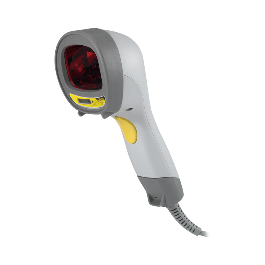
Point-of-Sale Logistic tracking Administration Inventory control Manufacturing Product Overview Buzzer Exit Window LED Indicator Object Detector Function Buzzer button Scan Trigger Pin Hole Cable Connection Z-3060 Service Guide Ver 1.0 Updated 04/20/2011 5 / 14... -
Page 6: Scanner Parts
Magnetic SW board assembly 613-051H05-202 Module jack adaptor assembly 603-030600-161 LED & logo trigger rubber seal 560-030600-951 Top case 560-030600-941 Bottom case 603-030500-121 Trigger rubber seal 613-306001-203 Main board assembly Z-3060 Service Guide Ver 1.0 Updated 04/20/2011 6 / 14... -
Page 7: Take Apart
Tools to Prepare • Philips screwdriver. • Soldering iron Please follow these steps to take apart Z-3060. Remove the bottom cover from the scanner. Remove the front cover of the scanner. Z-3060 Service Guide Ver 1.0 Updated 04/20/2011 7 / 14... - Page 8 Remove the screws pointed in red arrows. Separate the top case from the bottom case and remove the FFC cable as shown in red square. Remove the FFC cable from the scan engine in red square. Z-3060 Service Guide Ver 1.0 Updated 04/20/2011 8 / 14...
- Page 9 Remove the FFC cable shown in red square from the main board. Remove the module jack adapter by lifting it upward. Remove the cables connected to IR board assembly and buzz board assembly in red squares from the main board. Z-3060 Service Guide Ver 1.0 Updated 04/20/2011 9 / 14...
- Page 10 Remove the screws from the LED board as pointed in red arrows. 10. Lift the main board assembly upwards to remove the main board assembly. 11. Remove the trigger rubber seal. Z-3060 Service Guide Ver 1.0 Updated 04/20/2011 10 / 14...
-
Page 11: Buzzer Board Assembly
13. Gently bend the snatch pins on the trigger inwards as illustrated to remove the trigger. Be careful not to break the pins. 14. Remove the screws on the IR board assembly and remove the IR board assembly. Z-3060 Service Guide Ver 1.0 Updated 04/20/2011 11 / 14... -
Page 12: Opto Interrupter Base
15. Remove the opto interrupter base from the IR board. 16. Remove the screws from the magnetic SW board assembly and remove the magnetic SW board assembly. 17. Remove the screws from the LED board on the top case. Z-3060 Service Guide Ver 1.0 Updated 04/20/2011 12 / 14... -
Page 13: Led & Logo Trigger Rubber Seal
18. Remove the LED board and the connector cable. 19. Remove the FFC cable from the buzzer board assembly. 20. Remove the LED & logo trigger rubber seal from the top case. Z-3060 Service Guide Ver 1.0 Updated 04/20/2011 13 / 14... - Page 14 Please note that plastic rods will be damaged and hot glue will be needed to install the new buzzer board. Note: To assemble the scanner, start from the last step and work your way backwards and go over every step slowly. Z-3060 Service Guide Ver 1.0 Updated 04/20/2011 14 / 14...
Need help?
Do you have a question about the Z-3060 and is the answer not in the manual?
Questions and answers