Table of Contents
Advertisement
Quick Links
Advertisement
Table of Contents

Subscribe to Our Youtube Channel
Related Manuals for BYD Battery-Box C130


Summary of Contents for BYD Battery-Box C130
- Page 1 Battery-Box C130 Installation Manual English Version1.1...
-
Page 2: Table Of Contents
CONTENT Information of this Manual ................3 Purpose ........................3 Validity ........................3 Target Group ......................3 Version History......................3 Compatible Inverter Lists ..................3 Acronyms and Abbreviations .................. 3 Safety ........................ 5 Symbols in Document/Product: ................5 Safety Instructions ....................6 2.2.1 Qualified Personnel .................. - Page 3 7.2.5 Modules Number in system ............... 37 Cables between Modules ..................38 7.3.1 Communication Cables between modules..........38 7.3.2 Power cables between Modules............... 39 Insolation Resistance & Puncture Test ..............42 7.4.1 Insolation Resistance test and Puncture Test........... 42 7.4.2 Connect the rest modules .................
- Page 4 BYD shall not be liable for any personal injury, property damage, or any damage caused by non-compliance with this manual from improper use of the product, repairing, openning of the Modules or any other action taken by anyone other than qualified personnel.
- Page 5 CAUTION Improper operating may result in a hazardous situation with minor or moderate injury. NOTICE The information is considered important and need to be paid attention. The information relates to property damage. Copyright© BYD Europe B.V. all rights reserved.
-
Page 6: Information Of This Manual
CAUTION The product must only be operated in connection with a compatible inverter. Manufacture Type REFU REFUStore 88K Acronyms and Abbreviations Abbreviations Full Name Energy Management System Battery Management Unit / Module BMS Copyright© BYD Europe B.V. all rights reserved. - Page 7 Battery Management System Power Distribution Unit (part of BMS) Copyright© BYD Europe B.V. all rights reserved.
-
Page 8: Safety
Place it straight up, without inclination or upside down. Handle with care Keep it dry Recycle Keep the battery modules away from open flame or ignition sources. Beware of electrical voltage. The product operates at high voltages. Beware of flashover voltage Copyright© BYD Europe B.V. all rights reserved. -
Page 9: Safety Instructions
4. Knowledge of and adherence to this document and other documents associated with the product including all safety instructions 5. Training in the installation and commissioning of electrical devices 6. Trained by BYD or organization authorized by BYD. 7. Electrical and installation qualification certificates issued with local permission. 2.2.2 General Instructions To prevent personal injury and property damage. - Page 10 • Store the product out of reach of children and animals • Do not disassemble it, repairing it by unqualified personnel. All services must be done by Copyright© BYD Europe B.V. all rights reserved.
-
Page 11: Handling Modules
Please avoid the following mistakes. • Do not dissemble the module; • Do not charge this product or the module with a charger that is not approved by BYD; • If electrolyte leakage is identified, stop using the product and contact a BYD Authorized Service Partner immediately;... -
Page 12: Response To Emergency Situation
Observe the following precautions when the module has electrolyte leakage. Stop using the battery immediately. Isolate the battery and make sure that it cannot be used any longer. Contact BYD and wait for further handling. The electrolyte is slightly corrosive to the human body. Please avoid contact with it as much as possible. - Page 13 Aim the hose at the base of the flame. Remove the battery from the fire source if possible. If the battery has caught fire, do not attempt to extinguish the fire. Please evacuate people immediately. Copyright© BYD Europe B.V. all rights reserved.
-
Page 14: Location Of Installation
10. Assembling the Storage System must be done in the final desired destination, afterwards moving the battery is no longer possible. Space for installation. The available space reserved for this product should at least meet the requirement shown in Figure below. Copyright© BYD Europe B.V. all rights reserved. - Page 15 Figure 1 Installation Space Copyright© BYD Europe B.V. all rights reserved.
-
Page 16: List Of Needed Tools
Remarks Reference picture Combination tool HW3, PD1, TX25, TX35 and MX8 screwdriver tips and 10 mm and 13mm sockets should be included at least. Electric screwdriver For use in conjunction with screwdriver tips Copyright© BYD Europe B.V. all rights reserved. - Page 17 For checking the battery computer status. CAN box For connecting the product and the commissioning computer CAN box For connecting the CAN box connecting cable Upper computer Software installed in the software commissioning computer. Copyright© BYD Europe B.V. all rights reserved.
-
Page 18: Scope Of Delivery
5. Scope of Delivery Checking the completeness of delivered parts and check if there’s and visible damage. Please contact BYD authorized service partner if any missing or damage founded. 205x Main Parts Designation Qty. Packing condition Reference picture Battery cabinet... -
Page 19: Accessories
Grounding between cabinets wire Terminal Plastic Short Circuit Prevention on Modules strap Cabinets Keys. Open Cabinets Modules Connecter Bolt M6*16 and Hangers Self-tapping Case #2 BMUs Installing. Screws M5*10 Hexagonal nut Cabinets Combination Copyright© BYD Europe B.V. all rights reserved. - Page 20 Bolt: M10*30 Cabinets Combination Bolt: M10*55 Cabinets Combination Case Nut: M10 Cabinets Combination Modules Communication BMUs connection Cords Module Copper Modules Power Connection Connectors Modules Hangers Modules Installing BMUs Modules Controllers Cases Straps Copyright© BYD Europe B.V. all rights reserved.
-
Page 21: Product Overview
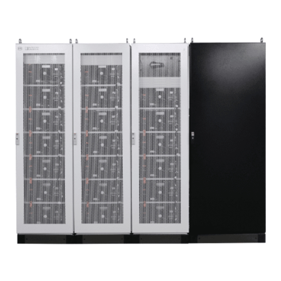
This system consists of 4 cabinets, including 3 battery cabinets and 1 inverter cabinet. The 3 battery cabinets contain 19 battery modules and 1 PDU in total. Battery Cabinet 1 Modules Battery Cabinet 2 Battery Cabinet 3 Inverter Cabinet Copyright© BYD Europe B.V. all rights reserved. -
Page 22: Battery Modules
Fan power cord connector J2 interface J3 interface J1 interface Power Distribution Unit(PDU). The PDU is mainly functioning on distribution and control of the power supply Cover mounting hole Power button and indicator Switch Copyright© BYD Europe B.V. all rights reserved. - Page 23 When the PDU is not powered, the indicator will not illuminate. • 右侧盖板 cover Cable entry hole 1 Cable entry hole 3 Cable entry hole 2 Cable entry hole 4 Copyright© BYD Europe B.V. all rights reserved.
-
Page 24: Installation
Be sure to wear protective equipment such as safety shoes, safety helmets, protective gloves, etc. • Do not stack the cabinet packages with more than 2 layers. The wooden cases will be damaged by the heavy weights. Copyright© BYD Europe B.V. all rights reserved. -
Page 25: Unpacking And Placement Of Cabinets
• 2 person remove the wooden cases Figure 3 • Take out the parts and keep them properly • Take out the cabinet from the wooden cases Figure 4 Figure 2 Figure 3 Figure 4 Copyright© BYD Europe B.V. all rights reserved. -
Page 26: Checking The Accessories And Cabinets
Paint peeling/ Damaged or protruding screws. Figure 5 CAUTION Please contact BYD authorized service partner if any missing or damage founded. 7.1.3 Cabinet Placement • Place the cabinets side by side, by following the labeled number of cabinets. The numbers are showed on the packing cases and inside of cabinets as well --- Figure6. -
Page 27: Remove All Front Doors
• Use diagonal pliers to pull up the upper sheath at the cabinet door connection and pull down the lower sheath to separate each door from cabinet Figure 8 • Keep the doors properly See Figure9. Figure 8 Figure 9 Copyright© BYD Europe B.V. all rights reserved. -
Page 28: Combining The Cabinets
Figure 12, with 9 combiners. • Install all combiner with M6x10 screws. Applying a torque of 6.5 Nm. The process showed below. Figure 12 Figure 11 Figure 10 Figure 11-1 Figure 12-2 Copyright© BYD Europe B.V. all rights reserved. -
Page 29: Grounding Of Cabinets
Grounding of Cabinets. • Grounding the 2 PE cables in the 2# Cabinet. According to Figure 13/14/15 below: • Using original Screws to screw the cables with 10Nm Torques. Figure 13 Figure 15 Figure 14 Copyright© BYD Europe B.V. all rights reserved. -
Page 30: Removing The Pdu
(1) Place the “OUT+” cable, “OUT-“ cable, “RJ45 network” cable and “PDU power cord” to near the installation point in PDU. According to Figure 17. OUT+ RJ45 Network OUT- PDU Power cord Copyright© BYD Europe B.V. all rights reserved. Figure 17 Line Arranging-1... - Page 31 PDU, Figure 18 • Then torque all Power Cable with 18N.m. And draw a mark across the bolt, nut, spring washer, and lug with a marker Figure20. Figure 19 Figure 20 Copyright© BYD Europe B.V. all rights reserved.
- Page 32 Figure 21 Line Arranging-2 • Connecting the “S1P TO BATT+” Cable to Batt+ port in PDU. • Screw and torque with 18Nm and draw a mark with marker. See figure below. Figure 22 Figure 23 Copyright© BYD Europe B.V. all rights reserved.
- Page 33 • Lay the power cable from cabinet2, to the installation points. According to Figure below. Figure 24 LIne Arranging-3 • Lay the 2 power cables from cabinet3, to the installation points. According to Figure below. Copyright© BYD Europe B.V. all rights reserved.
- Page 34 • Connecting the “S1N TO QL1-2” Cable to QLI2 port.. Screw and torque with 18Nm and draw a mark with marker • Connecting the “S2N TO BATT-” Cable to Batt- port. Screw and torque with 18Nm and draw a mark Copyright© BYD Europe B.V. all rights reserved.
- Page 35 (3) Lay the fans power cord from each cabinet to the PDU according to Figure below. Figure 26 Line Arranging-5 • Plug in the 3 fan power Cables to CN5-1/CN5-2/CN5-3 ports in PDU separately. Copyright© BYD Europe B.V. all rights reserved.
-
Page 36: Assembling Modules
NOTICE • The power terminals on modules are protected with covers to prevent short circuit. • Please make sure the covers are always on the modules except testing or connecting the power connectors. Copyright© BYD Europe B.V. all rights reserved. -
Page 37: Unpacking The Modules
• Take out the BMUs and install them to each module using two M5*10 self-tapping screws. Figure34/35 • Plug in the signal collection cord connector into the J3 port of BMU. Figure below. Figure 31 Figure 32 Figure 33 Copyright© BYD Europe B.V. all rights reserved. -
Page 38: Testing Modules Voltages
• Put on the new cover to each terminal after voltage testing. (The original cover is only for protection during shipping). • If any failure or abnormal voltage on module was founded, please contact BYD authorized service partner. • Remove the terminal cover on each modules power terminals. -
Page 39: Installing Modules To Cabinets
• Use a stacker to place modules into cabinet from top to down, and from left to right. Be sure not to knock the cabinet in this process. See 2 Figures beside. Figure 39 Figure 40 Copyright© BYD Europe B.V. all rights reserved. -
Page 40: Fixing Modules
Numbering the modules will help to calibrate and identify the abnormal modules in troubleshooting. It also make it easier to find the right points for power cables connections. Figure 42 Modules Sequence Number Copyright© BYD Europe B.V. all rights reserved. -
Page 41: Cables Between Modules
• Connect port A to the J2 interface shown, connect port B to the J1 interface of the module below, and connect port C to the fan control line interface shown in Figure 43/44. Figure 44 Copyright© BYD Europe B.V. all rights reserved. -
Page 42: Power Cables Between Modules
• The positive and negative poles of each module are marked, Exercise extreme caution to prevent the wrong connecting. • Be aware of avoiding touching the modules positive and negative terminals with the cabinet. Copyright© BYD Europe B.V. all rights reserved. - Page 43 (2)Connecting Modules to Modules. NOTICE Always plug in the Plastic Caps before connecting modules. Plastic Caps were designed for danger prevention. In case of short circuit within module caused by mis-operation. Copyright© BYD Europe B.V. all rights reserved.
- Page 44 Apply a torque of 18 Nm, and draw a red mark. See Figure 50/51 below • Put on the terminal cover and keep the cover on all time. Figure 47 Figure 48 Figure 49 Figure 51 Figure 50 Copyright© BYD Europe B.V. all rights reserved.
-
Page 45: Insolation Resistance & Puncture Test
"Protective each key component grounding Multimeter housing grounding point and the Impedance connection" of IEC point to the housing should be grounding copper bar of cabinet less than 0.1Ω 62109-1 should be satisfied Copyright© BYD Europe B.V. all rights reserved. -
Page 46: Connect The Rest Modules
• Measure the voltage between “BATT+” and “QLI-2”, and between “QL1-3” and “Batt-”. • If the voltages are between 345-437V, the installation could continue. Otherwise, the connection of the power cables should be checked again. Figure 55 Figure 54 Copyright© BYD Europe B.V. all rights reserved. -
Page 47: Close Out Of Battery Installation
Check the PDU power input cable, output cable, PDU power cord, network cable, grounding wire, communication cables between modules and fan wirings are connected properly. According to the 2 Diagrams in showed below Figure56/57. Figure 56 Wiring Diagram-A Figure 57 Wiring Diagram-B Copyright© BYD Europe B.V. all rights reserved. -
Page 48: Check The Torque Has Been Applied On All Points The Power Cable Points
Figure beside.. Figure 58 7.5.4 Install White Baffles. Screw white panels in the cabinets. In Figure beside. White panels are designed for covering the cables in the cabinets • Figure 59 Figure 60 Copyright© BYD Europe B.V. all rights reserved. -
Page 49: Reinstall The 3 White Doors
• Plug in the power cable of PDU indicator on the #2 cabinet door. See Figures beside. Figure 61 Figure 62 7.5.6 Inverter + EMS + Grid Installation/Connection Refer to the instruction or Installation Manual of inverter manufacture. Copyright© BYD Europe B.V. all rights reserved. -
Page 50: Installation Check List
Check the messages via EMS interface. No Warning or Alarming. ◌ ◌ The system can charge and discharge follow the controlled value. Error simulation: Turn off EMS during charging and discharging. The ◌ ◌ system can be shut down automatically. Copyright© BYD Europe B.V. all rights reserved. -
Page 51: Trouble Shooting
The Battery/BMS keep sends status messages to Inverter/EMS. The system will be adjusted or stopped immediately when errors was detected. Always follow the procedures showed in below Table to handle Errors or Event Messages. If errors persist, please contact the BYD Service Line. Event Description... - Page 52 ACTION: Turn off the system Check if the fans communication cables connected correctly. If not, correct or replace the cables. If failure occurs. Replace the BMU. If failure occurs, Please contact service line Copyright© BYD Europe B.V. all rights reserved.
-
Page 53: Shut Down/Turn On The System
1. Turn the Switch to the Vertical Position. Then Press the green-lit on/off switch on the PDU. 2. The Green LED indicator illuminates in green when the battery is on Figure 65 Figure 66 Copyright© BYD Europe B.V. all rights reserved. -
Page 54: Exception Clause For Warranty
If the Product was not operated with a BYD certified inverter, according to BYD Compatible Inverter List (Appendix 1); If the Product has been modified or repaired without the approval of BYD or BYD Partner; If the Product was damaged by force majeure (e.g. natural catastrophes, such as flooding, fires, earthquakes, lightning or other abnormal environmental conditions, war, etc.);... - Page 55 Copyright© BYD Europe B.V. all rights reserved.
-
Page 56: Disposal Of Products And Batteries
For more information, please contact BYD. 13. Service Contact BYD Authorized Service Partner: EFT-Systems GmbH Address: Buchenstr.37 97816 Lohr a. Main Customer Service Mailbox: service@eft-systems.de Telephone: +49 9352 8523999(DE) Website: www.eft-systems.de Copyright© BYD Europe B.V. all rights reserved.
Need help?
Do you have a question about the Battery-Box C130 and is the answer not in the manual?
Questions and answers