Advertisement
OPERATOR MANUAL
IMPORTANT INFORMATION, KEEP FOR OPERATOR
1055 Mendell Davis Drive, Jackson, MS 39272
888-994-7636, fax 888-864-7636
unifiedbrands.net
THIS MANUAL MUST BE RETAINED FOR FUTURE REFERENCE. READ,
UNDERSTAND AND FOLLOW THE INSTRUCTIONS AND WARNINGS
CONTAINED IN THIS MANUAL.
FOR YOUR SAFETY Instructions to be followed in the event user smells
gas. This information shall be obtained by consulting your local gas
supplier. As a minimum, turn off the gas and call your gas company and
your authorized service agent. Evacuate all personnel from the area.
WARNING Improper installation, adjustment, alteration, service or
maintenance can cause property damage, injury or death. Read the
installation, operating and maintenance instructions thoroughly before
installing or servicing this equipment.
NOTIFY CARRIER OF DAMAGE AT ONCE It is the responsibility of the
consignee to inspect the container upon receipt of same and to determine
the possibility of any damage, including concealed damage. Unified
Brands suggests that if you are suspicious of damage to make a notation
on the delivery receipt. It will be the responsibility of the consignee to file
a claim with the carrier. We recommend that you do so at once.
Manufacture Service/Questions 888-994-7636.
EQUIPMENT DESCRIPTION
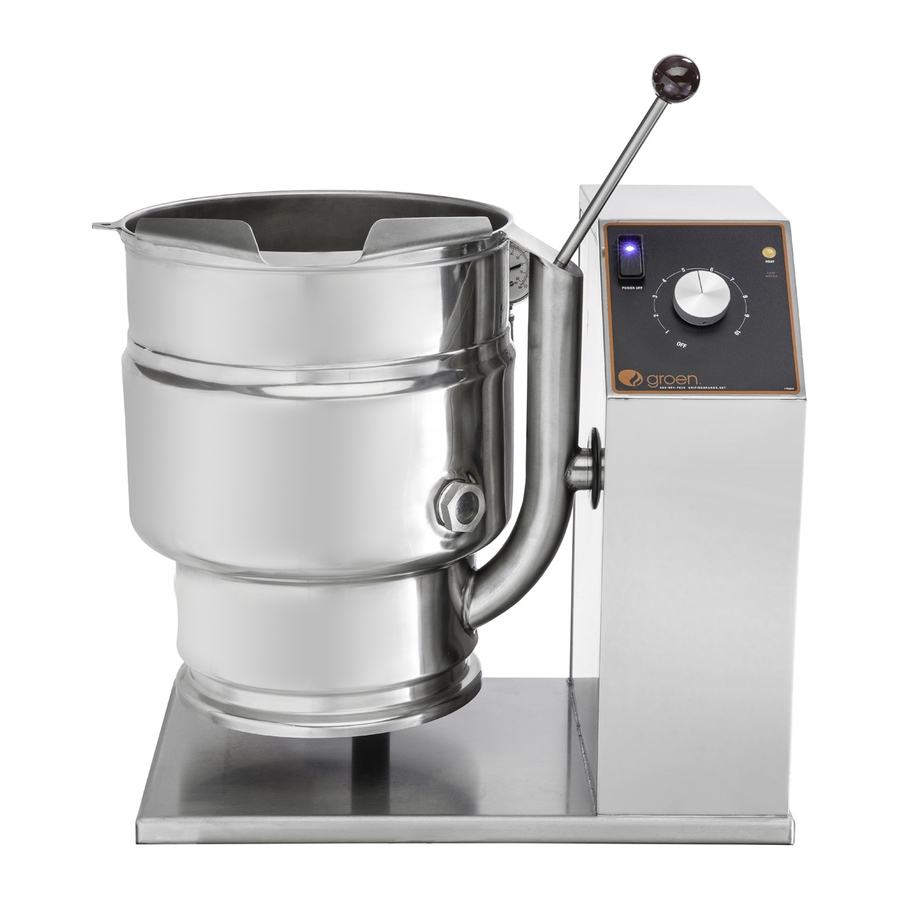
The Groen DH is a floor-mounted, tilting, steam jacketed kettle with a thermostati-
cally or electronically controlled, self-contained, gas-heated steam source and ap-
propriate controls, mounted on a sturdy base. The Model DH is available in 20, 40,
60 or 80 gallon capacities.
The body of the DH Kettle is constructed of stainless steel, welded into one solid
piece. The kettle is furnished with a reinforced rim and a butterfly shaped pouring
lip. It has a steam jacket which is ASME shop inspected and registered with the
national board for working pressures up to 50 PSI. Kettle finish is 180 emery grit
on the inside and bright high buff polish on the outside.
The kettle is tilted with a hand crank to pour out its contents. Stainless steel panels
enclose the controls and the base. Four stainless steel tubular legs support the
unit. Bullet or flanged feet on each of the legs can be adjusted to level the kettle.
Standard DHT units include a two inch tangent draw-off valve.
The self-contained steam source is heated by propane or natural gas. Ignition is
electronic.
The kettle is charged at the factory with chemically pure water which contains rust
inhibitors. The steam source provides kettle temperatures of 150º to approximate-
This manual provides information for:
STEAM JACKETED KETTLE
MODELS DH(T)-20/40/60/80
(C,A,C2T™) DOMESTIC
REFERENCES
CSA INTERNATIONAL
8501 East Pleasant Valley Road
Cleveland, Ohio 44131
NSF INTERNATIONAL
798 N. Dixboro Rd.
P.O. Box 130140
Ann Arbor, Michigan 48113-0140
UNDERWRITERS LABORATORIES, INC.
333 Pfingsten Road
Northbrook, Illinois 60062
KLENZADE SALES CENTER ECOLAB, Inc.
370 Wabasha
St. Paul, Minnesota 55102
ly 295ºF (65 to 150ºC). Unit controls include a thermostat or controller, pressure
gauge, safety valve, pressure limit control, low water cut-off, power switch and
gas regulator valve. The gas supply shuts off automatically when the kettle is tilted.
The unit must be specified for use with natural or propane gas. Service connec-
tions for gas and electricity are required. Standard power supply is 115 Volt. Alter-
nate single-phase voltages (208-240V) are available.
Options available include:
1. Two inch tangent drawoff standard on DHT models
2. Strainers, solid disk, 1/4 or 1/8 inch holes
3. No. 31 lift-off cover
4. No. 51 counterbalanced cover w/actuator*
5. Basket Inserts (Tri-BC)
6. Water fill faucets with swing spout
7. Kettle Brush Kit
Information contained in this document is known to be current and accurate at the time of printing/creation. Unified Brands
recommends referencing our product line websites, unifiedbrands.net, for the most updated product information and
specifications. © 2019 Unified Brands. All Rights Reserved. Unified Brands is a wholly-owned subsidiary of Dover Corporation.
PART NUMBER 174845, REV. E (04/19)
NATIONAL FIRE PROTECTION ASSOCIATION
60 Battery March Park
Quincy, Massachusetts 02269
NFPA/54 -Installation Gas Appliances &
Piping
NFPA/70 - The National Electric Code
ZEP MANUFACTURING COMPANY
1310-T Seaboard Industrial Boulevard
Atlanta, Georgia 30318
AMERICAN NATIONAL STANDARDS INST., INC.
1430 Broadway
New York, New York 10018
Z223.1-1984 - National Fuel Gas Code
Z21.30 - Installation Gas Appliances & Piping
Advertisement
Table of Contents

Subscribe to Our Youtube Channel
Related Manuals for Groen DH-20C


Summary of Contents for Groen DH-20C
- Page 1 Z21.30 - Installation Gas Appliances & Piping EQUIPMENT DESCRIPTION The Groen DH is a floor-mounted, tilting, steam jacketed kettle with a thermostati- ly 295ºF (65 to 150ºC). Unit controls include a thermostat or controller, pressure cally or electronically controlled, self-contained, gas-heated steam source and ap- gauge, safety valve, pressure limit control, low water cut-off, power switch and propriate controls, mounted on a sturdy base.
-
Page 2: Inspection And Unpacking
DO NOT OVER FILL THE KETTLE WHEN COOKING, HOLDING OR CLEANING. KEEP CAUTION: USE OF ANY REPLACEMENT PARTS OTHER THAN THOSE SUPPLIED BY GROEN OR LIQUIDS A MINIMUM OF 2-3” (5-8 cm) BELOW THE KETTLE BODY RIM TO ALLOW THEIR AUTHORIZED SERVICE AGENTS CAN CAUSE OPERATOR INJURY AND DAMAGE CLEARANCE FOR STIRRING, BOILING AND SAFE PRODUCT TRANSFER. -
Page 3: Installation
INSTALLATION 50% of the ultimate strength will be achieved after 20 minutes, 90% after 24 hours and 100% after 72 hours. WARNING: THE UNIT MUST BE INSTALLED BY PERSONNEL WHO ARE QUALIFIED TO 7. Bring electrical service through the entrance at the rear of the support housing WORK WITH GAS, ELECTRICITY AND PLUMBING. -
Page 4: Operation
when the jacket water falls below acceptable levels. When lit, the main 6. Following “To Start Kettle” instructions in the “Operation” section in this manual, begin heating the water at the highest controller setting. The heat indicator light gas valve is disabled and will not function until the jacket water is refilled using the procedure in this manual. - Page 5 READY alarm – The control will sound 3 beeps when the unit has reached Ready alarm – The control will sound 3 beeps when the unit has reached within 20 degrees of set point during pre-heat and when a higher set within 20 degrees of set point during pre-heat and when a higher unit temperature is selected.
- Page 6 OPERATING PROCEDURE 3. If the actual product temperature falls below 142°F. a. An audible alarm along with the display flashing the actual 1. To Start Kettle Heating: product temperature will notify the user that attention is required. a. EVERY DAY make sure that the jacket water level in the middle of the sight glass.
- Page 7 PRECAUTIONS products including eggs, potatoes, vegetables, shell fish, pasta and rice. The nylon mesh liner must be used when cooking product smaller than Before cleaning, shut off the kettle by turning the main power switch to “OFF,” and the mesh size of the basket, which is approximately 1/4” (6 mm). This shut off all electric power to the unit at a remote switch, such as the circuit breaker.
-
Page 8: Maintenance
4. If the valve does not activate, or there is no evidence of discharge, or the CAUTION: INSURE ELECTRICAL POWER IS REMOVED AND THE GAS IS TURNED OFF AT valve leaks, stop using the kettle and contact a qualified Groen service THE SHUTOFF VALVE PRIOR TO PERFORMING ANY MAINTENANCE ON THIS KETTLE. -
Page 9: Replacement Parts
Check the gas supply valves and wait five minutes 1. Obtain water treatment compound and a pH test kit from your Groen Service Agent. before trying again by switching power on. If you cannot establish a pilot flame in four tries, close all valves, turn off the power, and contact an 2. -
Page 10: Troubleshooting
TROUBLESHOOTING This unit is designed to operate smoothly and efficiently if properly maintained. Spark is present Auth Service a. That the pilot valve is securely connected to terminals. X However, the following is a list of checks to make in the event of a problem. but the pilot will Rep Only b. -
Page 11: Parts List
Parts List STAND & HOUSING ASSEMBLY QUANTITY Description Part # WELDMENT, FRAME, STAND 174805 WELDMENT, FRAME, STAND 174802 WELDMENT, CLADDING, STAND 174806 WELDMENT, CLADDING, STAND 174812 WELDMENT, PEDESTAL 175379 WELDMENT, PEDESTAL 175330 WELDMENT, CLADDING, PEDESTAL 175378 WELDMENT, CLADDING, PEDESTAL 175337 PANEL, SIDE, PEDESTAL 175383 PANEL, SIDE, PEDESTAL... - Page 12 Parts List GAS VALVE, PIPING & BOTTOM COMPONENTS OM-DH(T)-20/40/60/80 (C,A,C2T™) Domestic...
- Page 13 Parts List GAS VALVE, PIPING & BOTTOM COMPONENTS QUANTITY QUANTITY Description Part # Description Part # ELBOW, 90 DEG, UNION, 1/2 NPT 005495 TUBE, COPPER, 1/2" OD, SOFT 007334 NIPPLE, 1/2 NPT X CLOSE 008877 ELBOW, 90 DEG, 1/2 NPT, FEMALE 055634 NIPPLE, 1/2 NPT X 3"...
- Page 14 Parts List MODULE BOX Description Part # NUT, LOCK, 1/2, CONDUIT 005487 SCREW, TRUSS HEAD, 8-32 X 005764 3/8" LONG MODULE BOX 123775 GASKET, MODULE BOX 104941 MODULE, IGNITION 085153 NUT, HEX, KEPS, 6-32 071289 ADAPTER, CONDUIT, PLASTIC, 123733 MALE COVER, MODULE BOX 104948 NUT, HEX, KEPS, 8-32...
- Page 15 Parts List BURNER & PILOT/FLAME SENSOR COMPONENTS QUANTITY Description Part # BAFFLE PLATE 123496 BAFFLE PLATE 123497 BAFFLE PLATE 123498 NUT, HEX,SERRATED, 1/4-20 NT1101 PILOT BURNER, NAT GAS 123580 PILOT BURNER, PROPANE 128415 BRACKET, BURNER SUPPORT 117008 BRACKET, BURNER SUPPORT 117009 BRACKET, BURNER SUPPORT 117010...
- Page 16 Parts List FLUE STACK QUANTITY Description Part # 20 Gal 40 Gal 60 Gal 80 Gal FLUE, MAIN BODY 117035 & FRONT SECTION 117036 FLUE, MAIN BODY 117031 & FRONT SECTION 117032 FLUE, MAIN BODY 137874 & FRONT SECTION 137872 FLUE, MAIN BODY 149220 &...
-
Page 17: Control Models
Parts List For Classic & Advanced Control Models ELECTRICAL COMPONENTS Description Part # ASSEMBLY, BOARD, WATER 122192 LEVEL LUG, GROUND, #14 - #6 AWG 129714 SCREW, HEX, SLOTTED HEAD, 069789 8-32 X 3/8" LONG WELDMENT, PANEL, 138123 ELECTRICAL NUT, HEX, KEPS, 10-32 071256 BLOCK, TERMINAL, 2-POLE 003887... - Page 18 Parts List For Cook2Temp™ Control Models ELECTRICAL COMPONENTS Description Part # WELDMENT, ELECTRICAL 138123 MOUNTING DEE & DH-40 TERMINAL BLOCK 2P 003887 P.C. BOARD MOUNTING POST 099901 CONTROL BOARD ASSEMBLY, 122192 WATER LEVEL FUSE 3.0 AMP TYPE 3 AG 077853 FUSE HOLDER TYPE 3 AG 077854 TRANSFORMER, 20VA, 120...
-
Page 19: Front Panel Components
Parts List For Classic Control Models FRONT PANEL COMPONENTS QUANTITY Description Part # 2" ALUMINUM KNOB 175095 POWER SWITCH 176921 INDICATOR LIGHT, AMBER 116384 INDICATOR LIGHT, RED 116383 CLASSIC CONTROLS 174843 HEX NUT 101145 SPACER, LIGHT MOUNT 175221 Bracket, Light Mount 175222 Classic Controls Overlay 175303... - Page 20 Parts List For Cook2Temp™ Control Models FRONT PANEL COMPONENTS QUANTITY Description Part # 2" ALUMINUM KNOB 174829 POWER SWITCH 176921 INDICATOR LIGHT, RED 116383 C2T CONTROLS 176895 HEX NUT 101145 INDICATOR LIGHT, AMBER 116384 SPACER, LIGHT MOUNT 175221 BRACKET, LIGHT MOUNT 175222 OVERLAY, C2T CONTROL 176891...
- Page 21 Parts List TILT MECHANISM COMPONENTS QUANTITY Description Part # BUSHING, SNAP, 3/4" ID 000453 KEY, 3/8" SQUARE X 1-3/8" LONG 001474 SCREW, CAP, SOCKET HEAD, 3/8- 005097 16 X 1-1/2" LONG WASHER, LOCK, SPLIT, 3/8" 005618 NUT, HEX, 1/2-13 005705 WASHER, LOCK, 1/2"...
- Page 22 Parts List WATER LEVEL & SAFETY VALVE COMPONENTS QUANTITY Description Part # ASSEMBLY, WATER FILL 097007 VALVE, SAFETY, 1/2 NPT, 50 PSI 097005 ELBOW, 90 DEG, 1/2 NPT, CHROME 010108 PLATED ASSEMBLY, PLATE & CHAIN 008332 COUPLING, FULL, 1/2 NPT, (NICKEL 149048 PLATED) ELBOW, 90 DEG, STREET, 1/2 NPT...
- Page 23 Parts List REPLACEMENT KETTLE BODY ASSEMBLIES QUANTITY Description Part # REPLACEMENT KETTLE BODY ASSEMBLIES KBA & TRUNNION DH-20 50 PSI 175173 KBA & TRUNNION DHT-20 2" TDO 50 PSI 175174 KBA & TRUNNION DH-40 50 PSI 175179 KBA & TRUNNION DHT-40 2" TDO 50 PSI 175180 KBA &...
-
Page 24: Wiring Diagram
DH(T)-20, -40, -60, -80 For Classic Control Models Wiring Diagram OM-DH(T)-20/40/60/80 (C,A,C2T™) Domestic... - Page 25 DH(T)-20, -40, -60, -80 For Advanced Control Models Wiring Diagram OM-DH(T)-20/40/60/80 (C,A,C2T™) Domestic...
- Page 26 DH(T)-20, -40, -60, -80 For Cook2Temp™ Control Models Wiring Diagram OM-DH(T)-20/40/60/80 (C,A,C2T™) Domestic...
-
Page 27: Service Log
Service Log Model No: Purchased From: Serial No: Location: Date Purchased: Date Installed: Purchase Order No: For Service Call: Date Maintenance Performed Performed By OM-DH(T)-20/40/60/80 (C,A,C2T™) Domestic...
Need help?
Do you have a question about the DH-20C and is the answer not in the manual?
Questions and answers