SMA SUNNY BOY STORAGE 2.5 Operating Manual
Hide thumbs
Also See for SUNNY BOY STORAGE 2.5:
- Quick reference manual (222 pages) ,
- Operating manual (102 pages) ,
- Technical information (6 pages)
Table of Contents
Advertisement
Quick Links
Download this manual
See also:
Quick Reference Manual
Advertisement
Table of Contents

Related Manuals for SMA SUNNY BOY STORAGE 2.5


Summary of Contents for SMA SUNNY BOY STORAGE 2.5
- Page 1 Operating manual SUNNY BOY STORAGE 2.5 ENGLISH SBS25-1VL-10-BE-en-13 | Version 1.3...
- Page 2 SMA Solar Technology AG Legal Provisions The information contained in these documents is the property of SMA Solar Technology AG. No part of this document may be reproduced, stored in a retrieval system, or transmitted, in any form or by any means, be it electronic, mechanical, photographic, magnetic or otherwise, without the prior written permission of SMA Solar Technology AG.
-
Page 3: Table Of Contents
SMA Solar Technology AG Table of Contents Table of Contents Information on this Document..........Validity ........................Target Group......................Content and Structure of this Document ..............Levels of Warning Messages ..................Symbols in the Document ..................Typographies in the Document.................. Designation in the document .................. - Page 4 Table of Contents SMA Solar Technology AG 6.5.1 Assembling the DC Connectors ............. 40 6.5.2 Connecting the power cable of the battery .......... 42 6.5.3 Disassembling the DC Connectors ............43 Commissioning ................. 45 Commissioning Procedure ..................45 Commissioning the Inverter..................46 Selecting a configuration option ................
- Page 5 SMA Solar Technology AG Table of Contents 12 Decommissioning the Inverter..........96 13 Procedure when Replacing a Battery........99 14 Technical Data ................100 15 Spare Parts ................104 16 Contact ..................105 17 EU Declaration of Conformity ..........108 Operating manual SBS25-1VL-10-BE-en-13...
-
Page 6: Information On This Document
1 Information on this Document SMA Solar Technology AG Information on this Document Validity This document is valid for: • SBS2.5-1VL-10 (Sunny Boy Storage 2.5) from firmware version 03.00.00.R Target Group This document is intended for qualified persons and end users. Only qualified persons are allowed to perform the activities marked in this document with a warning symbol and the caption "Qualified person". -
Page 7: Symbols In The Document
SMA Solar Technology AG 1 Information on this Document NOTICE Indicates a situation which, if not avoided, can result in property damage. Symbols in the Document Symbol Explanation Information that is important for a specific topic or goal, but is not safety-rele-... -
Page 8: Additional Information
"Approved batteries and battery communication connection" Technical Information Overview of approved batteries "Application for SMA Grid Guard Code" Form "SMA GRID GUARD 10.0 - Grid management services through Technical Information SMA Inverter" "Efficiency and Derating" Technical Information Efficiency and derating behavior of the SMA inverters "Parameters and Measured Values"... -
Page 9: Safety
All components must remain within their permitted operating ranges and their installation requirements at all times. The product must only be used in countries for which it is approved or released by SMA Solar Technology AG and the grid operator. -
Page 10: Important Safety Instructions
2 Safety SMA Solar Technology AG IMPORTANT SAFETY INSTRUCTIONS SAVE THESE INSTRUCTIONS This section contains safety information that must be observed at all times when working. The product has been designed and tested in accordance with international safety requirements. As with all electrical or electronical devices, there are residual risks despite careful construction. - Page 11 SMA Solar Technology AG 2 Safety WARNING Danger to life due to fire or explosion In rare cases, an explosive gas mixture can be generated inside the product under fault conditions. In this state, switching operations can cause a fire inside the product or explosion.
- Page 12 Sunny Portal or the use of FTP push. High costs for the Internet connection can be the result. • SMA Solar Technology AG recommends using an Internet flat rate. NOTICE Damage to the product due to cleaning agents The use of cleaning agents may cause damage to the product and its components.
- Page 13 SMA Solar Technology AG 2 Safety Change to the names and units of grid parameters to comply with the grid- connection requirements in accordance with Regulation (EU) 2016/631 (valid from April 27, 2019) To comply with the EU grid-connection requirements (valid from April 27, 2019) the names and units of grid parameters were changed.
-
Page 14: Scope Of Delivery
3 Scope of Delivery SMA Solar Technology AG Scope of Delivery Check the scope of delivery for completeness and any externally visible damage. Contact your distributor if the scope of delivery is incomplete or damaged. Figure 1: Components included in the scope of delivery... -
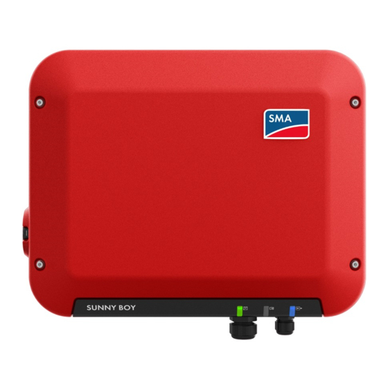
Page 15: Product Overview
SMA Solar Technology AG 4 Product Overview Product Overview Product Description Figure 2: Design of the product Position Designation Connection cap Connection area with cable glands for connection to the utility grid, the battery communication cable and a network cable LEDs The LEDs indicate the operating state of the product. -
Page 16: Symbols On The Product
SMA Solar Technology AG Position Designation Label with QR Code for scanning via the SMA 360° App and easy con- nection to the inverter's user interface via WLAN Type label The type label clearly identifies the product. The type label must remain permanently attached to the product. - Page 17 SMA Solar Technology AG 4 Product Overview Symbol Explanation Observe the documentation Together with the red LED, this symbol indicates an error. Inverter Together with the green LED, this symbol indicates the operating state of the in- verter. Data transmission Together with the blue LED, this symbol indicates the status of the network con- nection.
-
Page 18: Interfaces And Functions
SMA Speedwire The product is equipped with SMA Speedwire as standard. SMA Speedwire is a type of communication based on the Ethernet standard. SMA Speedwire is designed for a data transfer rate of 100 Mbps and enables optimum communication between Speedwire devices within systems. -
Page 19: Led Signals
WLAN connection to SMA 360° app The product has a QR code. By scanning the QR Code attached to the product via the SMA 360° app, access to the product is established via WLAN and the connection to the user interface is made automatically. - Page 20 If an event occurs, a distinct event message and the corresponding event number will be displayed in addition on the product user inter- face or in the communication product (e.g. SMA Data Manager). The blue LED flashes slowly Communication connection is being established for approx.
-
Page 21: System Overview
SMA Solar Technology AG 4 Product Overview System Overview SUNNY PORTAL UTILITY GRID Solar energy Alternating current Communication CUSTOMER SYSTEM SUNNY HOME MANAGER/ SMA ENERGY METER SMA PV SYSTEM SMA STORAGE SYSTEM Operating manual SBS25-1VL-10-BE-en-13... -
Page 22: Circuitry Overview
4 Product Overview SMA Solar Technology AG 4.5.1 Circuitry Overview DISTRIBUTION BOARD SUNNY HOME MANAGER/ SMA ENERGY METER GRID-CONNECTION POINT with energy meter of the grid operator max. 63 A max. max. 16 A 50 A SUNNY BOY UTILITY SUNNY BOY... -
Page 23: Communication Overview
SMA Solar Technology AG 4 Product Overview 4.5.2 Communication Overview SUNNY PORTAL Public Internet Ethernet LAN Radio INTERNET SUNNY BOY ROUTER SUNNY HOME MANAGER/ SMA ENERGY METER SWITCH SUNNY BOY STORAGE BATTERY Figure 4: Design of system communication Operating manual... -
Page 24: Battery Management
4 Product Overview SMA Solar Technology AG "Battery Management" 4.6.1 Battery Use by Systems for Increased Self-Consumption 100 % Figure 5: State of charge ranges of the battery in systems for increased self-consumption without battery backup Range Parameter Battery inverter behavior... -
Page 25: Mounting
SMA Solar Technology AG 5 Mounting Mounting Requirements for Mounting Requirements for the Mounting Location: WARNING Danger to life due to fire or explosion Despite careful construction, electrical devices can cause fires. This can result in death or serious injury. - Page 26 5 Mounting SMA Solar Technology AG Dimensions for mounting: Figure 7: Position of the anchoring points(Dimensions in mm) Recommended clearances: If you maintain the recommended clearances, adequate heat dissipation will be ensured. Thus, you will prevent power reduction due to excessive temperature.
-
Page 27: Mounting The Inverter
SMA Solar Technology AG 5 Mounting Figure 8: Recommended clearances(Dimensions in mm) Mounting the Inverter Additionally required material (not included in the scope of delivery): ☐ Two stainless steel hexagon head wood screws (AF 10, diameter 6 mm), screw length must be suitable for the support surface and the weight of the inverter (fastening bracket thickness: 4 mm) - Page 28 5 Mounting SMA Solar Technology AG 4. Insert screw anchors into the drill holes if the support surface requires them. 5. When screwing the screws in, make sure that there is at least 6 mm left between the screw head and the support surface.
- Page 29 SMA Solar Technology AG 5 Mounting 11. Insert the sealing plug into the DC connector. 12. Insert the DC connectors with sealing plugs into the corresponding DC inputs on the inverter. click ☑ The DC connectors snap into place. 13. Ensure that the DC connectors with sealing plugs are securely in place.
-
Page 30: Electrical Connection
6 Electrical Connection SMA Solar Technology AG Electrical Connection Overview of the Connection Area Figure 9: Connection areas at the bottom of the inverter and cable glands at the connection cap Position Designation DC connectors for connecting the battery power cable Pin connector for connecting the network cable Pin connector for connecting the data cable of the battery. -
Page 31: Ac Connection
• Use a load-break switch or circuit breaker as a load disconnection unit (for information and design examples, see the Technical Information "Circuit Breaker" at www.SMA-Solar.com). ☐ In PV systems with multiple inverters, protect each inverter with a separate circuit breaker. -
Page 32: Connecting The Inverter To The Utility Grid
If you are uncertain about this, contact your grid operator or SMA Solar Technology AG. • Grounding conductor monitoring must be disabled after initial start-up depending on the grid configuration (see Section 8.13, page 66). - Page 33 SMA Solar Technology AG 6 Electrical Connection Procedure: 1. Disconnect the AC circuit breaker and secure it against reconnection. 2. Unscrew the swivel nut from the cable gland for the AC connection at the connector cap. 3. Thread the swivel nut over the AC cable.
-
Page 34: Connecting Additional Grounding
6 Electrical Connection SMA Solar Technology AG 8. Connect L, N and the grounding conductor to the terminal block for the AC connection in accordance with the labeling. When doing so, ensure that the conductors are plugged completely into the terminals up to the insulation. -
Page 35: Connecting The Network Cables
SMA Solar Technology AG 6 Electrical Connection Cable requirements: Use of fine-stranded conductors You can use an inflexible or a flexible, fine-stranded conductor. • When using a fine-stranded conductor, it has to be double crimped by a ring terminal lug. - Page 36 Additionally required material (not included in the scope of delivery): ☐ 1 network cable ☐ Where required: Field-assembly RJ45 connector for the network cable. SMA Solar Technology AG recommends the connector "MFP8 T568 A Cat.6A" from "Telegärtner". Network cable requirements: The cable length and quality affect the quality of the signal.
-
Page 37: Connecting Can Communication Cable
☐ Recommended number of conductor pairs: 4 ☐ Maximum cable length: 10 m ☐ The cable has to be insulated for 600 V. ☐ UV-resistant for outdoor use. SMA Solar Technology AG recommends the cable "UC900 SS23 Cat.7 PE" ☐ Comply with the requirements of the battery manufacturer. - Page 38 6 Electrical Connection SMA Solar Technology AG Assignment of the terminal block: Terminal block Position Assignment Not assigned Enable GND and shielding CAN L CAN H Not assigned Procedure: 1. Thread the swivel nut over the data cable of the battery.
- Page 39 SMA Solar Technology AG 6 Electrical Connection 9. Connect the remaining conductors of the battery communication cable to the 6-pole terminal block. Pay attention to the assignment of the terminal block and communication connection on the battery and/ or automatic transfer switch and make sure that CAN L and CAN H consist of a pair of conductors.
-
Page 40: Dc Connection
6 Electrical Connection SMA Solar Technology AG 16. Screw the swivel nuts onto the cable glands on the connection cap. 17. Connect the other end of the battery communication cable directly to the battery (see the battery manufacturer's manual). DC Connection 6.5.1... - Page 41 SMA Solar Technology AG 6 Electrical Connection Cable requirements: ☐ Cable type: PV1-F, UL-ZKLA, USE2 ☐ External diameter: 5 mm to 8 mm ☐ Conductor cross-section: 2.5 mm² to 6 mm² ☐ Qty single wires: minimum 7 ☐ Nominal voltage: minimum 1000 V ☐ Using bootlace ferrules is not allowed.
-
Page 42: Connecting The Power Cable Of The Battery
6 Electrical Connection SMA Solar Technology AG • Remove the cable and go back to step 2. 5. Push the swivel nut up to the thread and tighten (torque: 2 Nm). 6.5.2 Connecting the power cable of the battery NOTICE Damage to the DC connectors due to the use of contact cleaner of other... -
Page 43: Disassembling The Dc Connectors
SMA Solar Technology AG 6 Electrical Connection 2. Connect the assembled DC connectors to the inverter. click ☑ The DC connectors snap into place. 3. Ensure that all DC connectors are securely in place. 6.5.3 Disassembling the DC Connectors To disassemble the DC connectors (e.g. due to faulty assembly), proceed as follows. - Page 44 6 Electrical Connection SMA Solar Technology AG Procedure: 1. Release and remove the DC connectors. To do so, insert a flat-blade screwdriver or an angled screwdriver (blade width: 3.5 mm) into one of the side slots and pull the DC connectors out. When...
-
Page 45: Commissioning
When the inverter is captured in a communication device, the communication device (e.g. SMA Data Manager) is the unit for configuring the total system. The configuration is transferred to all inverters in the system. The system password assigned via the communication device is also the password for the user interface of the inverter. -
Page 46: Commissioning The Inverter
7 Commissioning SMA Solar Technology AG Commissioning the Inverter WARNING Danger to life due to fire or explosion when batteries are fully discharged A fire may occur due to incorrect charging of fully discharged batteries. This can result in death or serious injury. -
Page 47: Selecting A Configuration Option
SMA Solar Technology AG 7 Commissioning Selecting a configuration option After having assigned the password to the Installer or User, the Configuring the Inverter page opens. Figure 11: Layout of the Configuring the Inverter page Position Designation Description Device information Provides the following information: •... - Page 48 On the Configuring the Inverter page, different configuration options are available to choose from. Select one of the options and proceed for the selected option as described below. SMA Solar Technology AG recommends carrying out the configuration with the installation assistant. This way, you ensure that all relevant parameters are set for optimal inverter operation.
-
Page 49: Starting The Self-Test (For Italy And Dubai)
SMA Solar Technology AG 7 Commissioning 3. Select the desired parameter group. ☑ All available parameters of the parameter group will be displayed. 4. Set the desired parameters. 5. Select [Save all]. ☑ The inverter parameters are set. Starting the Self-Test (for Italy and Dubai) The self-test is only required for inverters that are to be commissioned in Italy or Dubai. -
Page 50: Operation
☐ The respective latest version of one of the following web browsers must be installed: Chrome, Edge, Firefox, Internet Explorer or Safari. ☐ The SMA Grid Guard code of the Installer must be available for the changing of grid-relevant settings after completion of the first ten feed-in hours or installation assistant (see "Application for SMA Grid Guard Code"... - Page 51 ☐ An user account for Sunny Portal must already exist. Procedure: 1. Open the SMA 360° App and login with dem Sunny Portal account details. 2. Select Service > QR-Code Scan. 3. Scan the QR Code on you product via the SMA 360° App.
-
Page 52: Establishing A Connection Via Ethernet In The Local Network
Connection with WLAN network search 1. Search for WLAN networks with your end device. 2. Select the SSID of the inverter SMA[serial number] in the list with the found WLAN networks. 3. Enter the device-specific WLAN password (see WPA2-PSK on the type label of the product or the rear side of the manual included in delivery). -
Page 53: Establishing A Connection Via Wlan In The Local Network
☐ The respective latest version of one of the following web browsers must be installed: Chrome, Edge, Firefox, Internet Explorer or Safari. ☐ The SMA Grid Guard code of the Installer must be available for the changing of grid-relevant settings after completion of the first ten feed-in hours or installation assistant (see "Application for SMA Grid Guard Code"... -
Page 54: Logging In And Out Of The User Interface
☐ The respective latest version of one of the following web browsers must be installed: Chrome, Edge, Firefox, Internet Explorer or Safari. ☐ The SMA Grid Guard code of the Installer must be available for the changing of grid-relevant settings after completion of the first ten feed-in hours or installation assistant (see "Application for SMA Grid Guard Code"... - Page 55 4. Click on Save. 5. In the New password field, enter a password for the Installer user group. Assign a uniform password to all SMA devices to be registered in a system. The installer password is also the system password.
-
Page 56: Start Page Design Of The User Interface
8 Operation SMA Solar Technology AG Start Page Design of the User Interface Figure 12: Design of the user interface's start page (example) SBS25-1VL-10-BE-en-13 Operating manual... -
Page 57: Device Configuration
• Starting the installation assistant • SMA Grid Guard login • Logout Help Provides the following functions: • Displaying information on Open Source licenses used • Link to the website of SMA Solar Technology AG Operating manual SBS25-1VL-10-BE-en-13... - Page 58 8 Operation SMA Solar Technology AG Position Designation Description Status bar Displays the following information: • Inverter serial number • Inverter firmware version • IP address of the inverter within the local network and/or IP address of the inverter during WLAN connection •...
-
Page 59: Starting The Installation Assistant
Requirement: ☐ When configuring after completion of the first ten feed-in hours or after exiting the installation assistant, the SMA Grid Guard code must be available in order to change the grid-relevant parameters (see "Application for SMA Grid Guard Code" at www.SMA-Solar.com). Procedure: 1. -
Page 60: Activate Wps Function
8 Operation SMA Solar Technology AG Activate WPS Function The WPS function can be used for different purposes: • Automatic connection to a network (e.g. via router) • Direct connection between the product and an end device Depending on the intended application of the WPS function, the procedure for activation will vary. -
Page 61: Changing The Password
SMA Solar Technology AG 8 Operation Switching WLAN Off If you would like to switch the WLAN function off completely, you must switch off both the direct connection and the connection in the local network. Procedure: • To switch off the direct connection in the parameter group PV system communication >... -
Page 62: Changing Operating Parameters
3. Call up the menu Device Parameters. 4. Click on [Edit parameters]. 5. Log in using the SMA Grid Guard code to change those parameters designated by a lock (only for installers): • Select the menu User Settings (see Section 8.3, page 56). -
Page 63: Configuring The Country Data Set
SMA Solar Technology AG 8 Operation Accepting the settings Saving the made settings is indicated by an hourglass symbol on the user interface. If the DC voltage is sufficient, the data is transferred directly to the inverter and accepted. If the DC voltage is too low (e.g. -
Page 64: Configuring The Active Power Mode
8 Operation SMA Solar Technology AG 8.10 Configuring the Active Power Mode Starting the installation assistant 1. Open the user interface (see Section 8.1, page 50). 2. Log in as Installer. 3. Start the installation assistant (see Section 8.4, page 59). 4. Select [Save and continue] after each step up until the step Grid management service. -
Page 65: Configuring The Modbus Function
The Modbus interface is deactivated by default and the communication ports 502 set. ® ® ® In order to access SMA invertes with SMA Modbus or SunSpec Modbus , the Modbus interface must be activated. After activating the interface, the communication ports of both IP protocols can be changed. -
Page 66: Activating The Receipt Of Control Signals (Only For Italy)
8 Operation SMA Solar Technology AG 8.12 Activating the Receipt of Control Signals (Only for Italy) In order for PV systems in Italy to receive control commands from the grid operator, set the following parameters. The basic procedure for changing operating parameters is explained in another section (see Section 8.8 "Changing Operating Parameters", page 62). -
Page 67: Setting The Heating Mode For The Battery
SMA Solar Technology AG 8 Operation Removing a detected energy meter from the PV system If only one energy meter is detected by the inverter, this will be added to the PV system automatically. Removal via the menu Device configuration is not possible in this case. To remove the energy meter from the PV system, proceed as follows: •... -
Page 68: Saving The Configuration In A File
Requirements: ☐ Changes to grid-relevant parameters must be approved by the responsible grid operator. ☐ The SMA Grid Guard code must be available (see "Application for SMA Grid Guard Code" at www.SMA-Solar.com). Procedure: 1. Open the user interface (see Section 8.1, page 50). -
Page 69: Updating The Firmware
☐ To update the inverter firmware, the update file with the desired inverter firmware must be available. The update file is, for example, available for download on the product page of the inverter at www.SMA-Solar.com. To download the update file, it is necessary to enter the serial number of the inverter. -
Page 70: Disconnecting The Inverter From Voltage Sources
9 Disconnecting the Inverter from Voltage Sources SMA Solar Technology AG Disconnecting the Inverter from Voltage Sources Prior to performing any work on the inverter, always disconnect it from all voltage sources as described in this section. Always adhere to the prescribed sequence. - Page 71 SMA Solar Technology AG 9 Disconnecting the Inverter from Voltage Sources 7. Remove the plug with the battery communication cable. 8. Release and remove the plug of the network cable. 9. Use a current clamp to ensure that no current is present in the DC conductors.
- Page 72 9 Disconnecting the Inverter from Voltage Sources SMA Solar Technology AG 11. Ensure that no voltage is present at the DC inputs on the inverter using a suitable measuring device. < 3 0 V SBS25-1VL-10-BE-en-13 Operating manual...
-
Page 73: Cleaning The Inverter
SMA Solar Technology AG 10 Cleaning the Inverter 10 Cleaning the Inverter NOTICE Damage due to cleaning agents The use of cleaning agents may cause damage to the product and its components. • Clean the product and all its components only with a cloth moistened with clear water. -
Page 74: Troubleshooting
Installer is the same as the system password in the communication product. Procedure: 1. Request PUK (application form available at www.SMA-Solar.com). 2. Open the user interface (see Section 8.1, page 50). 3. Enter the PUK instead of the password into the field Password. -
Page 75: Event Messages
SMA Solar Technology AG 11 Troubleshooting 11.2 Event Messages Event number Message, cause and corrective measures Grid fault The grid voltage or grid impedance at the connection point of the inverter is too high. The inverter has disconnected from the utility grid. - Page 76 11 Troubleshooting SMA Solar Technology AG Event number Message, cause and corrective measures Grid fault The ten-minute average value of the grid voltage is no longer within the per- missible range. The grid voltage or grid impedance at the connection point is too high.
- Page 77 SMA Solar Technology AG 11 Troubleshooting Event number Message, cause and corrective measures Grid fault The power frequency is not within the permissible range. The inverter has dis- connected from the utility grid. Corrective measures: • If possible, check the power frequency and observe how often fluctuations occur.
- Page 78 11 Troubleshooting SMA Solar Technology AG Event number Message, cause and corrective measures Frequency not permitted > Check parameter The power frequency is not within the permissible range. The inverter has dis- connected from the utility grid. Corrective measures: • If possible, check the power frequency and observe how often fluctuations occur.
- Page 79 SMA Solar Technology AG 11 Troubleshooting Event number Message, cause and corrective measures 1302 Waiting for grid voltage > Installation failure grid connection > Check grid and fuses L or N not connected. Corrective measures: • Ensure that L and N are connected.
- Page 80 11 Troubleshooting SMA Solar Technology AG Event number Message, cause and corrective measures 3501 Insulation failure > Check generator The inverter has detected a ground fault on the DC side. Corrective measures: • Check the battery and DC cabling for ground faults.
- Page 81 SMA Solar Technology AG 11 Troubleshooting Event number Message, cause and corrective measures 6607 6608 Self-diagnosis > Battery overcurrent The battery detected an overcurrent on the DC side. Corrective measures: • Ensure that the battery is correct. • If this message is displayed frequently, contact the Service.
- Page 82 11 Troubleshooting SMA Solar Technology AG Event number Message, cause and corrective measures 7303 Update main CPU failed The cause must be determined by the Service. Corrective measures: • Contact Service. 7324 Wait for update conditions The testing of the update conditions was not successful. The firmware update package is not suitable for this inverter.
- Page 83 SMA Solar Technology AG 11 Troubleshooting Event number Message, cause and corrective measures 7341 Update Bootloader The inverter is performing a bootloader update. 7342 Update Bootloader failed The bootloader update failed. Corrective measures: • Retry update. • If this message is displayed again, contact the Service.
- Page 84 11 Troubleshooting SMA Solar Technology AG Event number Message, cause and corrective measures 7352 Update of WLAN not successful The update of the WLAN module failed. Corrective measures: • Retry update. • If this message is displayed again, contact the Service.
- Page 85 9003 Grid parameter locked Changes to the grid parameters are now blocked. In order to be able to make changes to the grid parameters, from now on you must log in using the SMA Grid Guard code. 9005 Waiting for host computer This error can have the following causes: •...
- Page 86 11 Troubleshooting SMA Solar Technology AG Event number Message, cause and corrective measures 9007 Abort self-test The self-test (Italy only) was terminated. Corrective measures: • Ensure that the AC connection is correct. 9301 New battery detected The inverter has detected a new battery.
- Page 87 9305 Unauthorized battery system The inverter has detected an incorrect battery. Corrective measures: • Only operate batteries with the inverter approved by SMA Solar Technology AG. 9306 Deviation in battery voltage Too high a deviation between the battery and DC voltage of inverter was de- tected.
- Page 88 Battery cell overvoltage fault The battery has detected an overvoltage of at least one battery cell. Corrective measures: • If a service contract with SMA Solar Technology AG exists, contact Service. • If no service contract exists, contact your supplier.
- Page 89 SMA Solar Technology AG 11 Troubleshooting Event number Message, cause and corrective measures 9334 Battery charging test The battery test for charging the battery was started. 9335 Discharge battery test The battery test for discharging the battery was started. 9336...
- Page 90 This message causes a permanent operation in- hibition, which must be reset manually. Corrective measures: • If a service contract with SMA Solar Technology AG exists, contact Service and instruct them to manually charge the battery. • If no service contract exists, contact your supplier.
- Page 91 SMA Solar Technology AG 11 Troubleshooting Event number Message, cause and corrective measures 10110 Time synchronization failed: [x] No time information could be called up from the set NTP server. Corrective measures: • Ensure that the NTP server was configured correctly.
- Page 92 11 Troubleshooting SMA Solar Technology AG Event number Message, cause and corrective measures 10252 [Interface]: communication disrupted There is no valid signal on the network line. Corrective measures: • Ensure that with an Ethernet connection, the network cable and the network connector are not damaged and that the network connectors are correctly plugged.
- Page 93 • If this message is displayed often, improve the WLAN connection by using a WLAN repeater. 10339 Webconnect enabled The inverter can communicate with Sunny Portal without an additional SMA communications product (e.g. Sunny Home Manager). Operating manual SBS25-1VL-10-BE-en-13...
- Page 94 Webconnect disabled The Webconnect function has been switched off. This means that the inverter can not communicate with Sunny Portal without an additional SMA communi- cations product (e.g. Sunny Home Manager). • If the inverter is to communicate with Sunny Portal without an additional SMA communication product, switch the Webconnect function on.
-
Page 95: Problems With Streaming Services
SMA Solar Technology AG 11 Troubleshooting Event number Message, cause and corrective measures 27104 Parameters set successfully The parameter changes were successfully adopted. 27107 Update file OK The update file is suitable for this inverter and its components and is fully avail- able for the next update step. -
Page 96: Decommissioning The Inverter
12 Decommissioning the Inverter SMA Solar Technology AG 12 Decommissioning the Inverter CAUTION Risk of injury due to weight of product Injuries may result if the product is lifted incorrectly or dropped while being transported or mounted. • Transport and lift the product carefully. Take the weight of the product into account. - Page 97 SMA Solar Technology AG 12 Decommissioning the Inverter 6. Tighten the connection cap with the three screws (TX20, torque: 3.5 Nm). 7. Screw the swivel nuts onto the cable glands on the connection cap. 8. If an additional grounding or an equipotential bonding is connected to the inverter, release the hexagon socket cap head screw (TX 25) and...
- Page 98 12 Decommissioning the Inverter SMA Solar Technology AG 10. Remove the inverter from the screws using the metal brackets. 11. If the inverter is to be stored or shipped, pack the inverter. Use the original packaging or packaging that is suitable for the weight and dimensions of the inverter.
-
Page 99: Procedure When Replacing A Battery
SMA Solar Technology AG 13 Procedure when Replacing a Battery 13 Procedure when Replacing a Battery When a connected battery is replaced by a new battery, the battery configuration must be performed. Procedure: 1. Open the user interface (see Section 8.1, page 50). -
Page 100: Technical Data
14 Technical Data SMA Solar Technology AG 14 Technical Data AC connection Rated power at 230 V, 50 Hz 2500 W Maximum apparent AC power at cos φ = 1 2500 VA Rated grid voltage 230 V Nominal AC voltage 220 V / 230 V / 240 V AC voltage range* 180 V to 280 V Nominal AC current at 220 V 11 A... -
Page 101: Protective Devices
Maximum short-circuit current 18 A Battery type* Li-ion Surge category in accordance with IEC 60664-1 * Only use batteries approved by SMA Solar Technology AG (see list of approved batteries at www.SMA-Solar.com) Protective Devices DC reverse polarity protection Not available Input-side disconnection point... -
Page 102: Climatic Conditions
14 Technical Data SMA Solar Technology AG Self-consumption without the load necessary to < 10 W supply the battery Maximum data volume per inverter with Speed- 550 MB/month wire/Webconnect Additional data volume when using the 600 kB/hour Sunny Portal live interface WLAN range in free-field conditions 100 m... -
Page 103: Data Storage Capacity
SMA Solar Technology AG 14 Technical Data Swivel nut of the cable gland for the AC connec- Hand-tight tion. Swivel nut cable gland network and battery Hand-tight communication connection Screws for attaching the connection cap 3.5 Nm ± 0.3 Nm Screw for additional grounding 6 Nm ±... -
Page 104: Spare Parts
15 Spare Parts SMA Solar Technology AG 15 Spare Parts You will find the spare parts for your product in the following overview. If required, these can be ordered from SMA Solar Technology AG or your distributor. Designation Brief description SMA order... -
Page 105: Contact
SMA Solar Technology AG 16 Contact 16 Contact If you have technical problems with our products, please contact the SMA Service Line. The following data is required in order to provide you with the necessary assistance: • Battery inverter: – Device type –... - Page 106 Toll free for Australia: 1800 SMA AUS SMA Online Service Center: (1800 762 287) www.SMA-Service.com International: +61 2 9491 4200 United Arab SMA Middle East LLC India SMA Solar India Pvt. Ltd. Emirates Abu Dhabi Mumbai +971 2234 6177 +91 22 61713888 SMA Online Service Center: www.SMA-Service.com SBS25-1VL-10-BE-en-13 Operating manual...
- Page 107 SMA Solar Technology AG 16 Contact ไทย Service Partner for String inverter: 대한민국 Enerone Technology Co., Ltd Solar Power Engineering Co., Ltd. 4th Fl, Jungbu Bldg, 329, 333/7,8,9 United Tower Build- Yeongdong-daero, Gangnam- ing 4th floor. Soi Sukhumvit 55 (Thonglor 17),...
-
Page 108: Eu Declaration Of Conformity
(L 174/88, June 8, 2011) and 2015/863/EU (L 137/10, March 31, 2015) (RoHS) SMA Solar Technology AG confirms herewith that the products described in this document are in compliance with the fundamental requirements and other relevant provisions of the above- mentioned directives. The entire EU Declaration of Conformity can be found at www.SMA- Solar.com. - Page 110 www.SMA-Solar.com...
Need help?
Do you have a question about the SUNNY BOY STORAGE 2.5 and is the answer not in the manual?
Questions and answers