SMA Sunny Tripower 25000TL Operating Manual
Transformerless pv inverter
Hide thumbs
Also See for Sunny Tripower 25000TL:
- Operating manual (96 pages) ,
- Quick reference manual (49 pages) ,
- Service manual for installers (48 pages)

Related Manuals for SMA Sunny Tripower 25000TL


Summary of Contents for SMA Sunny Tripower 25000TL
- Page 1 Operating Manual SUNNY TRIPOWER 20000TL / 25000TL STP20-25TL-BE-en-10 | 98-112100.01 | Version 1.0 AMERICAN ENGLISH...
- Page 2 The information contained in these documents is property of SMA Solar Technology AG. Any publication, whether in whole or in part, requires prior written approval by SMA Solar Technology AG. Internal reproduction used solely for the purpose of product evaluation or other proper use is allowed and does not require prior approval.
-
Page 3: Table Of Contents
SMA Solar Technology AG Table of Contents Table of Contents Information on this Document ..........Safety..................Intended Use ..................7 Skills of Qualified Persons ..............7 Safety Precautions................8 Scope of Delivery..............Product Description..............10 Sunny Tripower..................10 Interfaces and Functions ..............13 Mounting ................... - Page 4 Table of Contents SMA Solar Technology AG Configuration ................32 Procedure..................... 32 Changing Operating Parameters............32 Setting SMA OptiTrac Global Peak........... 33 Disconnecting the Inverter from Voltage Sources....34 10 Technical Data................36 11 Accessories ................41 12 Contact..................42 13 EC Declaration of Conformity ..........
-
Page 5: Information On This Document
"Qualified person". Tasks that do not require any particular qualification are not marked and can also be performed by end users. Additional Information Links to additional information can be found at www.SMA-Solar.com: Subject Document type and document title Troubleshooting and cleaning, decommissioning Service Manual "Sunny Tripower 20000TL / 25000TL"... - Page 6 1 Information on this Document SMA Solar Technology AG Symbols Symbol Explanation Indicates a hazardous situation which, if not avoided, will result in death or serious injury Indicates a hazardous situation which, if not avoided, can result in death or serious injury...
-
Page 7: Safety
Information "Leading Leakage Currents" at www.SMA-Solar.com). All components must remain within their permitted operating ranges at all times. The product must only be used in countries for which it is approved or released by SMA Solar Technology AG and the grid operator. -
Page 8: Safety Precautions
2 Safety SMA Solar Technology AG 2.3 Safety Precautions This section contains safety precautions that must be observed at all times when working on or with the product. To prevent personal injury and property damage and to ensure long-term operation of the product, read this section carefully and follow all safety precautions at all times. -
Page 9: Scope Of Delivery
SMA Solar Technology AG 3 Scope of Delivery 3 Scope of Delivery Check the scope of delivery for completeness and any externally visible damage. Contact your distributor if the scope of delivery is incomplete or damaged. Figure 1: Components included in the scope of delivery... -
Page 10: Product Description
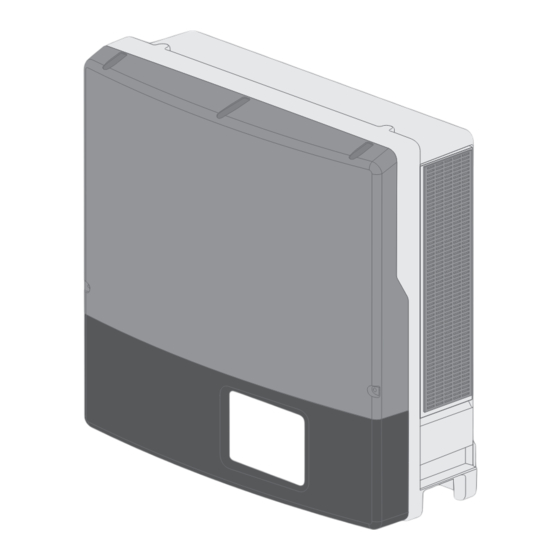
4 Product Description SMA Solar Technology AG 4 Product Description 4.1 Sunny Tripower The Sunny Tripower is a transformerless PV inverter with two MPP trackers which converts the direct current of the PV array to grid-compliant three-phase current and feeds it into the utility grid. - Page 11 SMA Solar Technology AG 4 Product Description Position Designation LEDs The LEDs indicate the operating state of the inverter: • Green LED is glowing: operation • Green LED is flashing: the requirements for the connection to the utility grid have not been met.
- Page 12 4 Product Description SMA Solar Technology AG Symbol Explanation Risk of burns from hot surfaces The product can get hot during operation. Avoid contact during opera- tion. Allow the product to cool down sufficiently before carrying out any work. Wear personal protective equipment such as safety gloves.
-
Page 13: Interfaces And Functions
SMA Solar Technology AG 4 Product Description 4.2 Interfaces and Functions RS485 interface The inverter can communicate via cables with special SMA communication products via the RS485 interface (information on supported SMA products at www.SMA-Solar.com). The RS485 interface can be retrofitted. SMA Speedwire/Webconnect SMA Speedwire/Webconnect is a type of communication based on the Ethernet standard, and... -
Page 14: Mounting
5 Mounting SMA Solar Technology AG 5 Mounting 5.1 Requirements for Mounting Requirements for the mounting location: Danger to life due to fire or explosion Despite careful construction, electrical devices can cause fires. • Do not mount the inverter in areas containing highly flammable materials or gases. - Page 15 SMA Solar Technology AG 5 Mounting Dimensions for mounting: Figure 3: Position of the anchoring points Recommended clearances: Provided that the recommended clearances are observed, adequate heat dissipation will be ensured. Thus, you will prevent power reduction due to excessive temperature.
-
Page 16: Mounting The Inverter
5 Mounting SMA Solar Technology AG ☐ Observe the recommended clearances to walls as well as to other inverters or objects. ☐ If multiple inverters are mounted in areas with high ambient temperatures, increase the clearances between the inverters and ensure sufficient fresh-air supply. - Page 17 SMA Solar Technology AG 5 Mounting ☐ For transporting the inverter with a crane: two eye bolts suitable for the weight of the inverter (size: M10) ☐ To secure the inverter from being lifted off: two screws, washers and screw anchors that are...
- Page 18 5 Mounting SMA Solar Technology AG 2. Align the wall mounting bracket horizontally on the wall and use it to mark the position of the drill holes. Use at least one hole on the right-hand and left-hand side in the wall mounting bracket.
-
Page 19: Electrical Connection
SMA Solar Technology AG 6 Electrical Connection 6 Electrical Connection 6.1 Safety during Electrical Connection Danger to life due to high voltages of the PV array When exposed to sunlight, the PV array generates dangerous DC voltage which is present in the DC conductors and the live components of the inverter. -
Page 20: Overview Of The Connection Area
6 Electrical Connection SMA Solar Technology AG 6.2 Overview of the Connection Area 6.2.1 View from Below Figure 6: Enclosure openings at the bottom of the inverter Position Designation DC load-break switch Enclosure opening M20 with filler plug for the cable of the multifunction relay or SMA Power Control Module... -
Page 21: Interior View
Figure 7: Connection areas in the interior of the inverter Position Designation DC protective cover Pin connector for connecting the multifunction relay or the SMA Power Con- trol Module Pin connector for connecting the communication interface or the data module Connecting terminal plate for the AC cable... - Page 22 ☐ If an external residual-current device is required, install a residual-current device which trips at a residual current of 100 mA or higher (for details on selecting a residual-current device, see the Technical Information "Criteria for Selecting a Residual-Current Device" at www.SMA- Solar.com).
-
Page 23: Connecting The Inverter To The Utility Grid
SMA Solar Technology AG 6 Electrical Connection Connection of additional grounding In some countries, a second grounding is required as a matter of principle (see Section 6.3.3 "Connecting Additional Grounding", page 24). In each case, observe the locally applicable regulations. 6.3.2 Connecting the Inverter to the Utility Grid Requirements: ☐... -
Page 24: Connecting Additional Grounding
6 Electrical Connection SMA Solar Technology AG 6.3.3 Connecting Additional Grounding If connection of additional grounding or equipotential bonding is required at the installation site, you must connect additional grounding to the inverter. This prevents touch current if the grounding conductor at the connecting terminal plate for the AC cable fails. -
Page 25: Connecting The Pv Array
1. Ensure that the circuit breaker is switched off from all three line conductors and that it cannot be reconnected. 2. Check the strings for ground faults (see service manual at www.SMA-Solar.com). 3. Check whether the DC connectors have the correct polarity. -
Page 26: Retrofitting The Surge Arrester Type Ii
6 Electrical Connection SMA Solar Technology AG Damage to the inverter due to moisture ingress The inverter is only properly sealed when all unused DC inputs are closed with DC connectors and sealing plugs. • Do not insert the sealing plugs directly into the DC inputs on the inverter. - Page 27 SMA Solar Technology AG 6 Electrical Connection 2. Release the screws of the DC protective cover using an Allen key (AF 3), lift the DC protective cover upwards from below and remove it. 3. Plug the new surge arresters into the slots provided until they lock into place with the locking tabs.
-
Page 28: Commissioning
7 Commissioning SMA Solar Technology AG 7 Commissioning 7.1 Procedure Procedure Check which country data set the inverter is set to. Supplementary sheet with the default settings or type label If the country data set is not set correctly for your country or Section 7.2, page 28... - Page 29 Country data set in preparation This overview is only an extract at the time of printing. You can find a current, detailed list in the Technical Information "Overview of the Rotary Switch Settings" at www.SMA-Solar.com. Procedure: Danger to life due to high voltages •...
-
Page 30: Commissioning The Inverter
7 Commissioning SMA Solar Technology AG 7.3 Commissioning the Inverter Requirements: ☐ The inverter must be correctly mounted. ☐ The circuit breaker must be correctly rated. ☐ All cables must be correctly connected. ☐ Unused DC inputs must be sealed using the corresponding DC connectors and sealing plugs. - Page 31 The DC input voltage is still too low. • Once the DC input voltage is sufficiently high, feed-in operation begins. ✖ The red LED is glowing? There is probably an error. • Rectify the error (see service manual at www.SMA-Solar.com). Operating Manual STP20-25TL-BE-en-10...
-
Page 32: Configuration
☐ The inverter must be registered in the communication product. ☐ The changes to the grid-relevant operating parameters must be approved by the responsible grid operator. ☐ When changing grid-relevant parameters, the SMA Grid Guard code must be available (see the Certificate "Order Form for the SMA Grid Guard Code" at www.SMA-Solar.com). STP20-25TL-BE-en-10... -
Page 33: Setting Sma Optitrac Global Peak
8 Configuration Procedure: 1. Call up the user interface of the communication product or software and log in as Installer or User. 2. If required, enter the SMA Grid Guard code. 3. Select and set the required parameter. 4. Save settings. 8.3 Setting SMA OptiTrac Global Peak For partially shaded PV modules, set the time interval at which the inverter is to optimize the MPP of the PV system. -
Page 34: Disconnecting The Inverter From Voltage Sources
9 Disconnecting the Inverter from Voltage Sources SMA Solar Technology AG 9 Disconnecting the Inverter from Voltage Sources Prior to performing any work on the inverter, always disconnect it from all voltage sources as described in this section. Always adhere to the prescribed sequence. - Page 35 SMA Solar Technology AG 9 Disconnecting the Inverter from Voltage Sources 7. Release and remove all DC connectors. Insert a slotted screwdriver or an angled screwdriver (blade width 3.5 mm) into one of the slide slots and pull the DC connectors out downwards. Do not pull on the cable.
-
Page 36: Technical Data
10 Technical Data SMA Solar Technology AG 10 Technical Data DC Input STP 20000TL-30 STP 25000TL-30 Maximum DC power at cos φ = 1 20,440 W 25,550 W Maximum input voltage 1,000 V 1,000 V MPP voltage range 320 V to 800 V 390 V to 800 V Rated input voltage 600 V 600 V... - Page 37 SMA Solar Technology AG 10 Technical Data STP 20000TL-30 STP 25000TL-30 Operating range at AC power fre- 44 Hz to 55 Hz 44 Hz to 55 Hz quency 50 Hz Operating range at AC power fre- 54 Hz to 65 Hz 54 Hz to 65 Hz quency 60 Hz Power factor at rated power Displacement power factor, adjustable...
- Page 38 NRS 97-1-2: This standard requires a separate label attached to the AC distribution board which indicates the AC-side disconnection of the inverter in case of a grid failure (for further details, see NRS 97-1-2, Sect. 4.2.7.1 and 4.2.7.2). RD 1699 and RD 661/2007: Contact the SMA Service Line for restrictions in specific regions. STP20-25TL-BE-en-10 Operating Manual...
- Page 39 SMA Solar Technology AG 10 Technical Data Climatic Conditions in Accordance with IEC 60721-3-4, Installation Type C, Class 4K4H Extended temperature range -25°C to +60°C Extended humidity range 0% to 100% Threshold for relative humidity, non-condensing 100% Extended air pressure range 79.5 kPa to 106 kPa Climatic Conditions in Accordance with IEC 60721-3-4, Transport Type E, Class Temperature range -25°C to +70°C...
- Page 40 10 Technical Data SMA Solar Technology AG Event messages for users 250 events Event messages for installers 250 events STP20-25TL-BE-en-10 Operating Manual...
-
Page 41: Accessories
SMA Solar Technology AG 11 Accessories 11 Accessories You will find the accessories for your product in the following overview. If required, these can be ordered from SMA Solar Technology AG or your distributor. Designation Brief description SMA order number... -
Page 42: Contact
12 Contact SMA Solar Technology AG 12 Contact If you have technical problems with our products, contact the SMA Service Line. We need the following information in order to provide you with the necessary assistance: • Inverter device type • Inverter serial number •... - Page 43 Onduleurs : +33 472 09 04 40 Communication : +33 472 09 04 41 Hybrid Energy Solutions Sunny Island : +33 472 09 04 42 Power Plant Solutions Sunny Central : +33 472 09 04 43 India SMA Solar India Pvt. Ltd. +91 22 61713888 Mumbai Italia SMA Italia S.r.l. +39 02 8934-7299 Milano Κύπρος/Kıbrıs Βλέπε Ελλάδα/ Bkz. Ελλάδα (Yunanistan)
- Page 44 SMA Solar Technology AG 대한민국 SMA Technology Korea Co., Ltd. +82 2 508-8599 서울 中国 SMA Beijing Commercial Company +86 10 5670 1350 Ltd. 北京 +971 2 234-6177 SMA Middle East LLC Middle East LLC Other countries International SMA Service Line Toll free worldwide: 00800 SMA SERVICE (+800 762 7378423) Niestetal STP20-25TL-BE-en-10 Operating Manual...
-
Page 45: Ec Declaration Of Conformity
• 2004/108/EC (electromagnetic compatibility, EMC) • 2006/95/EC (low voltage, LVD) SMA Solar Technology AG confirms herewith that the inverters described in this document are in compliance with the fundamental requirements and other relevant provisions of the above mentioned directives. The entire EC Declaration of Conformity can be found at www.SMA- Solar.com. - Page 46 SMA Solar Technology www.SMA-Solar.com...
Need help?
Do you have a question about the Sunny Tripower 25000TL and is the answer not in the manual?
Questions and answers