
Related Manuals for Mitsubishi Electric Melservo-Jet HG-SNS Series


Summary of Contents for Mitsubishi Electric Melservo-Jet HG-SNS Series
- Page 1 Mitsubishi Electric AC Servo System Rotary Servo Motor User's Manual (HG-KNS/HG-SNS) -HG-KNS_ -HG-SNS_...
-
Page 3: Safety Instructions
SAFETY INSTRUCTIONS (Please read the instructions carefully before using the equipment.) To use the equipment correctly, do not attempt to install, operate, maintain, or inspect the equipment until you have read through this manual, installation guide, and appended documents carefully. Do not use the equipment until you have a full knowledge of the equipment, safety information and instructions. -
Page 4: Disposal Of Waste
[Installation/wiring] WARNING ● To prevent an electric shock, turn off the power and wait for 15 minutes or more before starting wiring and/or inspection. ● To prevent an electric shock, ground the rotary servo motor securely. ● To prevent an electric shock, any person who is involved in wiring should be fully competent to do the work. -
Page 5: Table Of Contents
CONTENTS SAFETY INSTRUCTIONS..............1 DISPOSAL OF WASTE . - Page 6 MR-J3ENCBL_M-_-_..............40 MR-J3JCBL03M-_-L .
- Page 7 Fabrication of the encoder cable ............100 REVISIONS.
-
Page 8: Chapter 1 Introduction
INTRODUCTION Model designation The following describes model designation. Not all combinations of the symbols are available. H G - K N S 1 3 B J D Shaft type Symbol Shaft shape None Standard (straight shaft) D cut shaft Keyed shaft Oil seal Symbol Oil seal... -
Page 9: Rating Plate
Rating plate Products applied by Certification Bodies are marked. The mark depends on the Certification Bodies. The production year and month of the rotary servo motor are indicated in the serial number on the rating plate. The year and month of manufacture are indicated by the last two digits of the year and one digit of the month [1 to 9, X (10), Y (11), and Z (12)]. -
Page 10: Environment
Environment Condition Operation Storage Ambient temperature 0 °C to 40 °C (non-freezing) -15 °C to 70 °C (non-freezing) Ambient humidity 10 %RH to 80 %RH (non-condensing) 10 %RH to 90 %RH (non-condensing) Ambience Indoors (no direct sunlight); no corrosive gas, inflammable gas, oil mist or dust Altitude 2000 m or less Vibration resistance... -
Page 11: Parts Identification
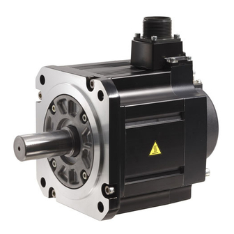
Parts identification HG-KNS series *1 *2 Power cable Encoder cable Power lead (U/V/W) Grounding lead Servo motor shaft Encoder *1 The encoder cable and power supply cable are options. *2 An electromagnetic brake cable is also required for servo motors with an electromagnetic brake. HG-SNS series Power connector Encoder connector... -
Page 12: Electromagnetic Brake
Electromagnetic brake The rotary servo motor with an electromagnetic brake can be used to prevent a drop in vertical lift applications or to ensure double safety at an emergency stop, for example. When operating the rotary servo motor, supply power to the electromagnetic brake to release the brake. - Page 13 Selection of surge absorbers for electromagnetic brake circuit The following shows an example of how to select a varistor as a surge absorber. ■Selection condition Item Condition Electromagnetic brake specification R [Ω]: Resistance L [H]: Inductance Vb [V]: Power supply voltage Desired suppression voltage Vs [V] or less Durable surge application time...
-
Page 14: Rotary Servo Motor Shaft Shapes
Rotary servo motor shaft shapes There are three shaft shape types for the rotary servo motor: keyed shaft (with double round-ended key), keyed shaft (without key), and D cut shaft. To prevent damage to the shaft, do not use the keyed shaft (with double round-ended key), keyed shaft (without key), and D cut shaft for frequent start/stop applications. -
Page 15: Instructions On Storage
Instructions on storage Precautions Note the following when storing the rotary servo motor for an extended period of time (guideline: three or more months). • Always store the linear servo motor indoors, in a clean and dry place. • When storing in a dusty and humid area, take measures such as covering the whole product. •... -
Page 16: Chapter 2 Installation
INSTALLATION Precautions • Install the rotary servo motor on incombustible material. Installing them directly or close to combustibles will lead to smoke or a fire. • Provide an adequate protection to prevent screws and other conductive matter, oil and other combustible matter from entering the rotary servo motor. -
Page 17: Mounting Direction
Mounting direction The mounting direction of the rotary servo motor is shown in the following table. Rotary servo motor series Mounting direction HG-KNS All directions HG-SNS It is recommended that the connector section be set downward for mounting the rotary servo motor in the horizontal direction. Examine the cable clamping method, and give a gentle slack to the connection cable, to prevent excessive load from being applied to the connector and cable connection part. -
Page 18: Load Mounting/Dismounting Precautions
Load mounting/dismounting precautions • When mounting a pulley to the rotary servo motor with a keyed shaft, use the screw hole in the shaft end. To fit the pulley, first insert a double-end bolt into the screw hole of the shaft, put a washer against the end face of the coupling, and insert and tighten a nut to force the pulley in. -
Page 19: Protection From Oil And Water
Protection from oil and water Provide adequate protection to prevent foreign matter, such as oil from entering the rotary servo motor shaft. When installing the rotary servo motor, consider the items in this section. • Do not use the rotary servo motor with its cable soaked in oil or water. Cover Rotary servo... -
Page 20: Rotary Servo Motors With An Oil Seal
Rotary servo motors with an oil seal For rotary servo motors with an oil seal, the oil seal prevents the entry of oil into the rotary servo motor. Make sure to install it in accordance with this section. Even if the oil seal on the rotary servo motor makes noises during operation, it does not indicate a problem with the functions. Pressure and oil level Install the rotary servo motor horizontally, and set the oil level in the gear box to be always lower than the oil seal lip. -
Page 21: Parts With A Service Life
Parts with a service life The service life of the following parts is listed below. If any fault is found in a part, replace it immediately because its service life varies. For parts replacement, please contact your local sales office. Part name Recommended service life Bearings... -
Page 22: Mounting Rotary Servo Motors
2.10 Mounting rotary servo motors Be sure to use the rotary servo motor within the specified environment, and mount the rotary servo motor on a machine having the equivalent heat dissipation effect as the following aluminum flange. The temperature of the rotary servo motor increases differently depending on its mounting environment, operating conditions, and other factors. -
Page 23: Chapter 3 Connectors Used For Rotary Servo Motor Wiring
CONNECTORS USED FOR ROTARY SERVO MOTOR WIRING Precautions • The indicated IP rating is the connector's protection against ingress of dust and water when the connector is connected to a rotary servo motor. If the IP rating of the connector and rotary servo motor varies, the overall IP rating depends on the lowest IP rating of all components. -
Page 24: Wiring Connectors (Connector Configurations A/B/C)
Wiring connectors (connector configurations A/B/ Connector Feature Connector Crimping tool Rotary servo motor configuration encoder connector A (for encoder) IP65 Connector: 2174053-1 For ground clip: 1596970-1 1674339-1 (TE Connectivity) For receptacle contact: 1596847-1 (TE Connectivity) (TE Connectivity) *1 The connector to be mated. Connector Feature Connector... -
Page 25: Wiring Connectors (Connector Configurations D/E/F/G)
Wiring connectors (connector configurations D/E/ F/G) Angle plug Angle plug (one-touch connection type) (screw type) Straight plug Straight plug (one-touch connection type) (screw type) Connector Feature Plug (DDK) Rotary configuration servo Type Plug Socket contact Contact shape Cable OD motor [mm] encoder (reference) - Page 26 Plug Cable clamp Cable Plug Cable clamp Cable Connector Feature Plug (DDK) Cable clamp (DDK) Rotary servo motor configuration power connector Type Model Cable OD [mm] Model (reference) E (for power IP67 Straight CE05-6A18-10SD-D-BSS 8.5 to 11 CE3057-10A-2-D MS3102A18-10P supply) EN compliant Applicable wire size: AWG 14 to 12 10.5 to 14.1...
- Page 27 Angle plug Angle plug (one-touch connection type) (screw type) Straight plug Straight plug (one-touch connection type) (screw type) Connector Feature Plug (DDK) Rotary servo configuration motor Type Plug Socket Contact shape Cable OD electromagnetic contact [mm] brake (reference) connector F (for IP67 Straight CMV1-SP2S-S...
- Page 28 Plug Cable clamp Cable Plug Cable clamp Cable Connector Feature Plug (DDK) Cable clamp (DDK) Rotary servo motor configuration power connector Type Model Cable OD [mm] Model (reference) G (for power IP67 Straight CE05-6A22-22SD-D-BSS 9.5 to 13 CE3057-12A-2-D MS3102A22-22P supply) EN compliant Applicable wire size: AWG 10 to 8 12.5 to 16...
-
Page 29: Chapter 4 Connection Of Servo Amplifier And Rotary Servo Motor
CONNECTION OF SERVO AMPLIFIER AND ROTARY SERVO MOTOR Precautions • Insulate the conductive parts of the terminals. • To prevent unexpected operation of the rotary servo motor, wire the equipment correctly and securely. • Make sure to connect the cables and connectors by using the fixing screws and the locking mechanism. Otherwise, the cables and connectors may be disconnected during operation. -
Page 30: Precautions For Wiring
Precautions for wiring For grounding, connect the grounding lead wire from the servo motor to the protective earth (PE) terminal of the servo amplifier, and then connect the wire from the servo amplifier to the ground via the protective earth of the cabinet. Do not connect the wire directly to the protective earth (PE) terminal of the cabinet. -
Page 31: Wiring
Wiring To wire to the servo amplifier, use connectors packed with the servo amplifier or optional connectors. For connectors, refer to "Wiring CNP1" in the following manual. MR-JET User's Manual (Hardware) HG-KNS series Servo motor power supply cable wiring diagrams ■When cable length is 10 m or less 10 m or shorter MR-PWS1CBL_M-A1-L... - Page 32 Electromagnetic brake cable wiring diagrams ■When cable length is 10 m or less 10 m or shorter MR-BKS1CBL_M-A1-L MR-BKS1CBL_M-A2-L Rotary MR-BKS1CBL_M-A1-H 24 V DC servo motor power supply MR-BKS1CBL_M-A2-H for electromagnetic (Electromagnetic brake brake interlock) (Malfunction) AWG 20 AWG 20 *1 Connect a surge absorber as close to the servo motor as possible.
-
Page 33: Hg-Sns Series
HG-SNS series Refer to the following for the wires used for wiring. Page 34 Selection example of wires Wiring diagram 50 m or shorter Rotary Servo amplifier servo motor 24 V DC power supply (Electromagnetic for electromagnetic brake interlock) (Malfunction) brake *1 *4 *1 The electromagnetic brake terminals (B1 and B2) have no polarity. - Page 34 Rotary servo motor terminal section The rotary servo motor terminal section is shown in the following table. Refer to the following for the details of the connectors. Page 32 Details of the rotary servo motor connectors The connector fitting the rotary servo motor is prepared as options. Refer to the following for details of the options.
- Page 35 ■Connector B Power connector MS3102A18-10P Terminal No. Signal (PE) ■Connector C Power connector MS3102A22-22P Terminal No. Signal (PE) ■Connector D Electromagnetic brake connector CMV1-R2P Terminal No. Signal *1 Supply electromagnetic brake power (24 V DC). There is no polarity. 4 CONNECTION OF SERVO AMPLIFIER AND ROTARY SERVO MOTOR 4.2 Wiring...
-
Page 36: Selection Example Of Wires
Selection example of wires Wires indicated in this section are separated wires. When using a cable for power line (U/V/W) between the servo amplifier and rotary servo motor, use a 600 V grade EP rubber insulated chloroprene sheath cab-tire cable (2PNCT). For cable selection, refer to the following. Page 93 Selection example of rotary servo motor power cable To comply with the UL/CSA standard, use the wires shown in the following for wiring. -
Page 37: Chapter 5 Wiring Option
WIRING OPTION Precautions • Use specified options. Otherwise, it may cause a malfunction or fire. • MR-J3SCNS(A) and MR-ENCNS2(A) connector sets are packed with a plug and contacts. As using contacts for other plugs may damage the connector, use the enclosed contacts. •... - Page 38 HG-SNS series Servo amplifier (26) (31) (34) (35) (24) (25) CNP1 (29) (30) (32) (33) (27) (28) Rotary servo motor Power Electromagnetic Encoder connector brake connector connector *1 The battery (available in the near future) is required when constructing an absolute position detection system. 5 WIRING OPTION 5.1 Cable/connector sets...
-
Page 39: Cable And Connector List
Cable and connector list Product Model Description Remark name Servo motor MR-PWS1CBL_M-A1-L IP65 power cable Cable length: 2/5/10 m Load-side lead Power connector Servo motor MR-PWS1CBL_M-A1-H IP65 power cable Cable length: 2/5/10 m Load-side lead Long bending life Page 54 Servo motor power cable Servo motor MR-PWS1CBL_M-A2-L IP65... - Page 40 Product Model Description Remark name (13) Encoder cable MR-J3ENCBL_M-A1-L IP65 Cable length: 2/5/10 m Load-side lead Encoder connector (14) Encoder cable MR-J3ENCBL_M-A1-H IP65 Cable length: 2/5/10 m Load-side lead Long bending life Page 40 MR-J3ENCBL_M-_-_ (15) Encoder cable MR-J3ENCBL_M-A2-L IP65 Cable length: 2/5/10 m Lead in opposite Encoder connector...
- Page 41 Product Model Description Remark name (27) Power MR-PWCNS4 IP67 connector set EN compliant HG-SNS52 HG-SNS102 HG-SNS152 Plug: CE05-6A18-10SD-D-BSS Cable clamp: CE3057-10A-1-D (DDK) Applicable cable Applicable wire size: 2 mm to 3.5 mm (AWG 14 to 12) Cable OD: 10.5 mm to 14.1 mm (28) Power MR-PWCNS5...
-
Page 42: Encoder Cable/Connector Sets
Encoder cable/connector sets Encoder cables are not subject to European Low Voltage Directive (50 V AC to 1000 V AC and 75 V DC to 1500 V DC). MR-J3ENCBL_M-_-_ These cables are motor cables for the HG-KNS series rotary servo motors. Model The following describes what each block of a model name indicates. - Page 43 CN2-side connector (1) The following shows the view from the wiring side. Do not connect anything to the pins shown with a diagonal line. Securely connect the external conductor of the shielded cable to the ground plate and fix it to the connector shell. Page 60 Shield procedure of CN2 side connectors Receptacle: 36210-0100PL Shell kit: 36310-3200-008...
-
Page 44: Mr-J3Jcbl03M-_-L
MR-J3JCBL03M-_-L These cables are motor cables for the HG-KNS series rotary servo motors. The servo amplifier and the rotary servo motor cannot be connected by these cables alone. The servo motor-side encoder cable (MR-EKCBL_M-_) is required. Model The following describes what each block of a model name indicates. Not all combinations of the symbols are available. M R - A 1 - Bending life... - Page 45 Junction connector (1) The following shows the view from the wiring side. Do not connect anything to the pins shown with a diagonal line. Housing: 1-172169-9 Contact: 1473226-1 Cable clamp: 316454-1 Crimping tool: 91529-1 (TE Connectivity) CONT Encoder-side connector (2) The following shows the view from the wiring side.
-
Page 46: Mr-J3Jscbl03M-_-L
MR-J3JSCBL03M-_-L These cables are motor cables for the HG-KNS series rotary servo motors. The servo amplifier and the rotary servo motor cannot be connected by these cables alone. The servo motor-side encoder cable (MR-J3ENSCBL_M-_) is required. Model The following describes what each block of a model name indicates. Not all combinations of the symbols are available. M R - A 1 - Bending life... - Page 47 Junction connector (1) The following shows the view from the wiring side. Do not connect anything to the pins shown with a diagonal line. Receptacle: CM10-CR10P-M (DDK) Applicable wire size: AWG 20 or lower Encoder-side connector (2) The following shows the view from the wiring side. Do not connect anything to the pins shown with a diagonal line. Connector: 2174053-1 Crimping tool for ground clip: 1596970-1 Crimping tool for receptacle contact: 1596847-1...
-
Page 48: Mr-Ekcbl_M
MR-EKCBL_M-_ The following encoder cables are of four-wire type. • MR-EKCBL30M-L • MR-EKCBL30M-H • MR-EKCBL40M-H • MR-EKCBL50M-H When using any of these encoder cables, refer to the user's manual (parameters) and select "four-wire type" for the corresponding servo parameter. The servo amplifier and the rotary servo motor cannot be connected by these cables alone. Motor cables for rotary servo motors (MR-J3JCBL03M-_-L) are needed. - Page 49 CN2-side connector (1) The following shows the view from the wiring side. Do not connect anything to the pins shown with a diagonal line. Securely connect the external conductor of the shielded cable to the ground plate and fix it to the connector shell. Page 60 Shield procedure of CN2 side connectors Receptacle: 36210-0100PL Shell kit: 36310-3200-008...
- Page 50 Internal wiring diagram When fabricating the cable, use the wiring diagram corresponding to the length indicated below. Cable bending life Applicable wiring diagram Less than 30 m 30 m to 50 m Standard MR-EKCBL20M-L MR-EKCBL30M-L Long bending life MR-EKCBL20M-H MR-EKCBL30M-H MR-EKCBL40M-H MR-EKCBL50M-H ■MR-EKCBL20M-L...
- Page 51 ■MR-EKCBL20M-H CN2-side Junction connector connector Plate *1 Always make connection for use in an absolute position detection system. Wiring is not necessary for use in an incremental system. ■MR-EKCBL30M-H/MR-EKCBL40M-H/MR-EKCBL50M-H CN2-side Junction connector connector CONT Plate *1 Always make connection for use in an absolute position detection system. Wiring is not necessary for use in an incremental system. When fabricating an encoder cable Prepare the following parts, and fabricate the cable in accordance with the following.
-
Page 52: Mr-J3Enscbl_M
MR-J3ENSCBL_M-_ These cables are encoder cables for the HG-KNS/HG-SNS series rotary servo motors. Model The following describes what each block of a model name indicates. Not all combinations of the symbols are available. M R - J 3 E N S C B L 2 Bending life Symbol Bending life... - Page 53 CN2-side connector (1) The following shows the view from the wiring side. Do not connect anything to the pins shown with a diagonal line. Securely connect the external conductor of the shielded cable to the ground plate and fix it to the connector shell. Page 60 Shield procedure of CN2 side connectors Receptacle: 36210-0100PL Shell kit: 36310-3200-008...
- Page 54 Cable internal wiring diagram ■MR-J3ENSCBL2M-L/MR-J3ENSCBL5M-L/MR-J3ENSCBL10M-L/MR-J3ENSCBL2M-H/MR- J3ENSCBL5M-H/MR-J3ENSCBL10M-H CN2-side Encoder-side connector connector Plate *1 Always make connection for use in an absolute position detection system. Wiring is not necessary for use in an incremental system. ■MR-J3ENSCBL20M-L/MR-J3ENSCBL30M-L CN2-side Encoder-side connector connector Plate *1 Always make connection for use in an absolute position detection system. Wiring is not necessary for use in an incremental system. ■MR-J3ENSCBL20M-H/MR-J3ENSCBL30M-H/MR-J3ENSCBL40M-H/MR-J3ENSCBL50M-H CN2-side Encoder-side...
- Page 55 When fabricating an encoder cable Prepare the following parts, and fabricate the cable in accordance with the following diagram. Page 52 Cable internal wiring diagram Refer to the following for the specifications of the cable to use. Page 58 Wires for option cables Parts Description (Connector set)
-
Page 56: Servo Motor Power Cable
Servo motor power cable These cables are servo motor power cables for the HG-KNS series servo motors. Refer to the following for details regarding wiring. Page 35 HG-KNS series Model The following describes what each block of a model name indicates. Not all combinations of the symbols are available. M R - P W S 1 A 1 -... - Page 57 Connection of servo amplifier and rotary servo motor Servo amplifier MR-PWS1CBL_M-A1-L MR-PWS1CBL_M-A1-H MR-PWS2CBL03M-A1-L CNP1 Rotary Servo amplifier servo motor power connector MR-PWS1CBL_M-A2-L MR-PWS1CBL_M-A2-H MR-PWS2CBL03M-A2-L Rotary servo motor Cable model Servo motor power-side connector (1) MR-PWS1CBL_M-A1-L Connector: KN4FT04SJ1-R Hood/socket insulator MR-PWS1CBL_M-A2-L Bushing/ground nut MR-PWS1CBL_M-A1-H Contact: ST-TMH-S-C1B-100-(A534G)
-
Page 58: Electromagnetic Brake Cable
Electromagnetic brake cable These cables are electromagnetic brake cables for the HG-KNS series servo motors. Refer to the following for details regarding wiring. Page 35 HG-KNS series Model The following describes what each block of a model name indicates. Not all combinations of the symbols are available. M R - B K S 1 A 1 -... - Page 59 Connecting the electromagnetic brake power supply and the rotary servo motor MR-BKS1CBL_M-A1-L MR-BKS1CBL_M-A1-H MR-BKS2CBL03M-A1-L Rotary 24 V DC power servo motor supply for electromagnetic brake MR-BKS1CBL_M-A2-L MR-BKS1CBL_M-A2-H MR-BKS2CBL03M-A2-L Rotary servo motor Cable model Connector for electromagnetic brake (1) MR-BKS1CBL_M-A1-L Connector: JN4FT02SJ1-R Hood/socket insulator MR-BKS1CBL_M-A2-L 1 B1...
-
Page 60: Wires For Option Cables
Wires for option cables List of applicable recommended wires Type Model Length Core Number Characteristics of one core Cable Recommended size wire model Structure Conductor Insulator cores [mm] (manufacturer) [Wires/ resistance outer [Ω/mm] diameter (d) [mm] Encoder cable MR-J3ENCBL_M-A1-L 2 to 10 AWG 22 6 (3 7/0.26... - Page 61 Type Model Length Core Number Characteristics of one core Cable Recommended size wire model Structure Conductor Insulator cores [mm] (manufacturer) [Wires/ resistance outer [Ω/mm] diameter (d) [mm] Servo motor MR-PWS1CBL_M-A1-L 2 to 10 AWG 18 34/0.18 21.8 or less 1.71 6.2 ±...
-
Page 62: Shield Procedure Of Cn2 Side Connectors
Shield procedure of CN2 side connectors For the CN2 side connector, securely connect the shielded external conductor of the cable to the ground plate and fix it to the connector shell. Cable Ground plate Screw 5 WIRING OPTION 5.6 Shield procedure of CN2 side connectors... -
Page 63: Chapter 6 Hg-Kns Series
HG-KNS SERIES This chapter provides information on the rotary servo motor specifications and characteristics. If using the HG-KNS series rotary servo motor, read chapters 1 to 5 and the Safety Instructions at the front of this manual in addition to this chapter. Standard specifications Standard specifications list Series... -
Page 64: Torque Characteristics
Rotary servo motor Vibration 1000 0 1000 2000 3000 4000 5000 6000 Speed [r/min] V10 indicates that the amplitude of a single rotary servo motor is 10 μm or less. The following figure shows the rotary servo motor mounting position for measurement and the measuring position. Rotary servo motor Measuring position Bottom... -
Page 65: Combinations Of Servo Amplifiers And Rotary Servo Motors
Combinations of servo amplifiers and rotary servo motors Rotary servo motor Servo amplifier HG-KNS13 MR-JET-10G_ HG-KNS23 MR-JET-20G_ HG-KNS43 MR-JET-40G_ HG-KNS73 MR-JET-70G_ 6 HG-KNS SERIES 6.2 Combinations of servo amplifiers and rotary servo motors... -
Page 66: Characteristics Of Electromagnetic Brake
Characteristics of electromagnetic brake Before operating the servo motor, confirm that the electromagnetic brake operates properly. The operation time of the electromagnetic brake varies depending on the power supply circuit being used. Check the operation delay time with an actual machine. The characteristics of the electromagnetic brake provided for the rotary servo motor with an electromagnetic brake are shown below. -
Page 67: Rotary Servo Motors With Special Shafts
Rotary servo motors with special shafts There are two shaft shape types for the rotary servo motor: keyed shaft (with double round-ended key) and D cut shaft. Rotary servo motor Shaft shape Keyed shaft (with double round-ended key) D cut shaft ... -
Page 68: Rotary Servo Motors With An Oil Seal
Rotary servo motors with an oil seal The oil seal prevents the entry of oil into the rotary servo motor. Install the rotary servo motor horizontally, and set the oil level in the gear box to be always lower than the oil seal lip. Gear Shaft Rotary servo motor Height above... -
Page 69: Mounting Connectors
Mounting connectors If the connector is not fixed securely, it may come off or may not produce a splash-proof effect during operation. To achieve the IP rating IP65, pay attention to the following points when installing the connectors. • When screwing the connector, hold the connector still and gradually tighten the screws in a crisscross pattern. Connector for power, connector for encoder Tightening order Connector for electromagnetic brake... -
Page 70: Dimensions
Dimensions • When running the cables to the load side, take care to avoid interference with the machine. • Not all parts are created the exact same size or assembled in precisely the same manner. Therefore, the actual dimensions of rotary servo motors may be a maximum of approximately 3 mm larger than those in the drawings. In addition, the described dimensions and dimensional tolerances are the values at 20 °C. - Page 71 ■HG-KNS23J □60 4-φ5.8 Oil seal Encoder connector 13.7 10.9 11.7 13.9 28.4 21.7 18.6 27.8 45.6 Power connector POWER POWER No. Signal (PE) 21.7 18.6 Opposite-load side Connector pin assignment Servo motor flange direction → BC69225* [Unit: mm] ■HG-KNS43J 109.7 □60 4-φ5.8 Oil seal...
- Page 72 ■HG-KNS73J 122.2 □80 4-φ6.6 Oil seal Encoder connector 13.7 11.5 10.7 11.7 27.4 21.7 18.6 27.8 77.6 Power connector POWER POWER No. Signal (PE) 21.7 18.6 Opposite-load side Connector pin assignment Servo motor flange direction → BC69227* [Unit: mm] Without oil seal ■HG-KNS13 82.4 □40...
- Page 73 ■HG-KNS23 76.6 □60 4-φ5.8 Encoder connector 13.710 10.9 11.7 13.9 28.4 11.8 21.7 18.6 27.8 36.4 Power connector POWER POWER No. Signal (PE) 21.7 18.6 Opposite-load side Connector pin assignment Servo motor flange direction → BC69217* [Unit: mm] ■HG-KNS43 98.3 □60 4-φ5.8 Encoder connector...
- Page 74 ■HG-KNS73 □80 4-φ6.6 Encoder connector 13.7 11.5 10.7 11.7 27.4 11.8 21.7 18.6 27.8 69.6 Power connector POWER POWER No. Signal (PE) 21.7 18.6 Opposite-load side Connector pin assignment Servo motor flange direction → BC69219* [Unit: mm] 6 HG-KNS SERIES 6.7 Dimensions...
-
Page 75: With An Electromagnetic Brake
With an electromagnetic brake With oil seal ■HG-KNS13BJ 129.6 □40 □43 2-φ4.5 21.5 Oil seal Encoder connector 13.7 10.9 11.7 13.9 27.4 11.7 21.7 18.6 27.5 57.4 18.4 47.8 Brake connector Power connector POWER POWER No. Signal (PE) 21.7 18.4 Opposite-load side BRAKE BRAKE... - Page 76 ■HG-KNS43BJ 146.5 □60 4-φ5.8 Oil seal Encoder connector 13.7 10.9 11.7 13.9 28.4 21.7 18.6 27.8 67.3 Brake connector Power connector POWER POWER No. Signal (PE) BRAKE BRAKE No. Signal 21.7 18.5 Connector pin assignment Opposite-load side BC69238* Servo motor flange direction → [Unit: mm] ■HG-KNS73BJ 162.5...
- Page 77 Without oil seal ■HG-KNS13B □40 20.5 20.7 2-φ4.5 21.5 Encoder connector 13.7 10.9 11.7 13.9 6.4 27.4 11.7 21.7 18.6 27.5 58.8 18.4 39.8 Brake connector Power connector POWER POWER No. Signal (PE) 21.7 18.4 Opposite-load side BRAKE BRAKE No. Signal Connector pin assignment BC69220* Servo motor flange direction →...
- Page 78 ■HG-KNS43B 135.1 □60 4-φ5.8 Encoder connector 13.7 10.9 11.7 13.9 28.4 11.8 21.7 18.6 27.8 57.8 58.1 Brake connector Power connector POWER POWER No. Signal (PE) BRAKE BRAKE No. Signal 21.7 18.5 Connector pin assignment Opposite-load side BC69222* Servo motor flange direction → [Unit: mm] ■HG-KNS73B 152.3...
-
Page 79: Chapter 7 Hg-Sns Series
HG-SNS SERIES This chapter provides information on the rotary servo motor specifications and characteristics. If using the HG-SNS series rotary servo motor, read chapters 1 to 5 and the Safety Instructions at the front of this manual in addition to this chapter. Standard specifications Standard specifications list Series... - Page 80 Rotary servo motor Vibration 1000 1000 2000 3000 Speed [r/min] *5 V10 indicates that the amplitude of a single rotary servo motor is 10 μm or less. The following figure shows the rotary servo motor mounting position for measurement and the measuring position. Rotary servo motor Measuring position Bottom...
-
Page 81: Torque Characteristics
Torque characteristics • For the system where the unbalanced torque occurs, such as a vertical axis, the unbalanced torque of the machine should be kept at 70 % or lower of the rated torque. • When the power supply voltage drops, the torque decreases. When the power supply input of the servo amplifier is 3-phase 200 V AC or 1-phase 230 V AC, the torque characteristic is indicated by the heavy line. -
Page 82: Combinations Of Servo Amplifiers And Rotary Servo Motors
Combinations of servo amplifiers and rotary servo motors Rotary servo motor Servo amplifier HG-SNS52 MR-JET-70G_ HG-SNS102 MR-JET-100G_ HG-SNS152 MR-JET-200G_ HG-SNS202 HG-SNS302 MR-JET-300G_ 7 HG-SNS SERIES 7.2 Combinations of servo amplifiers and rotary servo motors... -
Page 83: Characteristics Of Electromagnetic Brake
Characteristics of electromagnetic brake Before operating the servo motor, confirm that the electromagnetic brake operates properly. The operation time of the electromagnetic brake varies, depending on the power supply circuit being used. Check the operation delay time with an actual machine. The characteristics of the electromagnetic brake provided for the rotary servo motor with an electromagnetic brake are shown below. -
Page 84: Rotary Servo Motors With Special Shafts
Rotary servo motors with special shafts The shaft shape for the rotary servo motor is keyed shaft (without key)-type. Rotary servo motor Shaft shape Keyed shaft (without key) HG-SNS_K Keyed shaft (without key) Section A-A [Unit: mm] Rotary servo motor Variable dimensions HG-SNS52_K +0.2... -
Page 85: Rotary Servo Motors With An Oil Seal
Rotary servo motors with an oil seal The oil seal prevents the entry of oil into the rotary servo motor. Install the rotary servo motor horizontally, and set the oil level in the gear box to be always lower than the oil seal lip. Gear Shaft Rotary servo motor Height above... -
Page 86: Dimensions
Dimensions • Not all parts are created the exact same size or assembled in precisely the same manner. Therefore, the actual dimensions of rotary servo motors may be a maximum of approximately 3 mm larger than those in the drawings. In addition, the described dimensions and dimensional tolerances are the values at 20 °C. - Page 87 HG-SNS102/HG-SNS102J 132.5 □130 38.2 4-φ9 Oil seal Encoder connector CMV1-R10P 20.9 13.5 Power connector MS3102A18-10P 71.8 (PE) Power connector BC69253* Servo motor flange direction → [Unit: mm] *1 For the servo motor with an oil seal HG-SNS152/HG-SNS152J 146.5 □130 38.2 4-φ9 Oil seal Encoder connector...
- Page 88 HG-SNS202/HG-SNS202J 138.5 □176 38.5 4-φ13.5 Oil seal Encoder connector CMV1-R10P 24.8 Power connector MS3102A22-22P 74.8 (PE) Power connector BC69255* Servo motor flange direction → [Unit: mm] *1 For the servo motor with an oil seal HG-SNS302/HG-SNS302J 162.5 □176 38.5 4-φ13.5 "1 "1 Oil seal...
-
Page 89: With An Electromagnetic Brake
With an electromagnetic brake HG-SNS52B/HG-SNS52BJ □130 43.5 4-φ9 Oil seal Encoder connector CMV1-R10P Electromagnetic brake connector CMV1-R2P 20.9 13.5 57.8 Power connector MS3102A18-10P (PE) Position mark Electromagnetic Power connector brake connector BC69257* Servo motor flange direction → [Unit: mm] *1 For the servo motor with an oil seal HG-SNS102B/HG-SNS102BJ □130 43.5... - Page 90 HG-SNS152B/HG-SNS152BJ □130 43.5 4-φ9 Oil seal Encoder connector CMV1-R10P Electromagnetic brake connector CMV1-R2P 20.9 13.5 85.8 Power connector MS3102A18-10P (PE) Position mark Electromagnetic Power connector brake connector BC69259* Servo motor flange direction → [Unit: mm] *1 For the servo motor with an oil seal HG-SNS202B/HG-SNS202BJ □176 45.5...
- Page 91 HG-SNS302B/HG-SNS302BJ □176 45.5 4-φ13.5 "1 "1 Oil seal "2 "2 Encoder connector CMV1-R10P 66.5 Electromagnetic brake connector CMV1-R2P 24.8 Power connector 98.8 MS3102A22-22P (PE) Position mark Electromagnetic Power connector brake connector Servo motor flange direction → BC69261* [Unit: mm] *1 Screw hole for eyebolt (M8) *2 For the servo motor with an oil seal 7 HG-SNS SERIES 7.6 Dimensions...
-
Page 92: Chapter 8 Compliance With Each Region
COMPLIANCE WITH EACH REGION Compliance with CE marking CE marking The CE marking is mandatory and must be affixed to specific products placed on the European Union. When a product conforms to the requirements, the CE marking must be affixed to the product. CE marking also incorporates the machines and equipments that are for sale with the servo motors in the European Union area. -
Page 93: Compliance With Ul/Csa Standard
Compliance with UL/CSA standard Use the UL/CSA standard-compliant model of rotary servo motor. For the latest information of compliance, contact your local sales office. Unless otherwise specified, the handling, performance, specifications, etc., of the UL/CSA compliant products are the same as those of the standard models. Flange size The rotary servo motor is compliant with the UL/CSA standard when it is mounted on the flanges made of aluminum whose sizes are indicated in the following table. -
Page 94: Chapter 9 Appendix
APPENDIX Rotary servo motor ID codes Rotary servo motor series ID Rotary servo motor type ID Rotary servo motor encoder ID Rotary servo motor 0117 FF13 0044 HG-KNS13 FF23 HG-KNS23 FF43 HG-KNS43 FF73 HG-KNS73 012B FF52 HG-SNS52 F102 HG-SNS102 F152 HG-SNS152 F202 HG-SNS202... -
Page 95: Selection Example Of Rotary Servo Motor Power Cable
Selection example of rotary servo motor power cable Selection conditions of wire size are as follows. Wiring length: 30 m or less As some cables do not fit in the optional or recommended cable clamp, select cable clamps applicable to the cable diameters. -
Page 96: Connector Dimensions
Connector dimensions The connector dimensions for wiring the rotary servo motor are shown below. TE Connectivity ■2174053-1 24.6 φ13.6 [Unit: mm] *1 The recommended screw tightening torque is 0.1 N•m. Crimping tool: 1596970-1 (for ground clip) 1596847-1 (for receptacle contact) ■JN4FT02SJ1-R 26.6 12.3... - Page 97 ■KN4FT04SJ1-R (29) 16 ± 0.3 11.7 ± 0.2 12.2 ± 0.3 Main key [Unit: mm] *1 The recommended screw tightening torque is 0.2 N•m. Crimping tool: CT170-14-TMH5B 9 APPENDIX 9.3 Connector dimensions...
- Page 98 ■CMV1-SP10S-M_/CMV1-SP2S-_ Refer to the following for details of the crimping tool. Page 23 Wiring connectors (connector configurations D/E/F/G) (50) For CMV1-SP10S-M_ For CMV1-SP2S-_ [Unit: mm] ■CMV1-AP10S-M_/CMV1-AP2S-_ Refer to the following for details of the crimping tool. Page 23 Wiring connectors (connector configurations D/E/F/G) (32) For CMV1-AP10S-M_ For CMV1-AP2S-_...
- Page 99 ■CMV1S-AP10S-M_/CMV1S-AP2S-_ Refer to the following for details of the crimping tool. Page 23 Wiring connectors (connector configurations D/E/F/G) (32) For CMV1S-AP10S-M_ For CMV1S-AP2S-_ [Unit: mm] ■CE05-6A_-_SD-D-BSS D or shorter 7.85 or longer [Unit: mm] Model CE05-6A18-10SD-D-BSS 1 1/8-18UNEF-2B 34.13 32.1 1-20UNEF-2A CE05-6A22-22SD-D-BSS 1 3/8-18UNEF-2B...
- Page 100 ■CE3057-_A-_-D A ± 0.7 Effective thread length C V-thread φE (Cable clamp ID) (Movable range on one side) φF (Bushing ID) [Unit: mm] Model Shell size Bushing Cable OD CE3057-10A-1-D 23.8 30.1 10.3 41.3 15.9 14.1 31.7 1-20UNEF-2B CE3420-10-1 10.5 to 14.1 CE3057-10A-2-D 11.0 CE3420-10-2...
- Page 101 ■D/MS3057-_A Effective thread A ± 0.7 φE (Bushing ID) length C φD (Cable clamp ID) F (Movable range) [Unit: mm] Model Shell size Bushing D/MS3057-10A 23.8 30.1 10.3 15.9 14.3 31.7 1-20UNEF AN3420-10 D/MS3057-12A 23.8 35.0 10.3 19.0 15.9 37.3 1 3/16-18UNEF-2A AN3420-12 ■CE05-6A32-17SD-D...
-
Page 102: Fabrication Of The Encoder Cable
Fabrication of the encoder cable It is recommended to use options indicated in the following section for the encoder cable. Page 35 WIRING OPTION When fabricating an encoder cable, use the recommended products described in the following sections. Page 21 CONNECTORS USED FOR ROTARY SERVO MOTOR WIRING Page 27 CONNECTION OF SERVO AMPLIFIER AND ROTARY SERVO MOTOR Page 35 WIRING OPTION When fabricating encoder cables, note the descriptions in this section, in order to ensure the reliability of communication. - Page 103 MEMO 9 APPENDIX 9.4 Fabrication of the encoder cable...
-
Page 104: Revisions
First edition This manual confers no industrial property rights or any rights of any other kind, nor does it confer any patent licenses. Mitsubishi Electric Corporation cannot be held responsible for any problems involving industrial property rights which may occur as a result of using the contents noted in this manual. -
Page 105: Warranty
WARRANTY Warranty 1. Warranty period and coverage We will repair any failure or defect hereinafter referred to as "failure" in our FA equipment hereinafter referred to as the "Product" arisen during warranty period at no charge due to causes for which we are responsible through the distributor from which you purchased the Product or our service provider. -
Page 106: Trademarks
TRADEMARKS MELSERVO is a trademark or registered trademark of Mitsubishi Electric Corporation in Japan and/or other countries. All other product names and company names are trademarks or registered trademarks of their respective companies. IB(NA)-0300488ENG-A... - Page 108 IB(NA)-0300488ENG-A(1911)MEE MODEL: MODEL CODE: HEAD OFFICE : TOKYO BUILDING, 2-7-3 MARUNOUCHI, CHIYODA-KU, TOKYO 100-8310, JAPAN NAGOYA WORKS : 1-14 , YADA-MINAMI 5-CHOME , HIGASHI-KU, NAGOYA , JAPAN When exported from Japan, this manual does not require application to the Ministry of Economy, Trade and Industry for service transaction permission. Specifications are subject to change without notice.
Need help?
Do you have a question about the Melservo-Jet HG-SNS Series and is the answer not in the manual?
Questions and answers