Table of Contents
Advertisement
MMA 6120-TCD/MP3
ZONINGAMPLIFIER
CD/MP3
PREV
NEXT
PAUSE
PLAY
REPEAT FOLDER
PRG
FM/AMTUNER
FUNCTION
BAND
DOWN
UP
MEMORY
M1
M2
M3
MMA 6120-TCD/MP3
MMA 6240-TCD/MP3
- 9
- 6
-12
EJECT
-15
VOLUME
STOP
Z O N E 1
PWR
0
10
VOLUME
0
10
SCAN
ME
M4
M5
SHIFT
ZONING AMPLIFIER
- 9
- 6
- 9
- 6
- 3
- 3
- 3
-12
-12
0dB
-15
0dB
-15
0dB
-15
Z O N E 2
Z O N E 3
M I C 3
M I C 4
AUX
0
10
0
10
M I C 1
M I C 2
0
10
0
10
User manual
- 9
- 6
- 9
- 6
- 9
- 6
- 3
- 3
-12
-12
-12
0dB
-15
0dB
-15
Z O N E 4
Z O N E 5
Z O N E 6
BASS
TUNER CD/MP3
0
OFF
MASTERVOLUME
-10
+10
LINESELECT
LINE
TREBLE
0
0
0
10
-10
+10
0dB
-6
-10
- 3
-18
0dB
-25
POWER
10
Advertisement
Table of Contents

Related Manuals for Fbt Audio Contractor MMA 6120-TCD/MP3


Summary of Contents for Fbt Audio Contractor MMA 6120-TCD/MP3
-
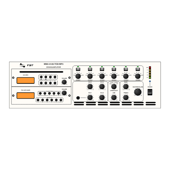
Page 1: User Manual
ZONING AMPLIFIER MMA 6120-TCD/MP3 MMA 6240-TCD/MP3 MMA 6120-TCD/MP3 ZONINGAMPLIFIER CD/MP3 PREV NEXT PAUSE EJECT VOLUME PLAY STOP Z O N E 1 Z O N E 2 Z O N E 3 Z O N E 4 Z O N E 5 Z O N E 6 REPEAT FOLDER M I C 3... - Page 2 All information included in this operating manual have been scrupulously controlled; however FBT is not responsible for eventual mistakes. FBTElettronicaSpAhastherighttoamendproductsandspecificationswithoutnotice.
- Page 3 FRONT MMA6240-TCD/MP3 ZONINGAMPLIFIER C D / M P 3 PREV NEXT PAUSE EJECT VOLUME PLAY STOP Z O N E 1 Z O N E 2 Z O N E 3 Z O N E 4 Z O N E 5 Z O N E 6 REPEAT FOLDER M I C 3...
-
Page 4: Table Of Contents
CONTENT Preperation Device Functions - Rear Side - Unpacking 5 115V and 230V Mains Connection 15 Safety Instructions 5 24V Battery Connection 15 General Information 5 Ω 100V/8 Speaker Output Cooling 6 Aerial Connection 17 Desktop Mounting 6 LINE OUT 18 LINE IN AUX 19 Priorities 20 Input sensitivity MIC 1 20... -
Page 5: Unpacking
PREPARATION Unpacking - Unpacking Please note the unpacking instructions - Safety Instructions - General Information Safety Instructions - Cooling Please note the safety instructions before - Desktop Mounting connecting the MT-AMP 06 General Information Instructions for the installation Cooling Please note the ventilation - cooling guidelines Desktop Mounting Please note the positioning of the Mixer Amplifier... - Page 6 PREPARATION General Information Unpacking !DO NOT run microphone cables near mains, Please verify if the following parts were delivered: data, telephone or 100V line cables. !DO NOT run 100V line cables near data, ! line cord telephone or other low voltage cables. !DO NOT exceed 90% of the amplifiers output power when using 100V line (speech only).
-
Page 7: Cooling
PREPARATION Cooling The mixer amplifer pulls fresh air through the small holes in the bottom sheet and pushes the exhaust air through the long holes in the top sheet. Please make sure that the internal space of the rack system is cooling and you have a room maximum temperature of 40°C.. -
Page 8: Special Characteristics
SPECIAL CHARACTERISTICS - Paging Microphone Functions Paging Microphone Functions - Output Function ! 4 Microphone inputs with different Priorities ! 1 AUX - Common Function Output Function - Inputs - Outputs ! 6 Zones switchable and adjustable ! Music muting ! Pre-Amplifier Output Common Function ! 115V and 230V Mains Connection... -
Page 9: Led - Display
DEVICE FUNCTIONS Front Side - LED - Display LED - Display - On/Off - switch Display for the activation - Zoning ON/OFF - Switch - VU-Display Setting - up the Mixer-Amplifier Microphone Input MIC 1 Zoning - Microphone Controller Choosing the Output Zone - LINE - Controller VU-Display LINE - Select:... - Page 10 DEVICE FUNCTIONS Front Side LED - Display LED - Display The LED-Display shows the operational readiness of the Mixer Amplifier. Zoning ON/OFF - Switch With this switch you turn on the apparat. In addition to the normal 100V line output you can Position I = apparat is on select 6 Zones by using the push buttons on the Position 0 = apparat is off...
- Page 11 DEVICE FUNCTIONS Front Side VU - Display The VU-Display shows the saturation degree of the Mixer Amplifier. The green LED’s indicates the level which can be run continously without any interferences. The red LED is iluminated at the full saturation degree only. This level is not appropriate for enduring operation.
- Page 12 DEVICE FUNCTIONS Front Side Microphone Controller Using this controller you can set the volume of the microphones. Microphone Controller LINE - Select: switch AUX, Tuner, CD-MP3, OFF LINE - Controller You can activate connected signal soureces with the LINE - Select switch. LINE - Controller switch The volume of the connected Signal Sources can be adjusted by the LINE - Controller switch.
-
Page 13: Controller Bass And Treble
DEVICE FUNCTIONS Front Side Bass and Treble Controller Controller By using this controller you can adjust the Bass and Treble reproduction of deep and high frequencies. The bass control lifts or lowers frequencies near to 100Hz at 10dB. The treble-control has the same effect on frequencies near to 10.000Hz. -
Page 14: Tuner Operation
DEVICE FUNCTIONS Front Side CD Operation 1. Select CD mode with LINE select switch. 2. Press Power key on CD-Player 6 7 8 9 3. Load disc into player and Play starts automatically 4. Press Pause key and the play will be suspended. -
Page 15: 115V And 230V Mains Connection
DEVICE FUNCTIONS Rear Side - 115V and 230V Mains Connection 115V and 230V Mains Connection - 24V Battery Connection Selector to adapt the mains connection 24V Battery Supply Ω - 100V/8 Speaker Output Connection to UPS - Aerial Connection 100V/8ohm Speaker Output - LINE OUT Terminal for 100V/8ohm - speakers Aerial Connection... - Page 16 DEVICE FUNCTIONS Rear Side 115V and 230V Mains Connection Mains Selector The amplifier is factory set at 230 V(AC) mains voltage. The Mains Selector is at the rearside of the Mixer Amplifier. You can set the switch to 115V if neccessary by pushing the slide switch from right to left.
- Page 17 DEVICE FUNCTIONS Rear Side 100V Speaker Output 8ohm Speaker Output The amplifier provides six different 100V speaker This output allows connection of standard low Zones. Additionally you can connect the speakers impedance speakers. The minimum load with one 25V or 70V Zone. impedance must be 8ohm When two or more loudspeakers are connected, ensure that they are ! The 100V - Output reproduces all signals...
- Page 18 DEVICE FUNCTIONS Rear Side Aerial Connection The MT-AMP 06 provides the possibility to connect two antennas (FM and AM) at the rearside of the gear. The connection can be done by the AM- clamps oder the FM jacket. Antenna connection...
- Page 19 DEVICE FUNCTIONS Rear Side LINE OUT These standard RCA phono sockets provide a mixed output suitable for connection of an amplifier. Please note: The connection of an power amplifier is providing you an additional zone. This zone is not adjustable (Music/Speech, Speech only). The power for the 6 zones will remain at 240W.
- Page 20 DEVICE FUNCTIONS Rear Side LINE IN (CD/AUX) The equipment provides an auxiliary input which may be used for connecting of other signal sources such as a CD- or Cassette player. A slide switch is located on the front panel for selection of Aux and CD.
- Page 21 DEVICE FUNCTIONS Rear Side Microphone input with XLR-Jack XLR-Input Mic 1 input is either a balanced standard 1/4” stereo jack on front panel or XLR on the rear panel 1: SCREEN (with selectable phantom power). Mic1 input has 2: HOT VOX priority which will be override Mic2-4 and AUX (LINE) input signals but not the Telephone 3: COLD...
-
Page 22: Chime
DEVICE FUNCTIONS Rear Side Telephone Input This input is for emergency announcements / signals and is not effected by the Master Control. The input level can be set by rotary control on the rear panel. The TEL input has the highest priority and will The TEL input has the highest priority override all other inputs. -
Page 23: Monitor Output
DEVICE FUNCTIONS Rear Side MONITOR OUTPUT If the speaker zone is not in the same room as the amplifier you can supervise the output with the connectors on the terminal strip marked as MONITOR OUTPUT. There are several options. 1.Connection of an ear phone Ω... -
Page 24: Top View Of All Functions
DEVICE FUNCTIONS Rear Side Top view of all functions 100V Line PagingMIC Microphone FM Antenna AMAntenna MONITOR Z O N E 6 ZONE 5 ZONE 4 Telephone- system Amplifier ZONE 3 Z O N E 2 Z O N E 1 TUNER... -
Page 25: Further Information
FURTHER INFORMATION - Technical Specifications Technical Specifications - Block Plugging Diagramm Containing all technical specifications - Index Block Plugging Diagram Circuit construction Index Content in alphabetical order... -
Page 27: Block Plugging Diagram
FURTHER INFORMATION Block Plugging Diagram...
Need help?
Do you have a question about the Audio Contractor MMA 6120-TCD/MP3 and is the answer not in the manual?
Questions and answers