Table of Contents
Advertisement
Quick Links
Advertisement
Table of Contents

Related Manuals for Fbt symbol 12000


Summary of Contents for Fbt symbol 12000
- Page 1 Symbol Symbol 12000 18000 Professional Stereo Amplifiers ENGLISH FBT elettronica S.p.A. - Via Paolo Soprani 1 - Zona Ind.le Squartabue - 62019 RECANATI (MC) - ITALY TEL. 071/750591 r.a. - FAX 071/7505920 - http://www.fbt.it - E-mail : info@fbt.it...
-
Page 2: Table Of Contents
Here are the “no-compromise” power amplifiers ! The new Symbol Power Amplifier series features two models based on a project design targeted to obtain the most appropriate technical solutions to each and every need of signal amplification. The Symbol 12000 and the Symbol 16000 grant stereo power output of respectively 1500 W and 2400 W per channel (into 2 ohm). -
Page 3: Precautions
- Do not connect audio inputs to electrical power sources of any type. - If a fault occurs, consult your nearest FBT service centre or a specialized audio equipment repair service. Do not attempt to repair the amplifier yourself. -
Page 4: Front Panel / Rear Panel
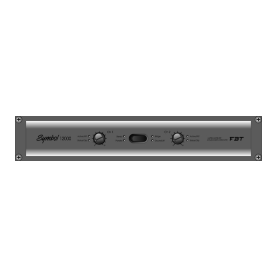
FRONT PANEL Ch 1 Ch 2 Symbol Active/PRT Stereo Bridge Active/PRT 18000 ULTRA LINEAR CASCODE CIRCUITS Status/Clip Parallel Ground Lift Status/Clip REAR PANEL LINK LINK Symbol 18000 GND LIFT STEREO PARALLEL BRIDGE (CH1) Ch 2 Ch 1 INPUTS 2 OHM MIN. 4 OHM MIN. -
Page 5: Controls 3
CONTROLS DESCRIPTION 3] Status / Clip Amplifier operating status indicator LED: - green indicates that the amplifier is functioning normally Ch 1 - red indicates that the signal has reached the saturation threshold (clipping level) in the amplification stage (in this case reduce the volume by means of the Ch1 / Ch2 (1) controls). -
Page 6: Controls 3
Mono output with Speakon connector. To connect a loudspeaker to both amplifier circuits in BRIDGE mode. The loudspeaker (or array of loudspeakers connected in series/parallel) must have minimum impedance of 4 ohms and power handling of at least 3000W (Symbol 12000) or 4800W (Symbol 18000). 4 OHM MIN. -
Page 7: Installation
INSTALLATION SYMBOL amplifiers are designed for rack mounting (two standard 19" rack spaces) and are supplied with four fixing holes on the front panel flanges. The rear panel features two pins (A) designed to engage in the rack. The amplifier is equipped with two cooling fans operating at variable speed in relation to the temperature. For efficient operation of the amplifier, ensure that the rear panel air expulsion grilles are unobstructed. -
Page 8: Operating Modes
OPERATING MODES STEREO When the input signal is stereo, use STEREO mode, selectable on the rear panel. The left hand and right hand channel signals MIXER must be connected to the amplifier INPUT1 and INPUT2 respectively. The signal will be amplified in stereo and delivered to the OUT1 and OUT2 outputs;... -
Page 9: Cables And Connectors
CABLES & CONNECTORS Always use top quality cables and connectors when connecting the amplifier output to the loudspeakers and the inputs to a mixer. Check cables and connectors before powering on the amplifier; if cables and connectors are damaged, they must be replaced or properly repaired before using the amplifier. -
Page 10: Technical Specifications
TECHNICAL SPECIFICATIONS Symbol Symbol 18000 12000 Ch 1 Ch 2 Symbol Active/PRT Stereo Bridge Active/PRT 18000 ULTRA LINEAR Status/Clip Parallel Ground Lift Status/Clip CASCODE CIRCUITS 2x700W rms @ 8 ohm 2x550W rms @ 8 ohm Continuous power both channels driven 2x1300W rms @ 4 ohm 2x900W rms @ 4 ohm 2x1800W rms @ 2 ohm... -
Page 11: Technical Glossary
TECHNICAL GLOSSARY Balanced and unbalanced - A connection is balanced when the signal is carried by two conductors (hot and cold) and a screening braid. The hot pin has the job of carrying the in-phase signal, while the cold one carries the same signal, but out of phase. This method enables to make transmitted signals immune to electromagnetic interference even over long lines, thanks to the fact that when the two signals reach the receiving device, they are algebraically subtracted one from the other, producing a new signal with twice the amplitude and eliminating the interference along its path. -
Page 12: Problems And Solutions
PROBLEMS AND SOLUTIONS FAULT TEST SOLUTION No sounds come from the FLOW DIAGRAM LEGEND loudspeakers and PROTECT led is red When the final stage reach excessively high Are the front panels The loudspeakers temperatures the Is the amplifier air vents and the fans’ have a electronic very hot? - Page 13 CODE 12195...
Need help?
Do you have a question about the symbol 12000 and is the answer not in the manual?
Questions and answers