Sign In
Upload
Download
Table of Contents
Contents
Add to my manuals
Delete from my manuals
Share
URL of this page:
HTML Link:
Bookmark this page
Add
Manual will be automatically added to "My Manuals"
Print this page
×
Bookmark added
×
Added to my manuals
Manuals
Brands
Hofmann Manuals
Wheel Balancers
ATC 900
Service manual
Hofmann ATC 900 Service Manual
Centaur; vulcan pro;
Hide thumbs
1
2
Table Of Contents
3
4
5
6
7
8
9
10
11
12
13
14
15
16
17
18
19
20
21
22
23
24
25
26
27
28
29
30
31
32
33
34
35
36
37
38
39
40
41
42
43
44
45
46
47
48
49
50
51
52
53
54
55
56
57
58
59
60
61
62
63
64
65
66
67
68
69
70
71
72
73
74
75
76
77
78
79
80
81
82
83
84
85
86
87
88
89
90
91
92
93
94
95
96
97
98
99
100
101
102
103
104
105
106
107
108
109
110
111
112
113
114
115
116
117
118
119
120
page
of
120
Go
/
120
Contents
Table of Contents
Troubleshooting
Bookmarks
Table of Contents
Table of Contents
Chapter 1 Introduction
Chapter 2 Tools and Safety
Important Safety Instructions
Electrical Safety Precautions
Chapter 3 Electric, Pneumatic and Hydraulic Diagrams
Electric Diagram
Pneumatic Diagram
Chapter 4 Ac/DC Power Distribution
Lockout And/Or Tagout System Procedure
Electrical Requirements
AC Theoy of Operation
DC Theory of Operation
Chapter 5 Electric Section
Power Supply Cable and Plug: Check and Replacement
Main Rotary Switch Q2 # 2-15359A: Check and Replacement
Centerpost Motor M3 Cable: Check and Replacement
Centerpost Motor M3 # 2-49166A and Belt # 8-06831A: Check and Replacement
Lower Bead Breaker Arm Actuator M1 Eaa0377G02A: Check and Replacement
Transformer T3 # 7-02702A: Check and Replacement
Centerpost Switch S1 # 2-15259A: Check and Replacement
Chapter 6 Electronic Section
Inverter T1 # EAA0358G49A: Check and Replacement
Inverter T1 # EAA0358G49A: Firmware Update
CPU Board A1: Check and Replacement
Procedure to Adjust Bead Breaker Disks Alignment
Chapter 7 Pneumatic Section
Pneumatic Function
Air Filter - Lubricator Assy # EAA0350G85A: Check and Replacement
Opening Arm Cylinder # EAA0350G44A: Check and Replacement
Valve Control Opening Arm Cylinder # Eaa0356G96A:check and Replacement
Vertical Blocking Cylinder # EAA0344G32A: Check and Replacement
Horizontal Blocking Cylinder # EAA0344G33A: Check and Replacement
Vertical Rod Lift Cylinder # EAA0363G79A: Check and Replacement
Valve # EAA0338G09A: Check and Replacement
Automatic Tool Cylinder # EAA0363G81A: Check and Replacement
Automatic Tool Cylinder Valve # EAA0328G73A: Check and Replacement
Bead Breaker Cylinders # EAA0363G62A / EAA0351G77A: Check and Replacement
Bead Breaker Cylinders and Discs Valves # Eaa0350G58A / Eaa0377G25A
Bead Breaker Arms Blocking Cylinder # EAA0344G48A: Check and Replacement
Bead Breaker Arms Valve Blocking # EAA0377G26A: Check and Replacement
Wheel Lift Cylinder # EAA0344G93A: Check and Replacement
Wheel Lift Valve # EAA0349G00A: Check and Replacement
MH Cylinder # EAA0345G61A: Check and Replacement
Mh Cylinder Control Valve #Eaa0328G73A: Check and Replacement
Bead Inflating Valve # EAA0329G75A: Check and Replacement
Bead Blaster Valve # 1-29581A and Air Tank: Check and Replacement
Manometer: Check and Replacement
Spiral Pipes: Check and Replacement
Chapter 8 Mechnical Section
Mechanical Section
Opening Arm Bushings # 1-10065A Check and Replacement
Opening Arm Bushings # 1-10065A Check and Adjustment
Automatic Tool # EAA0356G25A: Check, Replacement and Adjustment
Horizontal Arm Rollers: Check and Adjustment
Gear Box # EAA0347G76A: Check and Replacement
Bead Breaker Discs # EAM0065G63A: Check and Replacement
Bead Breaker Discs Bearing # 1-06963A: Check and Replacement
Bead Breaker Discs Inclination Adjustment
Bead Breaker Discs Clearance: Check and Adjustment
Bead Breaker Carriage: Check and Adjustment
Chapter 9 Trouble Shooting
Chapter 10 Service Bulletins
Advertisement
Quick Links
1
Chapter 1 Introduction
2
Chapter 9 Trouble Shooting
Download this manual
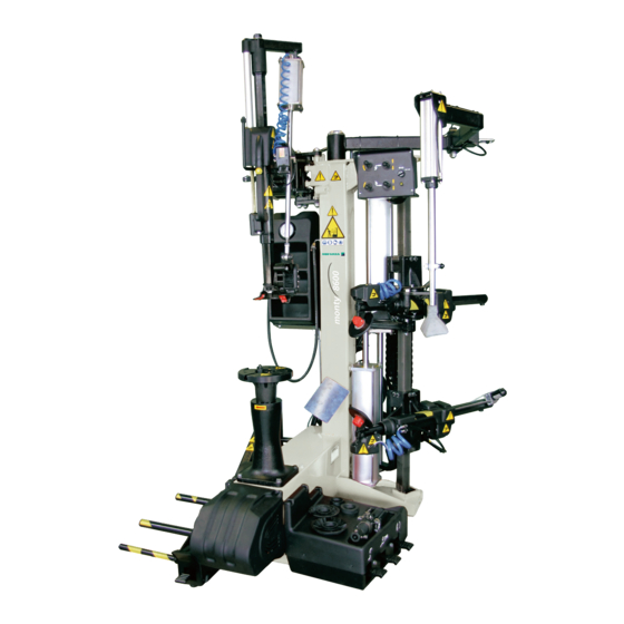
ATC 900 – CENTAUR –
MONTY 8600 – VULCAN PRO
SERVICE MANUAL
DO NOT COPY NOR DISTRIBUTE
No part of this document may be photocopied, reproduced, or translated
without prior written consent of Snap-on
1
CTC-CEN Service Manual 07-13 Rev.E
Table of
Contents
Previous
Page
Next
Page
1
2
3
4
5
Advertisement
Table of Contents
Need help?
Do you have a question about the ATC 900 and is the answer not in the manual?
Ask a question
Questions and answers
Related Manuals for Hofmann ATC 900
Wheel Balancers Hofmann AR 2400 Operator's Manual
(246 pages)
Wheel Balancers Hofmann geodyna 4500-2 Operation Manual
(129 pages)
Wheel Balancers Hofmann geodyna 7300 Operation Manual
(128 pages)
Wheel Balancers Hofmann VAS 6307 Operation Manual
(128 pages)
Wheel Balancers Hofmann Geodyna 8250p Operation Manual
(184 pages)
Wheel Balancers Hofmann geodyna 7600 Service Manual
(121 pages)
Wheel Balancers Hofmann POWER CLAMP features Additional Instructions
(33 pages)
Wheel Balancers Hofmann Snap-on Y2k Service Manual
(99 pages)
Wheel Balancers Hofmann geodyna 980 L Operation Manual
Wheel balancer for truck wheels (120 pages)
Wheel Balancers Hofmann geodyna 7100 Service Manual
(93 pages)
Wheel Balancers Hofmann geodyna OPTIMA II Operation Manual
Diagnostics wheel balancer (272 pages)
Wheel Balancers Hofmann Megaspin 800 Operating Instructions Manual
Electronic microprocessor wheel balancer with three-dimensional graphic visual display unit for car, commercial vehicle and motorcycle wheels (28 pages)
Wheel Balancers Hofmann geodyna optima Additional Instructions
(62 pages)
Wheel Balancers Hofmann geodyna 6800 Operation Manual
Wheel balancer (148 pages)
Wheel Balancers Hofmann geodyna 9000p Service Manual
(157 pages)
Wheel Balancers Hofmann geodyna 3900 Operation Manual
(132 pages)
This manual is also suitable for:
Monty 8600
Table of Contents
Save PDF
Print
Rename the bookmark
Delete bookmark?
Delete from my manuals?
Login
Sign In
OR
Sign in with Facebook
Sign in with Google
Upload manual
Upload from disk
Upload from URL


Need help?
Do you have a question about the ATC 900 and is the answer not in the manual?
Questions and answers