Table of Contents
Advertisement
HofmannIndustrial GmbH
A - 5302 Henndorf
Hauptstraße 59
Tel +43-6214-6466-12 \ Fax -22
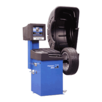
ELECTRONIC MICROPROCESSOR WHEEL BALANCER
WITH THREE-DIMENSIONAL GRAPHIC VISUAL DISPLAY
UNIT FOR CAR, COMMERCIAL VEHICLE AND
Visual
display unit
Control
panel
Flange
stakes
MOTORCYCLE WHEELS
0055 - 1998.12
Operating instruction manual
Weight and accessories table
( Series A )
Protection cover
Automatic distance + diameter
gauge
Pneumatic chuck lock
pedal
0055 - 1
( Series A )
Automatic
width reading
gauge
Wheel balancer
chuck
Parking and emergency
brake pedal
Advertisement
Table of Contents

Related Manuals for Hofmann Megaspin 800


Summary of Contents for Hofmann Megaspin 800
- Page 1 0055 - 1 HofmannIndustrial GmbH A - 5302 Henndorf Hauptstraße 59 Tel +43-6214-6466-12 \ Fax -22 ( Series A ) ( Series A ) ELECTRONIC MICROPROCESSOR WHEEL BALANCER WITH THREE-DIMENSIONAL GRAPHIC VISUAL DISPLAY UNIT FOR CAR, COMMERCIAL VEHICLE AND MOTORCYCLE WHEELS 0055 - 1998.12 Operating instruction manual Protection cover...
-
Page 2: Table Of Contents
2 - 0055 CONTENTS page 1- GENERAL DETAILS ..................................5 1.1 - GENERAL SAFETY PRECAUTIONS ........................... 5 1.1.1 - STANDARD SAFETY DEVICES ..........................5 1.2 - FIELD OF USE ................................5 1.3 - OVERALL DIMENSIONS ............................. 5 1.4 - TECHNICAL DETAILS ..............................6 2 - HANDLING, LIFTING ................................. - Page 3 0055 - 3...
- Page 4 4 - 0055 Note: Due to international agreements this machine may not be sold in the following countries: France, Germany, Italy, USA...
-
Page 5: 1- General Details
0055 - 5 1 - GENERAL DETAILS 1.1 - GENERAL SAFETY PRECAUTIONS - The wheel balancer must only be used by authorised and adequately trained personnel. - The wheel balancer must not be used for purposes other than those indicated in the manual - The wheel balancer must not be modified in any way, excepting modifications explicitly approved by the manufacturer - The safety devices must not be removed. -
Page 6: Technical Details
6 - 0055 1.4 - TECHNICAL DETAILS Weight with cover (excluding flange) ..... 138 kg model 800 ..............159 kg model 800P Single-phase power supply ......115-230 V 50-60 Hz Insulation class ..........IP 54 Max. power input ........... 500 W Monitor ............ -
Page 7: Setting Up
0055 - 7 3 - SETTING UP 3.1 - SECURING The machine can operate on any flat non-elastic surface. Makes sure only the 2 support points (fig. 3) actually touch the floor. If possible, we recommend securing the machine to the floor by means of the feet (see figure 3). 3.2 - POWER CONNECTIONS The machine features a single phase and earth lead. -
Page 8: Controls And Components
8 - 0055 4 - CONTROLS AND COMPONENTS 4.1 - BRAKE PEDAL Fig. 5 This enables the operator to hold the wheel fast during counterweight fitting. This must not be operated during the measurement cycle. 4.2 - PNEUMATIC LOCKING PEDAL (Model P) Fig. -
Page 9: Keyboard
0055 - 9 4.7 - KEYBOARD Fig. 7 Function keys: for immediate selection of functions shown on screen Special functions Confirm Measurement Machine cycle stop selection cycle start Note: Only press the keys with fingers; do not use counterweight pliers or other pointed tools. -
Page 10: Wheel Balancer Indications And Operation
10 - 0055 5 - WHEEL BALANCER INDICATIONS AND OPERATION The screen provides and shows various details, as well as numerous operating options for the operator. Such information is split into "frames" or "display pages". 5.1 - INITIAL FRAME Enabled keys MENU : main functions frame (see 5.2) : type of correction (see 5.5.4) -
Page 11: Menu Access Diagram
0055 - 11 5.2 - MENU ACCESS DIAGRAM " ... " Note: - the symbol indicates the presence of another menu HOME - to return to the previous menu, press key STOP MENU - to return to initial frame press key MENU User reference User reference... -
Page 12: Setting The Wheel Dimensions
12 - 0055 5.3 - SETTING THE WHEEL DIMENSIONS 5.3.1 AUTOMATIC SETTING Manual End The display page appears showing the distance+diameter measurement gauge. The "acquired dimension" indication is indicated by the symbol of the correction weight changing from blue to red. - Standard wheels: Using the special grip, move the end of the gauge against the rim, push the gripper upwards and wait for the weight symbol on the screen to change from blue to red. - Page 13 0055 - 13 - Set the nominal width, normally indicated on the rim, or determine the width "b" with the caliper provided. - Press button to return to the measurement frame "AUTOMATIC WIDTH" OPTION - Move both gauges to measuring position as shown below: Fig.
-
Page 14: Retrieving Stored Measurements
14 - 0055 Fig. 8D Fig. 8C Manual End - ALU-M wheel (correction from inside for two balancing levels with direct calibration) After measuring the inner sidewall FI, as shown in fig. 9, further remove the gauge to store the data of the outer sidewall FE. -
Page 15: Manual Setting
0055 - 15 5.3.3 - MANUAL SETTING (Only use in special cases or for checking) Unit If necessary, dimensions can be entered or changed manually as follows: MENU - press or press from automatic dimensions frame (accessible by pulling out the distance + diameter gauge);... -
Page 16: User Management
16 - 0055 5.4 - USER MANAGEMENT User save Cancel The wheel balancer can be used at the same time by 4 different users who, by means of a simple sequence can store their work condition and retrieve this in case of need. The names of the users can be stored (7.2) 5.4.1 - USER STORAGE - Correctly set the dimensions as already described at paragraphs 5.3.1 and 5.3.3... -
Page 17: 5.4 Measurement Result
0055 - 17 5.5 - MEASUREMENT RESULT Fine After making a balancing spin, the unbalance values are displayed along with arrows useful for positioning at the point of application of the correction weight. After positioning the wheel, fit the weight upwards along the vertical. -
Page 18: Indication Of Exact Position Of Correction Weights
18 - 0055 5.5.1 - INDICATION OF EXACT POSITION OF CORRECTION WEIGHTS It is always best to use this function for correcting unbalance using adhesive weights: ALU 1, ALU 2, ALU 3, ALU M. This function is designed to cancel any approximation in fitting counterweights, with consequent reduction of outstanding unbalance. -
Page 19: Split" Management
0055 - 19 5.5.2 - "SPLIT" MANAGEMENT SPLIT is only possible in the case of outer sidewall static or ALU-M unbalance. Its purpose is to hide any unbalance correction adhesive weights behind the spokes of the rim. input SETTING THE NUMBER OF RIM SPOKES - Press on the STATIC or ALU-M measurement panel;... -
Page 20: Imbalance Optimisation
20 - 0055 5.5.3 - UNBALANCE OPTIMISATION UNBALANCE OPTIMISATION IMPORTANT!!! The previous spin must have been made with the currently fitted wheels. Make a reference mark to indicate the rim-flange position in order to refit the rim on the flange in the same position. Remove the wheel from the wheel balancer. -
Page 21: Correcting Static Imbalance
0055 - 21 NORMAL Balancing steel or light-alloy rims with the fitting of weights with clips on the rim edges STATIC STATIC correction is required in the case of motorcycle wheels or when it is not possible to fit counterweights on the two sides of the rim ALU - 1 Balancing of light-alloy rims with the fitting of adhesive weights on the shoulder of the rims. -
Page 22: Run-Out Measurement (Optional)
22 - 0055 5.7 - RUN-OUT MEASUREMENT (OPTIONAL) The figures indicate the, much amplified, outer surface of the tyre and the wheel rotation axis. Fig. A Fig. A shows total Peak-Peak run-out Fig. B measurement, defined as maximum radial deviation of the tyre surface. Fig. -
Page 23: Setup
0055 - 23 6 - SETUP (See 5.2 - Menu access diagram) The Setup frame provides the user with numerous options for setting the machine according to his needs. All the settings remain unaltered even when the machine is switched off. The enabled buttons are : HOME STOP : return to previous window... -
Page 24: Calibration And Special Functions
24 - 0055 - ATTENTION - 7 - CALIBRATION AND SPECIAL FUNCTIONS (see access diagram 5.2) In order to access the "Settings and special functions", a password must be entered. Any wrong operation within the functions shown below could damage wheel balancer operation. Unauthorised use will invalidate the machine warranty. -
Page 25: Flange Run-Out Correction
0055 - 25 7.4.2 - FLANGE RUN-OUT CORRECTION This electronically compensates any systematic balancing error due, for instance, to flange run-out. It is not able to compensate for worn flanges or with play. Do not use unless advised to do so by skilled personnel. Follow the instructions shown on the screen. When this function is engaged, the icon appears in the lower part of the screen. -
Page 26: Errors
26 - 0055 8 - ERRORS Opened guard ERROR MEANING No rotation signal. This could be due to a faulty position transducer, to the motor not having started or to something stopping the wheel from turning. During spin, the speed drops below 60 1/min. Repeat the spin. Mathematical calculation error, very likely caused by incorrect self-calibration. -
Page 27: Routine Maintenance
0055 - 27 9 - ROUTINE MAINTENANCE 9.1 - SCHEDULED MAINTENANCE Before performing any maintenance operation, interrupt power to the machine 9.2 - REPLACING THE PROTECTION FUSES Accessible by removing the weight carrying table, the power and power supply board features 4 protection fuses (see exploded Tables, Item 317). - Page 28 Tipo - Nr. di serie / Type - Serial Number / Typ - Fabriknummer, usw / Type - Numero de série / Tipo - Numero de fabricacion/ af typen / Typ-Serienummer megaspin 800 - 800P A/B/C Manufacturing List Number-Erstellungsliste nummer-Numéro de liste de construction...
Need help?
Do you have a question about the Megaspin 800 and is the answer not in the manual?
Questions and answers