Table of Contents
Advertisement
Quick Links
Advertisement
Chapters
Table of Contents

Subscribe to Our Youtube Channel
Related Manuals for Hofmann Snap-on Y2k


Summary of Contents for Hofmann Snap-on Y2k
- Page 1 SERVICE of the Y2k balancing platform Seite 1 von 99...
-
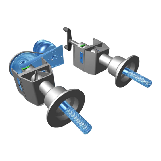
Page 2: The Vibratory Assemblies Of The Y2K Balancing Platform
The vibratory assemblies of the Y2k balancing platform R´ L´ M´ S´ Seite 2 von 99... - Page 3 New principle for vibratory system – designed to reduce the effects of force relations The disadvantages of the former solutions are the considerable effects of force relations. As a result the plane separator circuit mostly had to form the difference between high measured values in the transducer planes in order to calculate the unbalances present in the correction planes.
- Page 4 The dependence of the measured values L from distance ( a+b ) and R from distance ( a+b+c ) respectively becomes obvious from the straight lines in Fig. 1. They intersect the axis in the measuring planes. The forces in the measuring planes increase linearly with increasing distance.
- Page 5 Another possibility to reduce the effects of force relations is an increased distance between measuring planes as illustrated in Fig. 3. This condition is not always feasible for lack of space and makes sense to a limited extent only because the left-hand measuring signal is reduced and consequently the influence from fluctuations of measured values will increase.
- Page 6 Fig. 5 System with two virtual measuring planes outside of the physical range When the measuring planes are located in optimum positions, the virtual left-hand measuring plane is just inside the wheel disc when the wheel is as close as possible to the housing of the wheel balancer (see Fig.
- Page 7 vibration. If forces are applied left of the node of vibration such as illustrated in Fig. 7b the vibratory system will respond in the direction of the forces applied. If, however, the forces are applied in the node of vibration as illustrated in Fig. 7c the vibratory system will maintain a state of rest.
- Page 8 Fig. 8 Force measuring system with one virtual point of support In Fig. 9 two of the systems illustrated in Fig. 8 are arranged in series at different distances relative to the node of vibration. Consequently it is possible to establish a force measuring system for measurement of unbalances in two virtual measuring planes.
- Page 9 R´ L´ Fig. 10 Two systems arranged one above the other with different virtual points of support M´ S´ Fig. 11 Two systems arranged in series with a parallel pair of springs Seite 9 von 99...
- Page 10 M´ S´ Fig. 12 Two systems arranged one above the other with a parallel pair of springs Seite 10 von 99...
- Page 11 In case of alternatives as shown in Fig. 11 and 12 , a centrifugal force introduced in S will be detected by transducer S' only as long as transducer M' does not supply any signal. Irrespective of the distance of the introduced centrifugal force transducer S' will always supply a signal proportional to the quantity of the centrifugal force.
-
Page 12: Table Of Contents
The vibratory assemblies of the Y2k balancing platform Contents 15 The Vibratory assemblies.......................14 Variants of vibratory assemblies within the Y2k balancing platform ........14 15.1.1 Vibratory assembly for hand drive with fixed adaptor ...........15 15.1.2 Vibratory assembly for motor drive with fixed adaptor..........15 15.1.3 Vibratory assembly for motor drive with tapered shaft..........15 Removal and fitting of the vibratory assemblies ..............16 15.2 Unbalance transducers and temperature sensor.............16... - Page 13 Hints for the field engineer Please provide machine model, serial number and program version number with problem reports. If there are unstable unbalance readings, insufficient plane separation or weight chasing prob- lems, in addition to the vibratory assembly consider the following causes: a) Does the wheel slip on the adaptor? Chalk mark adaptor and rim.
-
Page 14: The Vibratory Assemblies
The Vibratory assemblies The vibratory assembly is the central module of a wheel balancer. It consists of the force guidance structure for directing the alternating unbalance forces via the transducers. The main shaft is supported on ball bearings in the vibratory tube with the wheel adaptor at the right-hand end. -
Page 15: Vibratory Assembly For Hand Drive With Fixed Adaptor
Snap-on P/N EAA0260D02A (used with b9750 ), HOFFMANN Mat-Nr. 6418868 used with HOFMANN geodyna 980 , 4300 und 4800 . Utilising tapered main shaft for various adaptors as customary with HOFMANN balancers. The shaft lock is of the mechanical design described under chapter 15.5.2.2. -
Page 16: Removal And Fitting Of The Vibratory Assemblies
Nm). 15.2 Unbalance transducers and temperature sensor Two transducers ( Snap-on P/N EAA0260D59A, HOFMANN Mat-Nr. 6717253) and the accompanying temperature sensor are used with all variants of the Y2k vibratory assemblies. The alternating forces, produced during rotation of the unbalance, are converted into a proportional electrical charge utilising the piezo effect. -
Page 17: Fitting And Pre-Stressing The Transducers
Screw on the locknut M10x1 (17-mm across the flats), but do not tie up yet. At the rigid support plate, a nut M10x1 of 5-mm thickness (Snap-on P/N 1-11833, HOFMANN Mat-Nr. 1556106), at the front with the slightly slant screw; a nut of 8-mm (Snap-on P/N1-4034, HOFMANN Mat-Nr. 1556101) is used. -
Page 18: Checking Continuity And The Relevant Insulation Resistance Of The Transducers
The temperature sensor is fixed to the vibratory plate by a u-shaped spring ( Snap-on P/N EAS2025D12A, HOFMANN Mat-Nr. 1628090). Electrical connection to the Controller board is via the AWG 28 ribbon cable harness and connector X3. -
Page 19: The Incremental Encoders
30 by 50 mm e.g. ″Tesa Nr.: 4651″ (HOFMANN Mat-Nr. 5198320). In the encoder IC on the Optoelectronic unit, behind a lens there is a red, in the direction of the main shaft, oblong Light Emitting Diode (LED). -
Page 20: Non-Volatile Memory At Optoelectronic Unit
The pattern of a code strip, fixed to the circumference of the big pulley, is sensed optically by an encoder board positioned 1-mm above the pulley. The adhesive code strip (Snap-on P/N EAM0005D64A, HOFMANN Mat-Nr. 6419096) consists of a transparent foil with alternating black and white zones (32 increments) printed CAUTION! The wider zone of the zero reference has to be positioned to the edge of the pulley. -
Page 21: The Drive Systems
The small pulley at the motor, the big pulley at the left end of main shaft and the Multirib belt ( Snap-on P/N 8-3531, HOFMANN Mat-Nr. 1252584) called mlti-vee belt as well. The screws fastening the motor to bracket are used for belt tensioning also. -
Page 22: Belt Tension
At reaching the pre-set speed, torque is cut back. The low torque is set to a rate, compensating the friction, for the most part, caused by the belt and by air drag of the wheel. Torque reduction is accomplished by lowering the voltage supplied to the motor with an AC controller, located on the Power Interface board. -
Page 23: The Brakes
used as pivots for the shaft lock, if provided). Insert a big screwdriver between the upper and rear distance bolts. Lift the handle of the screwdriver in order to push the motor backwards and tighten the upper screw (10-mm width across flats). The initial tension of a new Multirib belt should be set to 200 N (Newton). -
Page 24: Decelerating The Main Shaft By Pressing The Pedal
15.5.1.2 Decelerating the main shaft by pressing the pedal With the BOXER S1100 and HOFMANN geodyna 930, a mechanical foot operated brake is used for decelerating the main shaft after measurement and as the shaft lock (see chapter 15.5.2.1). -
Page 25: Adjusting The Air Gap
1) Shims inserted between the brake stator and the welded part of the vibratory assembly. For this, recommended alternative, at least two shims of 0.2-mm (HOFMANN Mat-Nr. 6417655) or 0.5-mm (HOFMANN Mat-Nr. 6417656) plate thickness must be available. 2) Removal of washers between the brake hub and support disc on the main shaft. -
Page 26: The Power-Clamping Device
0.5 Check that tie rod, clamping bolt and nut are sufficiently greased. CAUTION! Use ball bearing grease Klüberplex BEM34-132 (HOFMANN Mat-Nr. 1317060). Assemble all parts in reverse order and check the clearance. -
Page 27: Releasing A Wheel From The Power-Clamping Device In The Event Of A Power Failure
The pitch-to-diameter ratio of the clamping nut thread has been selected that self-locking occurs in the clamped state; i.e. the clamped state is retained. To carry out a measurement run, the motor M1 is switched on but with the main shaft is free to rotate. - Page 28 TO UPDATE /FLASH THE NEW SOFTWARE FOR THE NEW GENERATION WHEEL BALANCERS. 1. Digital Display Wheel Balancers. ( 930/980/4300/6300 – b9000/b9450/b9460) 2. Switch off the Wheel Balancer and Remove the weight tray . Then open up the Electronic Box inside the balancer . Insert the New Version Of Eprom ( as shown on attached page ).
- Page 29 Changing the program E-proms version Electronic view inside the machine Mark Eprom base Eprom mark Not used Seite 29 von 99...
- Page 30 Basic settings of the potentiometers Distance Diameter Width Gauge arm in home position; Gauge arm applied onto outher radius Gauge arm in home position on axial guide bushing of cone adaptor flange (185 mm diameter) on open wheel guard 1D- SAPE 4,25 - 4,30 Snap-on/ from front 1D- SAPE...
- Page 31 Electronics Box connections Seite 31 von 99...
- Page 33 How to configure the PCM-3350 bios The required BIOS configuration for the PCM-3350 is as follows: Standard CMOS-Setup please set manuel Standard CMOS Setup Primary master None Primary slave None Secondary master Auto Drive A None Drive B None Video EGA / VGA Halt on NO Errors...
- Page 34 Power Management Setup Power management disabled Standby mode disabled HDD power down disabled MODEM use IRQ Throttle duty cycle 33.3% PNP/PCI configuration PNP OS installed Resources controlled by auto Reset configuration data disabled PCI IRQ activated by level Integrated Peripherals IDE HDD block mode enabled Primary IDE channel...
- Page 35 Seite 35 von 99...
- Page 36 Service Some notes about the operations of the wheel balancer: All measured angular positions are related to the mass to balance the wheel; they are not the positions of the imbalance mass itself. If the balancer is in service mode, some of the normal behaviour is changed: •...
- Page 37 In Field Reprogramming of Balancer 1. Turn off balancer. 2. Place EEPROM in micro-controller socket with flat end at bottom of socket close to large blue connector. Notched end is 3 spaces short of other end of socket. 3. Turn on balancer. 4.
- Page 38 Recommended service steps In case of an error it is recommended to perform some service code to check the system. The following are some common service codes for this job. - Indicate the content of the error record • - Check the incremental encoder of the main shaft •...
- Page 39 Selftest during startup (CRT/HNA/HWT) A series of tests is accomplished after the machine has been turned on. If a test is not successful: a series of audible signals is given, or • an error code is read out. • On HNA/HWT or CRT models, a three-tone signal is given once, if the machine is operative. In case there is a functional error it must be acknowledged by pressing the STOP or ESC key and there is no three- tone signal.
- Page 40 Check pedal switches E 89 Affected models : Models with power clamp or electromagnetic brake : C56 to check the pedal switches. Service Codes C75, AdC16 to check voltage to external switches Models with solenoid brake only (e.g. 6300(p)): One or, if available, both pedal switches are actuated. The user can now remedy the trouble. Press STOP or ESC key to check the pedal switch once again and to delete the error code reading.
- Page 41 11. Check OPTIMA outer scanner E 364 Affected models : Models with optima hardware : All codes available for the model Service Codes Right side scanner self test fail or CCD not calibrated or zero mark not detected. Balancing is not possible since wheel data cannot be scanned. Problem during power up.
- Page 42 14.3 Hardware test - 5V line C 1 0 8 1 0 Affected models : All models C 1 0 8 1 1 Service Codes : C110 to heck 5V voltage. If the 5V voltage is below or above a limit the error code is displayed. Error ID Please refer to chapter 0 C 1 0 7 0 5...
- Page 43 18. Check home position of right SAPE Affected models : Models with 3D-P-SAPE : C82 to calibrate SAPE Service Codes Outer SAPE gauge arm not in home position. Re-place SAPE gauge arm in home position and press STOP or ESC key to continue. 19.
- Page 44 Error Codes H codes (CRT/HNA/HWT) ui_error.h revision 1.11 Internal code(s) Description Wheel running conditions cannot be improved by optimisation Further optimisation not recommended but feasible Weight minimisation is recommended, optimisation can achieve no further improvement The correction plane cannot be re-located using the gauge arm Indexing position does not match correction plane 0x492215 Unclamping of power clamp device is disabled...
- Page 45 E codes (CRT/HNA/HWT) ui_error.h revision 1.11 Internal code(s) Description Rim dimensions entered incorrectly Wheel guard is not closed Gauge arm not in home position Outer gauge arm not in home position Range of electrical unbalance compensation exceeded (residual adapter unbalance) 0x812560, 0x812561, Calibration weight not attached to flange 0x812565, 0x812566...
- Page 46 Internal code(s) Description E141 0x000169 Check sum of EEPROM 1 is wrong E144 0x00016D Check sums of both EEPROMs are wrong E145 0x000168 Contents of the EEPROMs are different E300 The microcontroller was not able to detect a keyboard. Check cabling between microcontroller and keyboard. E341 0x00016A Check sum of EEPROM 2 is wrong...
- Page 47 K codes (Kernel errors) ( s e e y 2 k b k c l r m . d o c r e v i s i o n 3 0 ) Structure of an error code A complete error code consists of 6 hexadecimal digits. Prefix Digit 6 Digit 5...
- Page 48 Mod. ID Description Power clamp Incremental potentiometer Rim light Balancing algorithm Balancing calibration Behind the spokes placement <not used> Optimisation Measurement control Command language (Commands coming from the UI) Calculator Message Server (Message service from BK to UI) Message Server (User messages from BK to UI) Sleep command Balancing Kernel : Test statemachine (eg selftest during startup) Event system...
- Page 49 Priority ID Prior. ID Description Critical error (will be recorded in user mode) Warning message For information only All of above, but will not be recorded in the error record (persistent objects p30 to p39) Error ID The table lists the error codes and gives some examples for an error. Error ID Limits Description Not complete...
- Page 50 Error ID Limits Description Bad medium Error in expression Mod C3, User Interface : Communication Error between balancing kernel and user interface (BK -> UI). This error can be cleared by pressing STOP or Escape. This error can caused by a bad connection of the RS232-E serial line.
- Page 51 Error ID Limits Description RS232-E : Wrong parameter for ioctl call. RS232-E : Input buffer overrun occurred RS232-E : Transmission error FIFO_KORRUPT FIFO_WRONG_ACTION FIFO_EMPTY_READ FIFO_FULL_WRITE FIFO_STRING_ENDE PIPE_NO_COMPLETE_MESSAGE_AVAILABLE SER_WRONG_ACTION SER_NO_HARDWARE SER_ERR_RESET_FIFO SER_ERRORCODE_EXISTS ERROR_PO_INIT_READORDER_FAILED ERROR_PO_INCORRECT_DATA_OR_HEADER_SIZE ERROR_PO_EEPROM_IS_FULL ERROR_PO_I2C_WRITE_ORDER ERROR_PO_NO_TIMECLIENT_AVAILABLE ERROR_PO_ORDER_IS_BUSY ERROR_PO_ORDER_IS_FULL ERROR_PO_PRODUCTION_READ_WRONG_TYPE ERROR_PO_EEP1_EEP2_ARE_DIFFERENT ERROR_PO_CRC_EEP1_ERROR ERROR_PO_CRC_EEP2_ERROR ERROR_PO_ORDER_HAS_FAILED...
- Page 52 Error ID Limits Description I2C_ERROR_NO_ACK_FROM_SEND2 2C_ERROR_NO_ACK_FROM_RECEIVE ERROR_I2C_SYNCHRONOUS_ORDER_TIMEOUT ERROR_I2C_ASYNCHRONOUS_ORDER_TIMEOUT ERROR_I2C_ORDER_HAS_FAILED ERROR_DS_USER_BREAK Drive system : Timeout during speed up - hand-spin only! speed does not settle after start command ERROR_DS_SPEED_NOT_REACHED Drive system : Speed slows down during measuring - speed falls below limit while measuring Drive system : Wheel speeds up in reverse turn - Hand-spin only! main shaft rotating backwards on start command Drive system : No acceleration during speed up or braking detected...
- Page 53 Error ID Limits Description During measuring run : Data conditioning can't get proper speed information. During measuring run : User break. (Measuring run stopped by user) During measuring run : Temperature information invalid, 20°C used instead. During measuring run : Can't perform transducer correction. Channel 1 - channel 2 Phase shift too big Transducer 1, No signal Transducer 1, transimpedance to low...
- Page 54 Error ID Limits Description Temperature below -30°C or hardware fault. -30°C Temperature above 100°C or hardware fault. 100°C Temperature Input near to ground Voltage. 0.23 V Temperature Input near to reference Voltage. 4.05 V Internal error : To many event sinks Internal error : Cannot register event sink Internal error : Invalid event level ERROR_IEMS_INV_PARAM...
- Page 55 Beep codes Abbreviations Beeps Frequency : 2000 Hz Duration : 100 ms Pause : 100 ms (Pause after beep, total length = 200 ms) Frequency : 1600 Hz Duration : 200 ms Pause : 400 ms Frequency : 1600 Hz Duration : 500 ms Pause...
- Page 56 Beep sequence Description Error during PO (persistent objects) based initialisation: S S P1 - Persistent objects initialisation - Bit field POs - Power on timer - Error recording - Incremental encoder of main shaft - External AD converter - Internal AD converter - Temperature measurement - Data conditioning - Balancing module...
- Page 57 Beep sequence Description Optimisation module L L 7S 1. Persistent object not available Counters L L 8S 1. Persistent object not available Extensions: - keyboard/display, SAPE, brake, motor 1. Persistent object not available 2. Resource not available (timer) Extensions: 3L S - Drive system 1.
- Page 58 C codes Table of C codes 1. Column "HWT/HNA indicates the C codes available to this date. The number behind the letter indicates the revision since this code is available. U : C code is available for the user : C code is available for service operator NA : C code will be discontinued CRT,HNA, Description...
- Page 59 CRT,HNA, Description JBEG Selecting the private brand 47 Select machine model 48 Download of application to FLASH memory. (Needs special software version) Please refer to chapter 0 "In Field Reprogramming of Balancer" for details how to program the balancer. Indication of voltage on distance analogue input Indication of voltage on diameter analogue input Indication of voltage on width analogue input 53 Display test - Only balancers with digital display...
- Page 60 CRT,HNA, Description JBEG 96 Indication of motor current. 97 Conditioning of the solenoid brake 98 Display of angular position of power clamp pulley, incremental encoder test (see C74). 99 Disabling the plane separation calculator. 100 Indication of the unbalance data in Cartesian coordinates. 101 Indication of the vibrations picked up by the unbalance transducers as an effective value.
- Page 61 Entering C codes and options CRT balancer In the function screen press the function selection button (F6) three times, then • C code press the appearing button "Service" to go to the service code menu. Press "C-Code" key (menu key) and turn wheel to choose a service code. •...
- Page 62 JBEG Digital balancer • The service menu is accessed by holding down the plus and minus keys for 7 seconds when the C code machine is idle. Note: The service menu is for service personnel only. Not for customers. The last service code used since power on is displayed.
- Page 63 John Bean Functional description The information relates up to software version 4.24 Note: Functional Requirements detailed in this document apply to B9000 (Handspin), B9450 (Low Digital) and B9460 (High Digital). Any model specific functionality is explicitly stated as model specific. Seite 63 von 99...
- Page 64 Table of Contents: Definition of Terms 1. Initialisation 2. Weight Placement Modes 3. Balancing Results Recalculation 4. Manual Data Entry 5. Weight Bar Operation 6. Sape Operation 7. Star Menu Access and Operation 8. Wheel Spin Functionality 9. Auto-Off Mode 10.
-
Page 65: Definition Of Terms
Definition of Terms JBEG John Bean Equipment Group, Balancer Brand Name Reference to the Snap-On common wheel balancer platform project B9000 JBEG handspin wheel balancer model designation B9450 JBEG entry level motorised (low-digital) wheel balancer model designator B9460 JBEG motorised (high-digital) wheel balancer model designator NORMAL A weight placement mode typically used for steel wheel rims. - Page 66 Figure 1. JBEG B9000 / B9450 User Interface Seite 66 von 99...
- Page 67 Figure 2. JBEG B9460 User Interface Seite 67 von 99...
-
Page 68: Initialisation
“C85” is diplayed. The user can use the plus and minus keys to select either C85 or C86. Pressing return causes the selected function to be executed and the machine to reset. C85 and C86 are used to synchronise the two flash chips. For a description see a Hofmann service manual. -
Page 69: Weight Placement Modes
2. Weight Placement Modes Figure 2. Weight placement positions 1 to 5. Nominal rim dimensions N1 to N3. The weight placement modes are described below. These modes are accessed by pressing the "weight" key. This cycles through the positions available. The order of the list is as follows; Normal, Alu1, Alu2, Alu3, Alu4, Hwm1, Hwm2, Static. -
Page 70: Balancing Results Recalculation
Weight Placement Quick Mode Holding down the weight placement key for 2 seconds results in a beep being generated and the weight placement selection mode being toggled between standard (the default) and quick mode. In quick mode the weight placement key cycles through NORMAL, HWM1 and HWM2 modes only. Upon machine power- on the selection mode active prior to power-down is restored. -
Page 71: Manual Data Entry
4. Manual Data Entry The nominal rim dimensions of the wheel can be entered by using the offset, width and diameter keys. These keys can be used when the balancer is idle. That is, there is no spin in progress and no other functions are in use. -
Page 72: Weight Bar Operation
5. Weight Bar Operation The weight bars indicate the direction required to rotate the wheel to bring the weight application position to the correct place for weight application. If there are no results displayed the bars rotate with the wheel (after encoder initialisation) but the green application led is never displayed. - Page 73 Non-HWM Sape Data Entry B9000/B9450 If the sape is held stationary for 1 second or more a beep is generated and the offset is shown in the left display panel. The value is removed from the display when the sape is returned to the home position. If a measuring run has been performed the results are recalculated and displayed when the sape is returned to the home position.
- Page 74 Sape Weight Application When valid results become available in a hwm mode, the sape is configured for weight application. When the sape is now removed from the home position the sape position is checked against the stored offset positions. The sape arm is used to apply stick on weights only. If a stick on weight is required for a plane, the value of the weight is above the threshold and the wheel is rotated so that the green application led is lit for that plane, the machine will beep when the sape arm is moved to within +/- 1.5mm of the weight position.
-
Page 75: Star Menu Access And Operation
7. Star Menu Access and Operation The star menu is accessed by pressing the star key while the machine is idle (idle defined above). The star led next to the key will light. There are four possible menu items in the star menu; swm, minimisation, oz and mm. The first selected item is determined as follows;... -
Page 76: Wheel Spin Functionality
8. Wheel Spin Functionality Common Features A wheel spin can be started when the machine is idle, when the star menu is active, when data is being entered manually and during user calibration, minimisation and some service codes. When the wheel spin starts the display is cleared of all data and a beep is generated. -
Page 77: Auto-Orientation / Sticky-On-Top
10. Auto-Orientation Mode / Sticky-On-Top B9460 Specific Features If C11 has been set to mode 1 or 2, the balancer will automatically brake to either the left or right weight application position after a measuring run. Pressing and releasing the PLUS key will auto-orientate the wheel into the weight application position for the other correction plane. -
Page 78: Weight Minimisation
12. Weight Minimisation All Models From version 4.00 weight minimisation has been replaced with Hofmann Weight minimisation / optimisation. All functionality is identical to existing Hofmann wheel balancers with the following key mappings. Hofmann Key JBEG Key STOP KEY STOP KEY... -
Page 79: User Management (B9450 / B9460 Only)
14. User Management (B9450 and B9460 only) User management enables the operator or operators to store 4 sets of preset data. The data stored are; rim offset, rim width, rim diameter, fine mode, weight placement mode, oz / gram section, mm / inch selection. -
Page 80: Service Menu
16. Service Menu The service menu is accessed by holding down the plus and minus keys for 7 seconds when the machine is idle. Note: The service menu is for service personnel only. Not for customers. The last service code used since power on is displayed. The service codes available can be accessed by using the plus and minus keys and selecting the desired code by pressing the return key. - Page 81 Unbalance compensation (B9000 Version) Displayed on selection: "C4" in left display, "0" or "1" in right display. Factory setting is "0". Step 1 options: A. Spin wheel to compensate for adaptor unbalance. The digit "1" is displayed in the left display to indicate the step number. All adaptors, cones and wheels must be removed from the machine shaft.
- Page 82 Unbalance compensation (B9450 / B9460 Version) Displayed on selection: "C4" in left display, "0" or "1" in right display. Factory setting is "0". Step 1 options: A. Spin wheel to compensate for adaptor unbalance. The digit "1" is displayed in the left display to indicate the step number. All adaptors, cones and wheels must be removed from the machine shaft.
- Page 83 Unbalance Threshold Suppression Displayed on selection: Suppression threshold in grams or ounces depending on selected display mode. Factory setting is 3.5g or equivalent. Step 1 options: Select the required threshold using the PLUS and MINUS keys. Press RETURN to confirm the value. Pressing the PLUS and MINUS keys together at any stage will act like an Escape key and exit the code without changing anything.
- Page 84 Counter Indication Displayed on selection: A 6-digit number is displayed across both displays (0 – 999,999). This number indicates the total number of measurement runs performed. Step 1 options: Pressing the PLUS or MINUS keys will display another counter. Four counters are available. These are; Counter 1 (C1): Total spins counter.
- Page 85 Display of the last 10 kernel error messages Displayed on selection: A 6 hex-digit error number is displayed across both displays. At two second intervals this number is switched with a number from 1 – 10 (1 being the most recent) indicating which error message is currently displayed.
- Page 86 Continuous Measuring Run (b9450 / B9460 only). Displayed on selection: "C63". Step 1 options: Lower the wheel hood to start the run. The wheel spins continuously and measuring results are displayed in grams periodically. Raise the hood at any stage to exit the code. Displaying Virtual Dimensions of the Vibratory System.
- Page 87 Continuous Measuring Runs With Pauses (b9450 / B9460 only). Displayed on selection: The digit "1" in the left display to indicate the step number. The first pause value in the right display. Step 1 options: Select the first pause period in seconds using the PLUS and MINUS keys. Confirm your selection using the RETURN key.
- Page 88 Measuring the Mechanical Phase Shift of the Vibratory System Displayed on selection: The digit "1" in the left display to indicate the step number. Step 1 options: Mount the factory calibration rotor on the balancer. Perform a measuring run. Step 2 options: The digit "2"...
- Page 89 Indication of the Position Counter Displayed on selection: A positive integer representing encoder increments (512 increments from 0 – 511). This represents the angular wheel position. If the wheel position subsystem is not initialised (possibly because the machine has just been turned on and the system requires at least one revolution to initialise) "buSY" is displayed until a value is available.
- Page 90 Indication of the drive system voltages (B9450 / B9460 only) Displayed on selection: A 3 digit voltage level is displayed in the right display. An identifier indicating which value is being shown, is displayed in the left display. Step 1 options: Pressing the PLUS and MINUS keys cycles through the list of values.
- Page 91 SAPE Arm Calibration (b9460) Displayed on selection: The digit "1" in the left display to indicate the step number. Step 1 options: Pressing the RETURN key will store the home position of the SAPE arm offset. Step 2 options: The digit "2" in the left display to indicate the step number. Pressing the RETURN key will store the fully extended position of the SAPE arm.
- Page 92 3D SAPE Arm Calibration (b9460) Displayed on selection: The digit "1" in the left display to indicate the step number. Step 1 options: Pressing the RETURN key will store the home position of the SAPE arm offset. Step 2 options: The digit "2"...
- Page 93 Adjustment of the Unbalance Measurement (Factory Calibration) Displayed on selection: The digit "1" in the left display to indicate the step number. Step 1 options: Mount the factory calibration rotor on the balancer. Perform a measuring run. Step 2 options: The digit "2"...
- Page 94 Compensation of the Residual Main Shaft Unbalance (B9000 version) NOTE: This code must be used after C83 is performed. The values produced are stored and used for every subsequent unbalance measurement where C4 is disabled. Displayed on selection: The digit "1" in the left display to indicate the step number. Step 1 options: All adaptors, cones and wheels must be removed from the machine shaft.
- Page 95 Copy Persistent Memory Contents from Controller Board to Opto. Board Displayed on selection: The service code number is shown. Step 1 options: Pressing the RETURN key will perform the memory copy and exit the service code. Pressing the PLUS and MINUS keys together at any stage will act like an Escape key and exit the code. Copy Persistent Memory Contents from Opto.
- Page 96 Compensation of the Residual Main Shaft Unbalance Mount a medium heavy wheel on the shaft. Enter the wheel data and balance the wheel (below 10 grams) in normal weight placement mode. Activate service code C88 from the service menu. Displayed on selection: The digit "1"...
-
Page 97: Factory Configuration Procedure
C111 Measure First harmonic of the belt (b9450 / b9460) Displayed on selection: A scrolling display appears in the left display panel. Step 1 options: Tap the belt (with a weight calipers for example). The balancer will beep to confirm that measuring has started. -
Page 98: Summary Of User Error Messages
19. Summary of user error messages Errors which can be generated during initialisation; SAPE arm not at home position 3D SAPE arm not at home position Error encountered during self test Errors which can be generated during a wheel spin are as follows; SAPE removed during wheel spin Speedup timeout Speed not reached... -
Page 99: In Field Reprogramming Of Balancer
20. In Field Reprogramming of Balancer 10. Turn off balancer. 11. Place EEPROM in micro-controller socket with flat end at bottom of socket close to large blue connector. Notched end is 3 spaces short of other end of socket. 12. Turn on balancer. 13.
Need help?
Do you have a question about the Snap-on Y2k and is the answer not in the manual?
Questions and answers