
Subscribe to Our Youtube Channel
Related Manuals for Lenze PROFIBUS E84AYCPM


Summary of Contents for Lenze PROFIBUS E84AYCPM
- Page 1 Accessories PROFIBUS® E84AYCPM Inverter Drives 8400 Communication Manual _ _ _ _ _ _ _ _ _ _ _ _ _ _ _ _ _ _ _ _ _ _ _ _...
-
Page 2: Table Of Contents
Free configuration of the port interconnection of process data objects (PDO) _ _ _ _ _ _ _ _ _ _ _ _ Lenze · E84AYCPM communication module (PROFIBUS®) · Communication Manual · DMS 5.0 EN · 11/2012 · TD17... - Page 3 12.2 Possible causes and remedies _ _ _ _ _ _ _ _ _ _ _ _ _ _ _ _ _ _ _ _ _ _ _ _ _ _ _ _ _ _ _ _ _ _ _ _ _ _ Lenze · E84AYCPM communication module (PROFIBUS®) · Communication Manual · DMS 5.0 EN · 11/2012 · TD17...
- Page 4 Your opinion is important to us _ _ _ _ _ _ _ _ _ _ _ _ _ _ _ _ _ _ _ _ _ _ _ _ _ _ _ _ _ _ _ _ _ _ _ _ _ Lenze · E84AYCPM communication module (PROFIBUS®) · Communication Manual · DMS 5.0 EN · 11/2012 · TD17...
-
Page 5: About This Documentation
All brand names used in this documentation are trademarks of their respective owners. Tip! Detailed information about PROFIBUS can be found on the website of the PROFIBUS & PROFINET user organisation: www.profibus.com Lenze · E84AYCPM communication module (PROFIBUS®) · Communication Manual · DMS 5.0 EN · 11/2012 · TD17... - Page 6 Engineering tools installed (»Engineer«, »STEP7«), the screenshots in this documentation may differ from the actual screen display. Lenze · E84AYCPM communication module (PROFIBUS®) · Communication Manual · DMS 5.0 EN · 11/2012 · TD17...
-
Page 7: Document History
• General revision 11/2010 TD17 General revision 11/2011 TD17 • New layout • New: Going online with »Engineer« via TCI ( 35) • General corrections Lenze · E84AYCPM communication module (PROFIBUS®) · Communication Manual · DMS 5.0 EN · 11/2012 · TD17... -
Page 8: Conventions Used
Optically highlighted reference to another page. Can be activated with a mouse-click in this online documentation. Step-by-step instructions Step-by-step instructions are indicated by a pictograph. Lenze · E84AYCPM communication module (PROFIBUS®) · Communication Manual · DMS 5.0 EN · 11/2012 · TD17... -
Page 9: Terminology Used
Programmable Logic Controller (German designation: SPS - Speicherprogrammierbare Steuerung) »STEP7« Siemens software for programming and configuring PROFIBUS Siemens control systems Software Tool Calling Interface Lenze · E84AYCPM communication module (PROFIBUS®) · Communication Manual · DMS 5.0 EN · 11/2012 · TD17... -
Page 10: Notes Used
Signal word Meaning Note! Important note to ensure trouble-free operation Tip! Useful tip for easy handling Reference to other documents Lenze · E84AYCPM communication module (PROFIBUS®) · Communication Manual · DMS 5.0 EN · 11/2012 · TD17... -
Page 11: Safety Instructions
• The procedural notes and circuit details described in this document are only proposals. It is up to the user to check whether they can be adapted to the particular applications. Lenze does not take any responsibility for the suitability of the procedures and circuit proposals described. -
Page 12: Device- And Application-Specific Safety Instructions
Protective insulation ( 16) Device protection The communication module contains electronic components which may be damaged or destroyed by electrostatic discharge. Installation ( 21) Lenze · E84AYCPM communication module (PROFIBUS®) · Communication Manual · DMS 5.0 EN · 11/2012 · TD17... -
Page 13: Product Description
Module type: communication module Type: PROFIBUS V/S V: coated version Ser.No.: S: standard version 2 Hardware version (HW) 3 Software version (SW) E84YCPM001E [3-1] Identification data Lenze · E84AYCPM communication module (PROFIBUS®) · Communication Manual · DMS 5.0 EN · 11/2012 · TD17... -
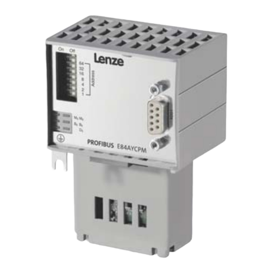
Page 14: Features
PROFIBUS connection ( 29) 5 LED status displays for diagnostics Module status displays ( 85) Fieldbus status displays ( 86) E84YCPM001C [3-2] E84AYCPM communication module (PROFIBUS) Lenze · E84AYCPM communication module (PROFIBUS®) · Communication Manual · DMS 5.0 EN · 11/2012 · TD17... -
Page 15: Technical Data
PNO identification number 0x0A89 Baud rate for cable type A (EN 50170) 9.6 kbps ... 12 Mbps (automatic detection) Conformities, approvals • CE • UL Lenze · E84AYCPM communication module (PROFIBUS®) · Communication Manual · DMS 5.0 EN · 11/2012 · TD17... -
Page 16: Protective Insulation
• the components to be connected must be provided with a second isolating distance. Note! The existing protective insulation in the Inverter Drives 8400 is implemented according to EN 61800-5-1. Lenze · E84AYCPM communication module (PROFIBUS®) · Communication Manual · DMS 5.0 EN · 11/2012 · TD17... - Page 17 X1 System bus (CANopen) X3 Analog inputs/outputs X4 Digital outputs X5 Digital inputs X6 Diagnostics MCI Slot for communication module MMI Slot for memory module Lenze · E84AYCPM communication module (PROFIBUS®) · Communication Manual · DMS 5.0 EN · 11/2012 · TD17...
- Page 18 • The separate potential area of the mains terminal has a "reinforced insulation". Result: The insulation between the mains terminal X100 and the bus terminal is of the "reinforced insulation" type. Lenze · E84AYCPM communication module (PROFIBUS®) · Communication Manual · DMS 5.0 EN · 11/2012 · TD17...
-
Page 19: Protocol Data
For some codes, the processing time may be longer (see software manual// »Engineer« online help for Inverter Drives 8400). There are no interdependencies between parameter data and process data. Lenze · E84AYCPM communication module (PROFIBUS®) · Communication Manual · DMS 5.0 EN · 11/2012 · TD17... -
Page 20: Dimensions
_ _ _ _ _ _ _ _ _ _ _ _ _ _ _ _ _ _ _ _ _ _ _ _ _ _ _ _ _ _ _ _ _ _ _ _ _ _ _ _ _ _ _ _ _ _ _ _ _ _ _ _ _ _ _ _ _ _ _ _ _ _ _ _ Dimensions E84YCPM001B [4-2] Dimensions Dimensions in mm Lenze · E84AYCPM communication module (PROFIBUS®) · Communication Manual · DMS 5.0 EN · 11/2012 · TD17... -
Page 21: Installation
• The communication module is defective. • Communication via the fieldbus is not possible or faulty. Protective measures Discharge electrostatic charges before touching the module. Lenze · E84AYCPM communication module (PROFIBUS®) · Communication Manual · DMS 5.0 EN · 11/2012 · TD17... -
Page 22: Mechanical Installation
2. Loosen the securing screw for the communication module on the standard device (3). 3. Insert the communication module into the MCI slot of the standard device (4). 4. Fasten the securing screw (5). Lenze · E84AYCPM communication module (PROFIBUS®) · Communication Manual · DMS 5.0 EN · 11/2012 · TD17... -
Page 23: Mounting For Standard Devices Of 0.55 Kw And More
3. Loosen the securing screw for the communication module on the standard device (3). 4. Insert the communication module into the MCI slot of the standard device (4). 5. Fasten the securing screw (5). Lenze · E84AYCPM communication module (PROFIBUS®) · Communication Manual · DMS 5.0 EN · 11/2012 · TD17... -
Page 24: Replacing The Communication Module
2. Remove the communication module from the MCI slot of the standard device (2). 3. Insert the new communication module into the MCI slot of the standard device (3). 4. Fasten the securing screw (4). Lenze · E84AYCPM communication module (PROFIBUS®) · Communication Manual · DMS 5.0 EN · 11/2012 · TD17... -
Page 25: Electrical Installation
The bus termination is supplied by the station itself. Stop! The bus terminator must always be supplied. Otherwise, the bus can get unstable. Lenze · E84AYCPM communication module (PROFIBUS®) · Communication Manual · DMS 5.0 EN · 11/2012 · TD17... - Page 26 Repeaters can be used to build up line and tree topologies. The maximum total bus system expansion depends on ... • the baud rate used; • the number of repeaters used. Lenze · E84AYCPM communication module (PROFIBUS®) · Communication Manual · DMS 5.0 EN · 11/2012 · TD17...
-
Page 27: Activating The Bus Terminating Resistor
Please observe that the bus termination is not active any longer if ... • the bus connector has been disconnected; • the voltage supply of the Inverter Drive 8400 has been switched off. Lenze · E84AYCPM communication module (PROFIBUS®) · Communication Manual · DMS 5.0 EN · 11/2012 · TD17... -
Page 28: Bus Cable Specification
• Bus lengths of several kilometres are also possible with higher baud rates. • The bus length is ... • independent of the baud rate; • dependent on the optical fibre used. Lenze · E84AYCPM communication module (PROFIBUS®) · Communication Manual · DMS 5.0 EN · 11/2012 · TD17... -
Page 29: Profibus Connection
Data ground (ground to 5 V) P5V2 5 V DC / 30 mA (bus termination) Not assigned RxD/TxD-N Data line A (received data/transmitted data, minus) Not assigned Lenze · E84AYCPM communication module (PROFIBUS®) · Communication Manual · DMS 5.0 EN · 11/2012 · TD17... -
Page 30: Commissioning
• whether the bus system is terminated by means of a bus terminating resistor at the first and last physical bus station. Activating the bus terminating resistor ( 27) Lenze · E84AYCPM communication module (PROFIBUS®) · Communication Manual · DMS 5.0 EN · 11/2012 · TD17... -
Page 31: Configuration Of The Controller (Master)
• "PCD (8W cons)" = 8 process data words Tip! A detailed description of consistency is given in the chapter "Consistent parameter data" ( 80) Lenze · E84AYCPM communication module (PROFIBUS®) · Communication Manual · DMS 5.0 EN · 11/2012 · TD17... -
Page 32: Setting The Station Address
• C13864: Display of the station address active on the PROFIBUS Note! Switch off the voltage supply of the communication module and then on again in order to activate changed settings. Lenze · E84AYCPM communication module (PROFIBUS®) · Communication Manual · DMS 5.0 EN · 11/2012 · TD17... - Page 33 Impermissible addresses are displayed in red in the Station address (code C13899). Save the changed settings with device command C00002/11 (save all parameter sets). Lenze · E84AYCPM communication module (PROFIBUS®) · Communication Manual · DMS 5.0 EN · 11/2012 · TD17...
-
Page 34: Initial Switch-On
• To enable the device directly at power-on, bit 0 must be set to zero (FALSE). • An uncontrolled restart of the drive is possible. Lenze · E84AYCPM communication module (PROFIBUS®) · Communication Manual · DMS 5.0 EN · 11/2012 · TD17... -
Page 35: Going Online With "Engineer" Via Tci
1. Allocate names for the individual axes in the »Engineer« project. In our case, "9400" was allocated for 9400 HighLine, and "8400" for 8400 StateLine: Lenze · E84AYCPM communication module (PROFIBUS®) · Communication Manual · DMS 5.0 EN · 11/2012 · TD17... - Page 36 • The selection of the process data configuration has no impact on TCI communication. 3. Establish an Ethernet connection to the PROFIBUS CPU. Lenze · E84AYCPM communication module (PROFIBUS®) · Communication Manual · DMS 5.0 EN · 11/2012 · TD17...
- Page 37 6. By double-clicking the PG/PC station inserted, open its "Properties" dialog. 7. Under the Interfaces tab, select a new Ethernet interface and confirm the selection with Lenze · E84AYCPM communication module (PROFIBUS®) · Communication Manual · DMS 5.0 EN · 11/2012 · TD17...
- Page 38 Ethernet connection that has been configured in the »HW Konfig«). In our case this is the Ethernet(1) connection: 9. Confirm the selection with OK. The connection has been accepted. Lenze · E84AYCPM communication module (PROFIBUS®) · Communication Manual · DMS 5.0 EN · 11/2012 · TD17...
- Page 39 10. Select the actual PG/PC connection under the Assignment tab. The connection highlighted is assigned by means of the Assign button. 11. Confirm the following message with OK. Lenze · E84AYCPM communication module (PROFIBUS®) · Communication Manual · DMS 5.0 EN · 11/2012 · TD17...
- Page 40 12. After the assignment, the connection appears in the "Assigned" display area. Close the dialog with OK. 13. In the »STEP7« project, the PG/PC station is marked with a yellow arrow. (The connection selected is active.) Lenze · E84AYCPM communication module (PROFIBUS®) · Communication Manual · DMS 5.0 EN · 11/2012 · TD17...
- Page 41 • If you confirm the message with Yes, the applicable TCI communication parameter settings of the »STEP7« project are transferred to the »Engineer«. Lenze · E84AYCPM communication module (PROFIBUS®) · Communication Manual · DMS 5.0 EN · 11/2012 · TD17...
- Page 42 Here the communication settings have been carried out successfully. The individual PROFIBUS addresses in the respective codes have been adapted to the »STEP7« project. Lenze · E84AYCPM communication module (PROFIBUS®) · Communication Manual · DMS 5.0 EN · 11/2012 · TD17...
- Page 43 • Use the Connect button to establish an online connection. • By means of the Search/Enter button, you can update the TCI communication parameters. Lenze · E84AYCPM communication module (PROFIBUS®) · Communication Manual · DMS 5.0 EN · 11/2012 · TD17...
-
Page 44: Data Transfer
• Parameter data are, for instance, operating parameters, diagnostic information, and motor data. • Parameter changes must be saved by means of code C00002 of the Inverter Drive 8400. Lenze · E84AYCPM communication module (PROFIBUS®) · Communication Manual · DMS 5.0 EN · 11/2012 · TD17... -
Page 45: Process Data Transfer
• The port/function block interconnection of the process data objects (PDO) takes place via the Lenze »Engineer«. [8-1] External and internal data transfer between the bus system, inverter, and function block interconnection Lenze · E84AYCPM communication module (PROFIBUS®) · Communication Manual · DMS 5.0 EN · 11/2012 · TD17... -
Page 46: Preconfigured Port Interconnection Of The Process Data Objects (Pdo)
C00007 = "40: MCI". It is possible to display the port blocks "LP_MciIn" and "LP_MciOut" as well as the preconfigured interconnections in the »FB Editor« : Lenze · E84AYCPM communication module (PROFIBUS®) · Communication Manual · DMS 5.0 EN · 11/2012 · TD17... -
Page 47: Free Configuration Of The Port Interconnection Of Process Data Objects (Pdo)
2. Go to the Ports tab and select the port block "MCI_IN" or "MCI_OUT" via mouse-click. Activate it by clicking Activate. 3. Click the Edit port ... button. Lenze · E84AYCPM communication module (PROFIBUS®) · Communication Manual · DMS 5.0 EN · 11/2012 · TD17... - Page 48 Assignment Signal --> Function Block dialog box. Select the signals and then confirm the selection with OK. Lenze · E84AYCPM communication module (PROFIBUS®) · Communication Manual · DMS 5.0 EN · 11/2012 · TD17...
- Page 49 For the process data words WORD_1 and WORD_2, you can also assign signals to the individual control bits and status bits via the buttons. Select the signals and then confirm the selection with OK. ü Lenze · E84AYCPM communication module (PROFIBUS®) · Communication Manual · DMS 5.0 EN · 11/2012 · TD17...
- Page 50 If the port blocks "LP_MciIn" and "LP_MciOut" are activated (see step 1), they are displayed in the »FB Editor«. Here you can also assign signals to the process data words. Lenze · E84AYCPM communication module (PROFIBUS®) · Communication Manual · DMS 5.0 EN · 11/2012 · TD17...
-
Page 51: Parameter Data Transfer
• PROFIBUS-DP index = 0x5FFF - 0x69 = 0x5F96 The parameter values are entered into the user data (bytes 5 to 8) of the telegram. Lenze · E84AYCPM communication module (PROFIBUS®) · Communication Manual · DMS 5.0 EN · 11/2012 · TD17... -
Page 52: Drivecom Parameter Data Channel (Dp-V0)
High byte Low byte Error 4 Error 3 Error 2 Error 1 The individual bytes are described in detail in the following subchapters. Lenze · E84AYCPM communication module (PROFIBUS®) · Communication Manual · DMS 5.0 EN · 11/2012 · TD17... -
Page 53: Byte 1: Service
• The set status bit indicates that the telegram is an "error telegram". The data of bytes 5 ... 8 (data/ error) must be interpreted as an error message. Error codes ( 58) Lenze · E84AYCPM communication module (PROFIBUS®) · Communication Manual · DMS 5.0 EN · 11/2012 · TD17... -
Page 54: Reading Parameter Data From The Inverter
• Status bit is not set: The write request has been executed correctly. • Status bit is set: The write request has not been executed correctly. The "Data/Error" field contains the Error codes ( 58) Lenze · E84AYCPM communication module (PROFIBUS®) · Communication Manual · DMS 5.0 EN · 11/2012 · TD17... -
Page 55: Abort Of Data Transfer By The Inverter
Byte 5 Byte 6 Byte 7 Byte 8 Service SIDX IDXH IDXL Error Class Error code Additional Additional Code High Code Low 1t110000 Lenze · E84AYCPM communication module (PROFIBUS®) · Communication Manual · DMS 5.0 EN · 11/2012 · TD17... -
Page 56: Byte 2: Subindex
Subindex 0x5F 0x96 Data 4 / Data 3 / Data 2 / Data 1 / Error 4 Error 3 Error 2 Error 1 Lenze · E84AYCPM communication module (PROFIBUS®) · Communication Manual · DMS 5.0 EN · 11/2012 · TD17... -
Page 57: Bytes 5
Byte 6 Byte 7 Byte 8 Parameter value (length 1) 0x00 0x00 0x00 Parameter value (length 2) 0x00 0x00 Parameter value (length 4) Lenze · E84AYCPM communication module (PROFIBUS®) · Communication Manual · DMS 5.0 EN · 11/2012 · TD17... -
Page 58: Error Codes
0x30 Value ranged exited 0x08 0x00 0x31 Parameter value too high 0x08 0x00 0x32 Parameter value too low 0x08 0x00 0x80 Hardware error Lenze · E84AYCPM communication module (PROFIBUS®) · Communication Manual · DMS 5.0 EN · 11/2012 · TD17... -
Page 59: Telegram Examples
Data 2 Data 1 High byte Low byte 0x11 0x00 0x5F 0xC2 0x00 0x2B 0x00 0x00 0t010001 00000000 01011111 11000010 00000000 00101011 00000000 00000000 Lenze · E84AYCPM communication module (PROFIBUS®) · Communication Manual · DMS 5.0 EN · 11/2012 · TD17... -
Page 60: Write Request: Setting The Deceleration Time For Quick Stop (Qsp)
Data 2 Data 1 High byte Low byte 0x40 0x00 0x5F 0x96 0x00 0x00 0x00 0x32 0t000000 00000000 01011111 10010110 00000000 00000000 00000000 00110010 Lenze · E84AYCPM communication module (PROFIBUS®) · Communication Manual · DMS 5.0 EN · 11/2012 · TD17... -
Page 61: Profidrive Parameter Data Channel (Dp-V1)
• No spontaneous messages are transferred. • There are only acyclic parameter requests. • Profile-specific parameters can be read independently of the slave state. Lenze · E84AYCPM communication module (PROFIBUS®) · Communication Manual · DMS 5.0 EN · 11/2012 · TD17... -
Page 62: Connection Establishment Between Master And Slave
Master DPV1- class 1 parameter data channel Read Slave Write Master class 2 E94YCPM010 [9-2] Data communication via the DP-V1 parameter data channel Lenze · E84AYCPM communication module (PROFIBUS®) · Communication Manual · DMS 5.0 EN · 11/2012 · TD17... -
Page 63: Acyclic Data Transfer
• The slave responds with "Read.res (-)" if processing has not yet been completed. • After parameter processing, the parameter request is completed by transmitting the parameter response to the master with "Read.res (+)". Lenze · E84AYCPM communication module (PROFIBUS®) · Communication Manual · DMS 5.0 EN · 11/2012 · TD17... -
Page 64: Telegram Structure
1 byte 0x00 2 bytes High byte Low byte 4 bytes High word Low word High byte Low byte High byte Low byte Lenze · E84AYCPM communication module (PROFIBUS®) · Communication Manual · DMS 5.0 EN · 11/2012 · TD17... -
Page 65: Reading Parameter Data From The Inverter
Low byte High byte Low byte Field Data type Values Index 0x0001 ... 0xFFFF (1 ... 65535) Subindex 0x0001 ... 0xFFFF (1 ... 65535) Lenze · E84AYCPM communication module (PROFIBUS®) · Communication Manual · DMS 5.0 EN · 11/2012 · TD17... -
Page 66: Response To A Correctly Executed Read Request
0x01 or number of requested subindices/parameters (with several subindices/parameters only the parameter value is repeated). In the case of string codes, the number of characters is entered here. Lenze · E84AYCPM communication module (PROFIBUS®) · Communication Manual · DMS 5.0 EN · 11/2012 · TD17... - Page 67 Field Data type Values Value String Any (length > 4 bytes possible) 0x00 ..0xFF 0x0000 ..0xFFFF 0x0000 0000 ..0xFFFF FFFF Lenze · E84AYCPM communication module (PROFIBUS®) · Communication Manual · DMS 5.0 EN · 11/2012 · TD17...
-
Page 68: Response To A Read Error
Number of values Field Data type Values Format 0x44: Error Number of values 0x01: Error code without additional information 0x02: Error code with additional information Lenze · E84AYCPM communication module (PROFIBUS®) · Communication Manual · DMS 5.0 EN · 11/2012 · TD17... - Page 69 Low byte High byte Low byte Field Data type Values Error code 0x0000 ..0xFFFF Error codes ( 74) Additional information (if available) Lenze · E84AYCPM communication module (PROFIBUS®) · Communication Manual · DMS 5.0 EN · 11/2012 · TD17...
-
Page 70: Writing Parameter Data To The Inverter
Low byte High byte Low byte Field Data type Values Index 0x0001 ... 0xFFFF (1 ... 65535) Subindex 0x0001 ... 0xFFFF (1 ... 65535) Lenze · E84AYCPM communication module (PROFIBUS®) · Communication Manual · DMS 5.0 EN · 11/2012 · TD17... - Page 71 Field Data type Values Value String Any (length > 4 bytes possible) 0x00 ..0xFF 0x0000 ..0xFFFF 0x0000 0000 ..0xFFFF FFFF Lenze · E84AYCPM communication module (PROFIBUS®) · Communication Manual · DMS 5.0 EN · 11/2012 · TD17...
-
Page 72: Response To A Correctly Executed Write Request
Mirrored value of the parameter request Response identification 0x02: Parameter has been written Axis 0x00 or 0x01 Number of indices 0xn (n = number of parameter addressed) Lenze · E84AYCPM communication module (PROFIBUS®) · Communication Manual · DMS 5.0 EN · 11/2012 · TD17... -
Page 73: Response To A Write Error
Low byte High byte Low byte Field Data type Values Error code 0x0000 ..0xFFFF Error codes ( 74) Additional information (if available) Lenze · E84AYCPM communication module (PROFIBUS®) · Communication Manual · DMS 5.0 EN · 11/2012 · TD17... -
Page 74: Error Codes
Write request: Number of values of the parameter consistent data do not match the number of subindices in the parameter address 0x0019 Reserved 0x0064 Lenze · E84AYCPM communication module (PROFIBUS®) · Communication Manual · DMS 5.0 EN · 11/2012 · TD17... - Page 75 _ _ _ _ _ _ _ _ _ _ _ _ _ _ _ _ _ _ _ _ _ _ _ _ _ _ _ _ _ _ _ _ _ _ _ _ _ _ _ _ _ _ _ _ _ _ _ _ _ _ _ _ _ _ _ _ _ _ _ _ _ _ _ _ Error code Description Explanation Additional information 0x0065 Manufacturer-specific 0x00FF Lenze · E84AYCPM communication module (PROFIBUS®) · Communication Manual · DMS 5.0 EN · 11/2012 · TD17...
-
Page 76: Telegram Examples
Byte 8 Value High byte Low byte 0x00 0x2B Value read = 0x 00 2B = 43 x 1 (internal factor) = 43 [°C] Lenze · E84AYCPM communication module (PROFIBUS®) · Communication Manual · DMS 5.0 EN · 11/2012 · TD17... - Page 77 Error code without additional information Byte 7 Byte 8 Error code High byte Low byte For the meaning, see the "Error codes" ( 74) chapter Lenze · E84AYCPM communication module (PROFIBUS®) · Communication Manual · DMS 5.0 EN · 11/2012 · TD17...
-
Page 78: Write Request: Setting The Deceleration Time For Quick Stop (Qsp)
Byte 3 Byte 4 Request reference Response identification Axis Number of indices (mirrored) (mirrored) 0xXX 0x02 0x00 0x01 Parameter has been written 1 index Lenze · E84AYCPM communication module (PROFIBUS®) · Communication Manual · DMS 5.0 EN · 11/2012 · TD17... - Page 79 Error code without additional information Byte 7 Byte 8 Error code High byte Low byte For the meaning, see the Error codes ( 74) Lenze · E84AYCPM communication module (PROFIBUS®) · Communication Manual · DMS 5.0 EN · 11/2012 · TD17...
-
Page 80: Consistent Parameter Data
Configuring consistent data Note! Consistency is achieved by an appropriate PROFIBUS master configuration. For this purpose, refer to the documentation for your configuring software. Lenze · E84AYCPM communication module (PROFIBUS®) · Communication Manual · DMS 5.0 EN · 11/2012 · TD17... -
Page 81: Monitoring
If one of these preconditions is not met, the response to the absence of cyclic process data telegrams from the master is not executed. Settings and displays in the »Engineer« ( 83) Lenze · E84AYCPM communication module (PROFIBUS®) · Communication Manual · DMS 5.0 EN · 11/2012 · TD17... -
Page 82: Short-Time Interruption Of Profibus Communication
Observe the following condition for the time setting: Monitoring time for the data exchange (C13881) watchdog monitoring time of the ≤ PROFIBUS (C13882/1). Lenze · E84AYCPM communication module (PROFIBUS®) · Communication Manual · DMS 5.0 EN · 11/2012 · TD17... -
Page 83: Settings And Displays In The "Engineer
• The Lenze setting "0" means that the diagnostic bit is not set for the following error responses. • An advanced diagnostic message is always sent. Lenze · E84AYCPM communication module (PROFIBUS®) · Communication Manual · DMS 5.0 EN · 11/2012 · TD17... -
Page 84: Diagnostics
( 86) ( 86) permanently. The following status displays are distinguished: • Module status displays ( 85) • Fieldbus status displays ( 86) Lenze · E84AYCPM communication module (PROFIBUS®) · Communication Manual · DMS 5.0 EN · 11/2012 · TD17... -
Page 85: Module Status Displays
The communication module is not accepted by the standard device or the standard device is not active. (See notes in the documentation for the standard device.) Lenze · E84AYCPM communication module (PROFIBUS®) · Communication Manual · DMS 5.0 EN · 11/2012 · TD17... -
Page 86: Fieldbus Status Displays
Incorrect setting for the station address. The communication module is initialised and internally operates with the respective default values. Bus error/fault is active (e.g. bus cable unplugged). Lenze · E84AYCPM communication module (PROFIBUS®) · Communication Manual · DMS 5.0 EN · 11/2012 · TD17... -
Page 87: Diagnosing With The "Engineer
_ _ _ _ _ _ _ _ _ _ _ _ _ _ _ _ _ _ _ _ _ _ _ _ _ _ _ _ _ _ _ _ _ _ _ _ _ _ _ _ _ _ _ _ _ _ _ _ _ _ _ _ _ _ _ _ _ _ _ _ _ _ _ _ 11.2 Diagnosing with the »Engineer« In the »Engineer«, the Diagnostics tab displays various pieces of PROFIBUS diagnostic information. Lenze · E84AYCPM communication module (PROFIBUS®) · Communication Manual · DMS 5.0 EN · 11/2012 · TD17... - Page 88 1.5 Mbps 500 kbps 187.5 kbps 93.75 kbps 45.45 kbps 19.2 kbps 9.6 kbps Bit 15 Bit 14 Bit 13 Bit 12 Reserved Lenze · E84AYCPM communication module (PROFIBUS®) · Communication Manual · DMS 5.0 EN · 11/2012 · TD17...
-
Page 89: Advanced Diagnostic Message
• Code C00165 can be used to read out the contents of the fault memory. • Detailed information regarding the error codes of the Inverter Drive 8400 can be found in the documentation of the inverter. Lenze · E84AYCPM communication module (PROFIBUS®) · Communication Manual · DMS 5.0 EN · 11/2012 · TD17... - Page 90 In the "Current" subject area, an overcurrent has been detected. The error response to this is a "Warning locked", which must be unlocked separately after the error has been eliminated. Lenze · E84AYCPM communication module (PROFIBUS®) · Communication Manual · DMS 5.0 EN · 11/2012 · TD17...
-
Page 91: Error Messages
No response C13880/1 0x01bc8131 33073 Profibus: Data_Exchange state exited No response C13880/1 0x01bc8132 33074 Profibus Watchdog: DP-V1 MSC2 monitoring time No response C13880/2 exceeded Lenze · E84AYCPM communication module (PROFIBUS®) · Communication Manual · DMS 5.0 EN · 11/2012 · TD17... -
Page 92: Possible Causes And Remedies
System fault Fault Trouble Quick stop by trouble Warning locked Warning Information Cause Remedy Module defective. If this occurs repeatedly, contact the Lenze service. Lenze · E84AYCPM communication module (PROFIBUS®) · Communication Manual · DMS 5.0 EN · 11/2012 · TD17... - Page 93 Quick stop by trouble Warning locked Warning Information Cause Remedy Access to parameter set was not successful. Repeat the download of the application (including module). Lenze · E84AYCPM communication module (PROFIBUS®) · Communication Manual · DMS 5.0 EN · 11/2012 · TD17...
- Page 94 Permanent interruption of communication to C2- Check cables and terminals. PROFIBUS master. Also see the chapter "Permanent interruption of PROFIBUS communication" ( 81). Lenze · E84AYCPM communication module (PROFIBUS®) · Communication Manual · DMS 5.0 EN · 11/2012 · TD17...
-
Page 95: Parameter Reference
Display area (min. value | unit | max. value) 65535 Subcodes Info C13851/1 C13851/16 Read access Write access CINH PLC-STOP No transfer PDO_MAP_RX PDO_MAP_TX Lenze · E84AYCPM communication module (PROFIBUS®) · Communication Manual · DMS 5.0 EN · 11/2012 · TD17... - Page 96 DRIVECOM parameter data channel • 0: Not active • 1: Active C13860/4 Reserved Read access Write access CINH PLC-STOP No transfer PDO_MAP_RX PDO_MAP_TX Lenze · E84AYCPM communication module (PROFIBUS®) · Communication Manual · DMS 5.0 EN · 11/2012 · TD17...
- Page 97 5 187.50 kbps 6 93.75 kbps 7 45.45 kbps 8 19.20 kbps 9 9.60 kbps Read access Write access CINH PLC-STOP No transfer PDO_MAP_RX PDO_MAP_TX Lenze · E84AYCPM communication module (PROFIBUS®) · Communication Manual · DMS 5.0 EN · 11/2012 · TD17...
- Page 98 = 29D7 C13864 | Active station address Display of the active station address If all DIP switches 1 ... 64 are in the "OFF" position (Lenze setting), the station address set in C13899 becomes active and is displayed here after switching on.
- Page 99 Setting range Lenze setting (min. value | unit | max. value) 65535 65535 ms Read access Write access CINH PLC-STOP No transfer PDO_MAP_RX PDO_MAP_TX Lenze · E84AYCPM communication module (PROFIBUS®) · Communication Manual · DMS 5.0 EN · 11/2012 · TD17...
- Page 100 • The diagnostic bit is sent to the PROFIBUS master where it is evaluated separately. • The diagnostic bit is always set when a system error occurs. • The Lenze setting "0" means that the diagnostic bit is not set for the following error responses. • An advanced diagnostic message is always sent.
- Page 101 C13887 | Suppress signalling diag. mess. upon Selection of the error responses not causing a diagnostic request to the PROFIBUS master. The Lenze setting "0" means that for each of the following error responses a diagnostic request is signalled. Value is bit-coded:...
- Page 102 Setting the station address ( 32) Display area (min. value | unit | max. value) Read access Write access CINH PLC-STOP No transfer PDO_MAP_RX PDO_MAP_TX Lenze · E84AYCPM communication module (PROFIBUS®) · Communication Manual · DMS 5.0 EN · 11/2012 · TD17...
-
Page 103: Table Of Attributes
1000 ≡ 3 decimal positions Access Read access Reading permitted Write access Writing permitted CINH Controller inhibit required Writing is only possible if controller inhibit is set Lenze · E84AYCPM communication module (PROFIBUS®) · Communication Manual · DMS 5.0 EN · 11/2012 · TD17... - Page 104 29B3 VISIBLE_STRING C13901 Firmware compilation date 10674 29B2 VISIBLE_STRING C13902 Firmware version 10673 29B1 VISIBLE_STRING C13920 Display: DIP switch setting 10655 299F UNSIGNED_8 Lenze · E84AYCPM communication module (PROFIBUS®) · Communication Manual · DMS 5.0 EN · 11/2012 · TD17...
-
Page 105: Implemented Profidrive Objects (Dp-V1)
Software version, e.g. 0100 (V 01.00) 0x964/3 yyyy Firmware date (year), e.g. 2007 0x964/4 ddmm Firmware date (day/month), e.g. 0506 (5th June) Read access Write access Lenze · E84AYCPM communication module (PROFIBUS®) · Communication Manual · DMS 5.0 EN · 11/2012 · TD17... - Page 106 Display Info 0x974/0 240 bytes Maximum block length 0x974/1 Maximum number of parameter accesses 0x974/2 Maximum time per access Read access Write access Lenze · E84AYCPM communication module (PROFIBUS®) · Communication Manual · DMS 5.0 EN · 11/2012 · TD17...
-
Page 107: Dip Switch Positions For Setting The Station Address
The following table shows the switch positions for the valid address range 1 ... 126. Setting the station address ( 32) Station address DIP switch Lenze · E84AYCPM communication module (PROFIBUS®) · Communication Manual · DMS 5.0 EN · 11/2012 · TD17... - Page 108 _ _ _ _ _ _ _ _ _ _ _ _ _ _ _ _ _ _ _ _ _ _ _ _ _ _ _ _ _ _ _ _ _ _ _ _ _ _ _ _ _ _ _ _ _ _ _ _ _ _ _ _ _ _ _ _ _ _ _ _ _ _ _ _ Station address DIP switch Lenze · E84AYCPM communication module (PROFIBUS®) · Communication Manual · DMS 5.0 EN · 11/2012 · TD17...
- Page 109 _ _ _ _ _ _ _ _ _ _ _ _ _ _ _ _ _ _ _ _ _ _ _ _ _ _ _ _ _ _ _ _ _ _ _ _ _ _ _ _ _ _ _ _ _ _ _ _ _ _ _ _ _ _ _ _ _ _ _ _ _ _ _ _ Station address DIP switch Lenze · E84AYCPM communication module (PROFIBUS®) · Communication Manual · DMS 5.0 EN · 11/2012 · TD17...
- Page 110 _ _ _ _ _ _ _ _ _ _ _ _ _ _ _ _ _ _ _ _ _ _ _ _ _ _ _ _ _ _ _ _ _ _ _ _ _ _ _ _ _ _ _ _ _ _ _ _ _ _ _ _ _ _ _ _ _ _ _ _ _ _ _ _ Station address DIP switch Lenze · E84AYCPM communication module (PROFIBUS®) · Communication Manual · DMS 5.0 EN · 11/2012 · TD17...
- Page 111 C13886 | Set ext. diagnostic bit upon DP-V0 C13887 | Suppress signalling diag. mess. upon DP-V1 C13899 | Station address DRIVECOM DRIVECOM parameter data channel (DP-V0) Lenze · E84AYCPM communication module (PROFIBUS®) · Communication Manual · DMS 5.0 EN · 11/2012 · TD17...
- Page 112 Invalid parameter record (error message) PROFIdrive parameter data channel (DP-V1) Protection against uncontrolled restart Protection of persons LED status displays Protective insulation Protocol data Lenze · E84AYCPM communication module (PROFIBUS®) · Communication Manual · DMS 5.0 EN · 11/2012 · TD17...
- Page 113 Use of repeaters Validity of the documentation Writing parameter data to the inverter (DP-V0) Writing parameter data to the inverter (DP-V1) XML file for configuration Lenze · E84AYCPM communication module (PROFIBUS®) · Communication Manual · DMS 5.0 EN · 11/2012 · TD17...
-
Page 114: Your Opinion Is Important To Us
These instructions were created to the best of our knowledge and belief to give you the best possible support for handling our product. If you have suggestions for improvement, please e-mail us to: feedback-docu@Lenze.de Thank you for your support. Your Lenze documentation team... - Page 115 E84AYCPM communication module (PROFIBUS®) · Communication Manual · EDS84AYCPM · 13422193 · DMS 5.0 EN · 11/2012 · TD17 Lenze Drives GmbH Postfach 10 13 52 D-31763 Hameln Germany +49 (0)51 54 / 82-0 +49 (0)51 54 / 82-28 00 Lenze@Lenze.de...
Need help?
Do you have a question about the PROFIBUS E84AYCPM and is the answer not in the manual?
Questions and answers