
Related Manuals for Lenze E84AYCEC


Summary of Contents for Lenze E84AYCEC
- Page 1 Accessories POWERLINK E84AYCEC Inverter Drives 8400 Communication manual _ _ _ _ _ _ _ _ _ _ _ _ _ _ _ _ _ _ _ _ _ _ _ _...
-
Page 2: Table Of Contents
External voltage supply ..........Lenze · E84AYCEC communication module (POWERLINK) · EDS84AYCEC EN 4.0 - 02/2019... - Page 3 Index ................Lenze · E84AYCEC communication module (POWERLINK) · EDS84AYCEC EN 4.0 - 02/2019...
-
Page 4: About This Documentation
• Safety instructions that must be observed • The basic technical data of the communication module • Information about the versions of the Lenze standard devices to be used • Notes on troubleshooting and fault elimination The theoretical context is only explained as far as it is required for understanding the function of the communication module. - Page 5 This documentation addresses to persons who configure, install, commission, and maintain the net- working and remote maintenance of a machine. Tip! Current documentation and software updates with regard to Lenze products can be found in the download area at: www.Lenze.com Information regarding the validity...
-
Page 6: Document History
Document history Version Description 02/2019 TD23 General updates 09/2012 TD17 General updates Description of code C13060 (0x1006 cycle time) corrected. 02/2011 TD17 General revision 11/2010 TD17 First edition Lenze · E84AYCEC communication module (POWERLINK) · EDS84AYCEC EN 4.0 - 02/2019... -
Page 7: Conventions Used
( 7) Optically highlighted reference to another page. Can be activated with a mouse-click in this documentati- Step-by-step instructions Step-by-step instructions are indicated by a picto- graph. Lenze · E84AYCEC communication module (POWERLINK) · EDS84AYCEC EN 4.0 - 02/2019... -
Page 8: Terminology Used
The Managing Node accepts the control function for the data communication of the decentralised field devices. Typically, the Managing Node is the communica- tion interface of a PLC. Node ID EPL node address Lenze · E84AYCEC communication module (POWERLINK) · EDS84AYCEC EN 4.0 - 02/2019... -
Page 9: Notes Used
Application notes Pictograph Signal word Meaning Note! Important note to ensure trouble-free operation Tip! Useful tip for easy handling Reference to another document Lenze · E84AYCEC communication module (POWERLINK) · EDS84AYCEC EN 4.0 - 02/2019... -
Page 10: Safety Instructions
• All works on and with Lenze drive and automation components must only be carried out by qua- lified personnel. According to IEC 60364 or CENELEC HD 384 these are persons who ... -
Page 11: Device And Application-Specific Safety Instructions
Protective insulation ( 16) Device protection • The communication module contains electronic components which may be damaged or de- stroyed by electrostatic discharge. Installation ( 21) Lenze · E84AYCEC communication module (POWERLINK) · EDS84AYCEC EN 4.0 - 02/2019... -
Page 12: Product Description
2 Hardware version (HW) 3 MAC address (MAC-ID) 00-0A-86-xx-yy-zz: E84YCEC004 Hardware address of the communication mo- dule for unique identification in the network 4 Software version (SW) [3-1] Identification data Lenze · E84AYCEC communication module (POWERLINK) · EDS84AYCEC EN 4.0 - 02/2019... -
Page 13: Product Features
• Use of max. 6 PDO crosslinks for the managing node or the controlled node to create systems with "distributed intelligence" • Very short CN response times for optimal network performance • Parallel Ethernet communication between the Lenze »Engineer« and the Inverter Drive 8400 if an EPL router is used. • Access to all Lenze parameters... -
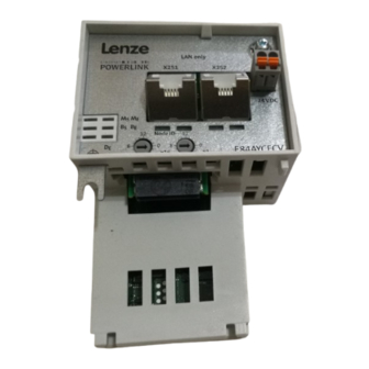
Page 14: Connections And Interfaces
(node ID) Node address setting ( 37) E84YCEC001D 5 LED status displays for diagnostics Module status displays ( 53) Fieldbus status displays ( 54) [3-2] E84AYCEC communication module (POWERLINK) Lenze · E84AYCEC communication module (POWERLINK) · EDS84AYCEC EN 4.0 - 02/2019... -
Page 15: Technical Data
Hardware manual for Inverter Drives 8400 Here you can find the ambient conditions and data on the electromagnetic compatibility (EMC), which also apply to the communication module. Lenze · E84AYCEC communication module (POWERLINK) · EDS84AYCEC EN 4.0 - 02/2019... -
Page 16: Protective Insulation
• the components to be connected must be provided with the second isolating dis- tance. Note! The existing protective insulation in the Inverter Drives 8400 is implemented according to EN 61800-5-1. Lenze · E84AYCEC communication module (POWERLINK) · EDS84AYCEC EN 4.0 - 02/2019... - Page 17 X106 Motor PTC X1 System bus (CANopen) X3 Analog inputs/outputs X4 Digital outputs X5 Digital inputs X6 Diagnostics MCI Slot for the communication module MMI Slot for the memory module Lenze · E84AYCEC communication module (POWERLINK) · EDS84AYCEC EN 4.0 - 02/2019...
- Page 18 • The separate potential area of the mains terminal has a "reinforced insulation". • Result: The insulation between the X100 mains terminal and the bus terminal is a "reinforced insulation". Lenze · E84AYCEC communication module (POWERLINK) · EDS84AYCEC EN 4.0 - 02/2019...
-
Page 19: Powerlink Communication Data
• For some codes, the processing time may be longer (see software manu- al/»Engineer« online help for the Inverter Drive 8400). There are no interdependencies between parameter data and process data. Lenze · E84AYCEC communication module (POWERLINK) · EDS84AYCEC EN 4.0 - 02/2019... -
Page 20: Dimensions
_ _ _ _ _ _ _ _ _ _ _ _ _ _ _ _ _ _ _ _ _ _ _ _ _ _ _ _ _ _ _ _ _ _ _ _ _ _ _ _ _ _ _ _ _ _ _ _ _ _ _ _ _ _ _ _ _ _ _ _ _ _ _ _ Dimensions E84YCER001B [4-2] Dimensions Type Dimensions [mm] E84AYCEC Lenze · E84AYCEC communication module (POWERLINK) · EDS84AYCEC EN 4.0 - 02/2019... -
Page 21: Installation
• The communication module is defective. • Fieldbus communication is not possible or faulty. Protective measures • Before touching the module, be sure that you are free of electrostatic charge. Lenze · E84AYCEC communication module (POWERLINK) · EDS84AYCEC EN 4.0 - 02/2019... -
Page 22: Mechanical Installation
2. Loosen the securing screw for the communication module at the standard device (3). 3. Insert the communication module into the MCI slot of the standard device (4). 4. Tighten the securing screw again (5). Lenze · E84AYCEC communication module (POWERLINK) · EDS84AYCEC EN 4.0 - 02/2019... -
Page 23: Mounting For Standard Devices Of 0.55 Kw Or More
3. Loosen the securing screw for the communication module at the standard device (3). 4. Insert the communication module into the MCI slot of the standard device (4). 5. Tighten the securing screw again (5). Lenze · E84AYCEC communication module (POWERLINK) · EDS84AYCEC EN 4.0 - 02/2019... -
Page 24: Exchanging The Communication Module
2. Pull the communication module out of the MCI slot of the standard device (2). 3. Insert the new communication module into the MCI slot of the standard device (3). 4. Tighten the securing screw again (4). Lenze · E84AYCEC communication module (POWERLINK) · EDS84AYCEC EN 4.0 - 02/2019... -
Page 25: Electrical Installation
For this observe the following notes: 1. Remove the plastic sheath of the cable at a length of 2 cm. 2. Fasten the cable shield to the shield support of the standard device. Lenze · E84AYCEC communication module (POWERLINK) · EDS84AYCEC EN 4.0 - 02/2019... -
Page 26: Network Topology
Inside the segment only Ethernet hubs may be used as infrastructure elements. The hubs must meet the requirements on class II repeaters acc. to IEEE 802.3u. For this purpose Lenze offers the dual hub integrated into the communication module and the se- parate eight-fold hub, type E94AZCEH. - Page 27 _ _ _ _ _ _ _ _ _ _ _ _ _ _ _ _ _ _ _ _ _ _ _ _ _ _ _ _ _ _ _ _ _ _ _ _ _ _ _ _ _ _ _ _ _ _ _ _ _ _ _ _ _ _ _ _ _ _ _ _ _ _ _ _ 3. Connect CN groups to the managing node via one external hub each. • For more than 2 CN groups, use an external 8-port hub (e.g. Lenze hub E94AZCEH). • For max. 7 CN groups one hub is sufficient.
-
Page 28: Ethernet Powerlink
Only asynchronous frames that are not addressed to nodes in the EPL network segment are for- warded. Tip! Detailed information on the function and setting of the router or gateway can be found in the documentation of the component manufacturer. Lenze · E84AYCEC communication module (POWERLINK) · EDS84AYCEC EN 4.0 - 02/2019... -
Page 29: Basic Ethernet Mode
( 37) 2. No operation with real-time EPL must be carried out. 3. No integration of a managing node (EPL address = 240) into the standard Ethernet network. Lenze · E84AYCEC communication module (POWERLINK) · EDS84AYCEC EN 4.0 - 02/2019... -
Page 30: Powerlink Connection
(AIDA). Note! To prevent the RJ45 socket from being damaged, insert or remove the Ethernet cable connector straight (at a right angle) into or from the socket. Lenze · E84AYCEC communication module (POWERLINK) · EDS84AYCEC EN 4.0 - 02/2019... - Page 31 RJ45 interfaces so that a connection can be established irrespective of the pola- rity of the opposite POWERLINK interface and irrespective of the type of cable used (standard patch cable or crossover cable). Lenze · E84AYCEC communication module (POWERLINK) · EDS84AYCEC EN 4.0 - 02/2019...
-
Page 32: Ethernet Cable Specification
B Braid C Foil shielding Twisted core pairs 1 ... 4 Colour code of the Ethernet cable ( 33) E94YCEP016 [5-7] Structure of the Ethernet cable (S/FTP, CAT 5e) Lenze · E84AYCEC communication module (POWERLINK) · EDS84AYCEC EN 4.0 - 02/2019... - Page 33 Rx + White / Orange White / Green blue blue White / Blue Blue / White Rx - orange green White / Brown White / Brown brown brown Lenze · E84AYCEC communication module (POWERLINK) · EDS84AYCEC EN 4.0 - 02/2019...
-
Page 34: External Voltage Supply
Description U = 24 V DC (20.4 V - 0 % ... 28.8 V + 0 %) I = 140 mA Reference potential for the external voltage supply Lenze · E84AYCEC communication module (POWERLINK) · EDS84AYCEC EN 4.0 - 02/2019... - Page 35 With wire end ferrule, without plastic sleeve 0.2 ... 1.5 mm (AWG 24 ... 16) With wire end ferrule, with plastic sleeve 0.2 ... 1.5 mm (AWG 24 ... 16) Stripping length 10 mm Lenze · E84AYCEC communication module (POWERLINK) · EDS84AYCEC EN 4.0 - 02/2019...
-
Page 36: Commissioning
Commissioning During commissioning, system-related data such as motor parameters, operating parameters, re- sponses, and parameters for fieldbus communication are defined for the inverter. For Lenze devices, this is done via the codes. The codes of the inverter and communication are saved non-volatilely as a data set in the memory module. -
Page 37: Node Address Setting
• Valid addresses for the communication module in the EPL network: • 1 … 100: Controlled node with Lenze module E94AYCEP as managing node • 1 … 239: Controlled node with managing node of another manufacturer • The corresponding Ethernet IP address of the communication module results from the address setting of the rotary coding switches: •... - Page 38 Internal check of the rotary coding switch setting after the system start Example: Setting of the node address "52" Position of the rotary coding switches Resulting node address × × × × 16) + (4 1) = 52 Lenze · E84AYCEC communication module (POWERLINK) · EDS84AYCEC EN 4.0 - 02/2019...
-
Page 39: Setting And Displays In The "Engineer
_ _ _ _ _ _ _ _ _ _ _ _ _ _ _ _ _ _ _ _ _ _ _ _ _ _ _ _ _ _ _ _ _ _ _ _ _ _ _ _ _ _ _ _ _ _ _ _ _ _ _ _ _ _ _ _ _ _ _ _ _ _ _ _ Setting and displays in the »Engineer« IP address (C13000) and the MAC address (C13004) are displayed on the Settings tab. Lenze · E84AYCEC communication module (POWERLINK) · EDS84AYCEC EN 4.0 - 02/2019... -
Page 40: Initial Switch-On
After a fault (e.g. short-term mains failure), it is sometimes undesirable or even imper- missible for the drive to restart. The restart protection is activated in the Lenze setting of the Inverter Drives 8400. The restart behaviour of the inverter can be set via C00142 ("auto-start option"): •... - Page 41 Fieldbus status displays ( 54) X251 green LED is lit if a connection to the node has been established. Status displays at the RJ45 sockets (X251, X252) ( 55) X252 green Lenze · E84AYCEC communication module (POWERLINK) · EDS84AYCEC EN 4.0 - 02/2019...
-
Page 42: Drive Synchronisation
• It is not necessary to adjust the sync window C01123 and the sync correction width C01124. Software manual/»Engineer« online help for the Inverter Drive 8400 Here you can find detailed information on drive synchronisation and the corresponding parameters. Lenze · E84AYCEC communication module (POWERLINK) · EDS84AYCEC EN 4.0 - 02/2019... -
Page 43: Optimisation Of Networks
, the value of the ( 29) 0x1F99 object (NMT_CNBasicEthernetTimeout_U32) must be higher than the value of the 0x1F89 object (NMT_BootTime_REC) which is the case by default. Index table ( 82) Lenze · E84AYCEC communication module (POWERLINK) · EDS84AYCEC EN 4.0 - 02/2019... -
Page 44: Process Data Transfer
• Up to 16 process data words (16 bit/word) can be exchanged per direction. • Process data are not saved in the inverter. • Process data are e.g. setpoints, actual values, control words, and status words. Lenze · E84AYCEC communication module (POWERLINK) · EDS84AYCEC EN 4.0 - 02/2019... -
Page 45: Access To Process Data / Pdo Mapping
Software manual / »Engineer« online help for the Inverter Drive 8400 Here you can find detailed information on the port/function block interconnection in the »Engineer« and on the port blocks. Lenze · E84AYCEC communication module (POWERLINK) · EDS84AYCEC EN 4.0 - 02/2019... -
Page 46: Preconfigured Port Interconnection Of The Process Data Objects (Pdo)
The preconfigured port interconnection of the process data objects can be activated by setting stan- dard device code C00007 = "40: MCI". The function block editor (FB Editor) serves to display the LP_MciIn and LP_MciOut port blocks with the preconfigured interconnections: Lenze · E84AYCEC communication module (POWERLINK) · EDS84AYCEC EN 4.0 - 02/2019... -
Page 47: Freely Configuring The Port Interconnection Of The Process Data Objects (Pdo)
2. Select the port blocks MCI_IN or MCI_OUT on the Ports tab with a mouse-click and activate them with the Activate button (B). 3. Click the Change Variable ... button. Lenze · E84AYCEC communication module (POWERLINK) · EDS84AYCEC EN 4.0 - 02/2019... - Page 48 Assignment Signal --> Function Block dialog window. Select the signals and then confirm the selection with OK. Lenze · E84AYCEC communication module (POWERLINK) · EDS84AYCEC EN 4.0 - 02/2019...
- Page 49 Furthermore you can assign signals to the individual control and status bits of the WORD_1 ... WORD_4 process data words via the buttons. Select signals and confirm the selection by clicking the OK button. Lenze · E84AYCEC communication module (POWERLINK) · EDS84AYCEC EN 4.0 - 02/2019...
- Page 50 FB Editor. Here you can also assign signals to the process data words. In order to improve the clarity, unassigned signals can be hidden for each block. Lenze · E84AYCEC communication module (POWERLINK) · EDS84AYCEC EN 4.0 - 02/2019...
-
Page 51: Monitoring
By default, there is no response in the controlled node. 2. To cause a response by the controlled node, you additionally have to ... • set a response of the controlled node (C13880/1). Lenze · E84AYCEC communication module (POWERLINK) · EDS84AYCEC EN 4.0 - 02/2019... -
Page 52: Diagnostics
The following status displays are distinguished: • Module status displays ( 53) • Fieldbus status displays ( 54) • Status displays at the RJ45 sockets (X251, X252) ( 55) Lenze · E84AYCEC communication module (POWERLINK) · EDS84AYCEC EN 4.0 - 02/2019... -
Page 53: Module Status Displays
An error has occurred in the communication module. A fieldbus error has occurred. The communication module is not accepted by the standard device. See notes given in the documentation for the standard device. Lenze · E84AYCEC communication module (POWERLINK) · EDS84AYCEC EN 4.0 - 02/2019... -
Page 54: Fieldbus Status Displays
29). EPL status: NMT_CS_BASIC_ETHERNET blinking EPL node is in the "Stopped" status (waiting for disconnection). EPL status: NMT_CS_STOPPED EPL node is in the operating phase. EPL status: NMT_CS_OPERATIONAL Lenze · E84AYCEC communication module (POWERLINK) · EDS84AYCEC EN 4.0 - 02/2019... -
Page 55: Status Displays At The Rj45 Sockets (X251, X252)
The LEDs at the RJ45 sockets X251 and X252 indicate the POWERLINK connection status. E84YCER005 Colour Status Description green No POWERLINK connection POWERLINK connection has been established. Flickers 50 ms Data communication of POWERLINK connection is active. POWERLINK collision has occurred. Lenze · E84AYCEC communication module (POWERLINK) · EDS84AYCEC EN 4.0 - 02/2019... -
Page 56: Troubleshooting With Module Signalling
Go back to point 1. combination. Please exchange. again. Go back to point 1. Please exchange. Go back to point 1. E94YCEP051 [9-1] Diagnostics - standard device / POWERLINK module Lenze · E84AYCEC communication module (POWERLINK) · EDS84AYCEC EN 4.0 - 02/2019... - Page 57 Diagnostics - network wiring Note! The BS (Bus State) LED refers to the Lenze communication module E94AYCEP as mana- ging node. This status display applies analogously to the managing nodes of other manufacturers. Lenze · E84AYCEC communication module (POWERLINK) · EDS84AYCEC EN 4.0 - 02/2019...
- Page 58 Diagnostics - POWERLINK operation Note! The LEDs ME (Module Error), BE (Bus Error) and BS (Bus State) refer to the Lenze commu- nication module E94AYCEP as managing node. These status displays apply analogously to the managing nodes of other manufacturers.
-
Page 59: Diagnostic Data
ID according to module 21 ... 24 Submodule number ID according to module 25, 26 Alarm specification 0xB000 27, 28 User structure ID 0x0001 29 ... 32 Error code Lenze · E84AYCEC communication module (POWERLINK) · EDS84AYCEC EN 4.0 - 02/2019... - Page 60 • 6: Information Error subject area 0x01bc (444 Error ID 0x8131 (33073 Software manual/»Engineer« online help for Inverter Drive 8400 Detailed information on the error codes is provided here. Lenze · E84AYCEC communication module (POWERLINK) · EDS84AYCEC EN 4.0 - 02/2019...
-
Page 61: Error Messages
0x01bc8261 33377 EPL: Invalid address selected 1: No Response 0x01bc8265 33381 EPL: Synchronisation of MN lost 0: None C13880/2 0x01bc8266 33382 EPL: Frame error (CRC) 0: None C13880/3 Lenze · E84AYCEC communication module (POWERLINK) · EDS84AYCEC EN 4.0 - 02/2019... -
Page 62: Possible Causes And Remedies
No reaction System fault Fault Trouble Quick stop by trouble WarningLocked Warning Information Cause Remedy Communication module is defective. Send the communication module and a description of the fault to Lenze. Lenze · E84AYCEC communication module (POWERLINK) · EDS84AYCEC EN 4.0 - 02/2019... - Page 63 No reaction System fault Fault Trouble Quick stop by trouble WarningLocked Warning Information Cause Remedy Access to parameter set in memory module via standard Download application again (including module). device was not successful. Lenze · E84AYCEC communication module (POWERLINK) · EDS84AYCEC EN 4.0 - 02/2019...
- Page 64 • A device in the network is not EPL-compliant. • Reduce EMC interference on the network or use an additional shield connection. • EMC interference is too strong. Lenze · E84AYCEC communication module (POWERLINK) · EDS84AYCEC EN 4.0 - 02/2019...
-
Page 65: Parameter Reference
Here you will find general information on parameters. [Search-Keywords] Hlp_Para 11.1 Parameters of the communication module This chapter lists the parameters of the E84AYCEC communication module (POWERLINK) in nume- rically ascending order. C13000 Parameter | Name: Data type: UNSIGNED_32 C13000 | 0x1E40.2 IP Address... - Page 66 • 00-0A-86 = Lenze • xx-yy-zz = consecutive number Read access Write access CINH PLC-STOP No transfer PDO_MAP_RX PDO_MAP_TX COM MOT Lenze · E84AYCEC communication module (POWERLINK) · EDS84AYCEC EN 4.0 - 02/2019...
- Page 67 The managing node does not send any PRes frames The managing node sends PRes frames 13 ... 30 Reserved / No function 31 (MSB) Bits 0 ... 30 inhibited Bits 0 ... 30 enabled Lenze · E84AYCEC communication module (POWERLINK) · EDS84AYCEC EN 4.0 - 02/2019...
- Page 68 The managing node does not send any PRes frames The managing node sends PRes frames 13 ... 30 Reserved / No function 31 (MSB) Bits 0 ... 30 inhibited Bits 0 ... 30 enabled Lenze · E84AYCEC communication module (POWERLINK) · EDS84AYCEC EN 4.0 - 02/2019...
- Page 69 No "POWERLINK to fieldbus" router function. The device can be used as an "POWERLINK to fieldbus" router (router type 1). 14 ... 31 Reserved / No function (MSB) Lenze · E84AYCEC communication module (POWERLINK) · EDS84AYCEC EN 4.0 - 02/2019...
- Page 70 17000 17000 18000 18000 19000 19000 20000 20000 Read access Write access CINH PLC-STOP No transfer PDO_MAP_RX PDO_MAP_TX COM MOT Lenze · E84AYCEC communication module (POWERLINK) · EDS84AYCEC EN 4.0 - 02/2019...
- Page 71 (min. value | unit | max. value) Byte 1490 36 bytes Read access Write access CINH PLC-STOP No transfer PDO_MAP_RX PDO_MAP_TX COM MOT Lenze · E84AYCEC communication module (POWERLINK) · EDS84AYCEC EN 4.0 - 02/2019...
- Page 72 (min. value | unit | max. value) μs 4294967295 5000000 μs Read access Write access CINH PLC-STOP No transfer PDO_MAP_RX PDO_MAP_TX COM MOT Lenze · E84AYCEC communication module (POWERLINK) · EDS84AYCEC EN 4.0 - 02/2019...
- Page 73 Info C13079/1 0 cycles C13079/100 0 cycles Read access Write access CINH PLC-STOP No transfer PDO_MAP_RX PDO_MAP_TX COM MOT Lenze · E84AYCEC communication module (POWERLINK) · EDS84AYCEC EN 4.0 - 02/2019...
- Page 74 Info C13853/1 wState C13853/2 wOut2 C13853/16 wOut16 Read access Write access CINH PLC-STOP No transfer PDO_MAP_RX PDO_MAP_TX COM MOT Lenze · E84AYCEC communication module (POWERLINK) · EDS84AYCEC EN 4.0 - 02/2019...
- Page 75 NMT_CS_OPERATIONAL 77 Stopped NMT_CS_STOPPED 30 BasicEthernet NMT_CS_BASIC_ETHERNET Read access Write access CINH PLC-STOP No transfer PDO_MAP_RX PDO_MAP_TX COM MOT Lenze · E84AYCEC communication module (POWERLINK) · EDS84AYCEC EN 4.0 - 02/2019...
- Page 76 0: No Response Error reaction at CRC error Read access Write access CINH PLC-STOP No transfer PDO_MAP_RX PDO_MAP_TX COM MOT Lenze · E84AYCEC communication module (POWERLINK) · EDS84AYCEC EN 4.0 - 02/2019...
- Page 77 Bit 5 Information Bit 6 Reserved Bit 7 Reserved Read access Write access CINH PLC-STOP No transfer PDO_MAP_RX PDO_MAP_TX COM MOT Lenze · E84AYCEC communication module (POWERLINK) · EDS84AYCEC EN 4.0 - 02/2019...
- Page 78 Display of the version number of the communication module firmware Read access Write access CINH PLC-STOP No transfer PDO_MAP_RX PDO_MAP_TX COM MOT Lenze · E84AYCEC communication module (POWERLINK) · EDS84AYCEC EN 4.0 - 02/2019...
- Page 79 (min. value | unit | max. value) Read access Write access CINH PLC-STOP No transfer PDO_MAP_RX PDO_MAP_TX COM MOT Lenze · E84AYCEC communication module (POWERLINK) · EDS84AYCEC EN 4.0 - 02/2019...
-
Page 80: Table Of Attributes
1000 ≡ 3 decimal positions Access Read access Reading permitted Write access Writing permitted CINH Controller inhibit (CINH) required Writing is only possible when the controller is inhibited (CINH) Lenze · E84AYCEC communication module (POWERLINK) · EDS84AYCEC EN 4.0 - 02/2019... - Page 81 10673 29B1 VISIBLE_STRING C13910 Last Module Error 10665 29A9 UNSIGNED_32 C13915 CustomerObject[16] 10660 29A4 OCTET_STRING C13920 Current address switch 10655 299F UNSIGNED_8 Lenze · E84AYCEC communication module (POWERLINK) · EDS84AYCEC EN 4.0 - 02/2019...
-
Page 82: Index Table
Version of PDO mapping 0x1404.0 PDO_RxCommParam_04h_REC NumberOfEntries 0x1404.1 PDO_RxCommParam_04h_REC NodeID_U8 0x1404.2 PDO_RxCommParam_04h_REC MappingVersion_U8 Version of PDO mapping 0x1405.0 PDO_RxCommParam_05h_REC NumberOfEntries 0x1405.1 PDO_RxCommParam_05h_REC NodeID_U8 0x1405.2 PDO_RxCommParam_05h_REC MappingVersion_U8 Version of PDO mapping Lenze · E84AYCEC communication module (POWERLINK) · EDS84AYCEC EN 4.0 - 02/2019... - Page 83 Limits the range with regard to router stations passed. 0x1E4A.3 NWL_IpGroup_REC ForwardingDatagrams_ Counter for routed frames 0x1F81.0 NMT_NodeAssignment_AU32 NumberOfEntries 0x1F81.1 NMT_NodeAssignment_AU32 NodeAssignment C13028/1...100 ...100 0x1F81.240 NMT_NodeAssignment_AU32 NodeAssignment C13029/1 0x1F81.253 NMT_NodeAssignment_AU32 NodeAssignment C13029/2 Lenze · E84AYCEC communication module (POWERLINK) · EDS84AYCEC EN 4.0 - 02/2019...
- Page 84 NMT_CycleTiming_REC AsyncMTUSize_U16 C13075 0x1F98.9 NMT_CycleTiming_REC Prescaler_U16 C13076 0x1F99 NMT_CNBasicEthernetTimeout C13078 _U32 0x1F9A NMT_HostName_VSTR VS32 C13898 0x1F9B.1 NMT_MultiplCycleAssign_AU8 CycleNo C13079 0 ... value of ...100 0x1F98.7 0x1F9E NMT_ResetCmd_U8 C13102 Lenze · E84AYCEC communication module (POWERLINK) · EDS84AYCEC EN 4.0 - 02/2019...
-
Page 85: Index
Current address switch (C13920) C13029 | 0x1F81 Node Assignment CustomerObject (C13915) C13040 | 0x1F82 Feature Flags Cycle time C13060 | 0x1006 Cycle Time C13066 | 0x1F8D PResPayloadLimit RPDO CN Lenze · E84AYCEC communication module (POWERLINK) · EDS84AYCEC EN 4.0 - 02/2019... - Page 86 Mounting for standard devices of 0.55 kW or more 0x01bc6430 0x01bc8131 0x01bc8261 Nameplate 0x01bc8265 Network topology 0x01bc8266 Node address setting Error reaction on RPDO check (C13885) Node addresses (node IDs) Error response (C13880) Lenze · E84AYCEC communication module (POWERLINK) · EDS84AYCEC EN 4.0 - 02/2019...
- Page 87 Status displays (LEDs) Status displays at the RJ45 sockets (X251, X252) Structure of the Ethernet cable Suppress emergency message upon (C13887) Synchronisation System error messages Table of attributes Target group Lenze · E84AYCEC communication module (POWERLINK) · EDS84AYCEC EN 4.0 - 02/2019...
- Page 88 _ _ _ _ _ _ _ _ _ _ _ _ _ _ _ _ _ _ _ _ _ _ _ _ _ _ _ _ _ _ _ _ _ _ _ _ _ _ _ _ _ _ _ _ _ _ _ _ _ _ _ _ _ _ _ _ _ _ _ _ _ _ _ _ Lenze · E84AYCEC communication module (POWERLINK) · EDS84AYCEC EN 4.0 - 02/2019...
- Page 89 Perhaps we have not succeeded in achieving this objective in every respect. If you have suggestions for improvement, please e-mail us feedback-docu@lenze.com Thank you very much for your support. Your Lenze documentation team...
- Page 90 E84AYCEC communication module (POWERLINK) · 13564917 · EDS84AYCEC · EN 4.0 · 02/2019 · TD23 Lenze Drives GmbH Postfach 10 13 52, D-31763 Hameln Breslauer Straße 3, D-32699 Extertal Germany HR Lemgo B 6478 +49 5154 82-0 +49 5154 82-2800 sales.de@lenze.com...
Need help?
Do you have a question about the E84AYCEC and is the answer not in the manual?
Questions and answers