
Related Manuals for wtw NitraLyt 700 IQ


Summary of Contents for wtw NitraLyt 700 IQ
- Page 1 Operating manual NitraLyt 700 IQ IQ S nitrate sensor ENSOR ba75397e03 12/2004...
- Page 2 The latest version of the present operating manual can be found on the Internet under www.WTW.com. © Copyright Weilheim 2004, WTW GmbH Reprinting - even as excerpts - is only allowed with the explicit written authorization of WTW GmbH, Weilheim. Printed in Germany. ba75397e03 12/2004...
-
Page 3: Table Of Contents
NitraLyt 700 IQ List of contents Overview ........2-1 How to use this component operating manual . - Page 4 List of contents NitraLyt 700 IQ Measurement conditions ......9-1 Characteristic data on delivery ....9-2 Indexes .
-
Page 5: Overview
® NitraLyt 700 IQ Overview Overview How to use this component operating manual Structure of the operating IQ S ENSOR manual Fig. 1-1 Structure of the IQ S operating manual ENSOR operating manual has a modular structure like the IQ S ENSOR . -
Page 6: Structure Of The Nitralyt ® 700 Iq Nitrate Sensor
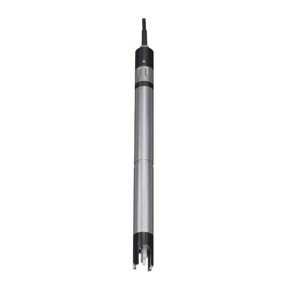
® Overview NitraLyt 700 IQ ® Structure of the NitraLyt 700 IQ nitrate sensor ® Fig. 1-2 Structure of the NitraLyt 700 IQ nitrate sensor Protective hood Temperature probe NitraLyt combination electrode ® with NitraLyt NHA reference electrode ® and NitraLyt NHA/AT exchange electrode (combination electrode not contained in the scope of delivery). -
Page 7: Safety
® NitraLyt 700 IQ Safety Safety This component operating manual contains special instructions that ® must be followed in the operation of the NitraLyt 700 IQ nitrate sen- sor. Thus, it is essential to read this component operating manual before carrying out any work using this sensor. In addition to this man- ual, the S chapter of the IQ S system operating man-... -
Page 8: Authorized Use
) must be main- ECHNICAL DATA tained during the operation and transport of the sensor. Protect the sensor, particularly against frost or overheating. Caution The sensor may only be opened by specialists authorized by WTW. 2 - 2 ba75397d03 12/2004... - Page 9 ® NitraLyt 700 IQ Safety Safe operation If safe operation is no longer possible, the sensor must be taken out of operation and secured against inadvertent operation. Safe operation is no longer possible if the sensor: ! has been damaged in transport ! has been stored under adverse conditions for a lengthy period of time ! is visibly damaged...
- Page 10 ® Safety NitraLyt 700 IQ 2 - 4 ba75397d03 12/2004...
-
Page 11: Commissioning
Do not suspend the sensor on the sensor connection cable. Use an armature or electrode holder. Information on this and other IQ S ENSOR accessories is given in the WTW catalog and in the Internet. ba75397d03 12/2004 3 - 1... - Page 12 ® Commissioning NitraLyt 700 IQ Connecting the sensor Take the protective caps off the plug connections of the sensor to the sensor and the SACIQ sensor connection cable, and keep them safe. connection cable Plug the jack of the SACIQ sensor connection cable onto the plug head connector of the sensor.
-
Page 13: Commissioning / Getting The Sensor Ready For Measuring
® NitraLyt 700 IQ Commissioning Commissioning / Getting the sensor ready for measuring Mounting the Unscrew the protective hood from the sensor. combination electrode Pull off the blind plug from the plug head socket of the sensor. Prepare the combination electrode to be mounted in the sen- sor. - Page 14 ® Commissioning NitraLyt 700 IQ ® Grease the two sealing rings (1) of the NitraLyt electrode using the grease from the tube supplied. Screw the reference electrode into the plug head socket of the sensor. Push the unit into the sensor up to the stop. 3 - 4 ba75397d03 12/2004...
- Page 15 ® NitraLyt 700 IQ Commissioning Caution Push the electrode into the sensor right up to the stop so that the con- nection is watertight. Leaks could lead to the destruction of the sensor. Screw the protective hood onto the sensor. Carry out the settings for the sensor on the terminal of the mea- suring system (see section 3.4).
-
Page 16: Carrying Out The Settings For The Sensor On The Terminal Of The Iq Sensor Net System
® Commissioning NitraLyt 700 IQ Carrying out the settings for the sensor on the termi- nal of the IQ S system ENSOR The following settings can be carried out for the sensor: Menu item Possible settings Explanations ! NO3 Measuring mode The citation form of the mass concentra- tion or the voltage of the electrode. - Page 17 The concentration of the test sample determined in a reference procedure must be entered. ! 2-point calibration using any two WTW ! 2 point stand. (3) standard solutions. The concentration of the standard solutions must be entered.
- Page 18 ® Commissioning NitraLyt 700 IQ Menu item Possible settings Explanations Temp. adjustment -1.5 °C ... +1.5 °C The temperature compensation function enables the temperature sensor to be bal- anced against a reference temperature measurement (displacement of the zero point by ±1.5 °C). Notes: ! Due to the thermal capacity of the sen- sor, it is necessary to place it in a con-...
- Page 19 ® NitraLyt 700 IQ Commissioning Fig. 3-2 140 - Settings of sensors and diff. sensors Confirm the selection with The settings of the sensor are displayed. Fig. 3-3 140 - Settings of sensors and diff. sensors Make the sensor settings with and confirm each of them with Select the Save and quit menu item with...
- Page 20 ® Commissioning NitraLyt 700 IQ 3 - 10 ba75397d03 12/2004...
-
Page 21: Calibration And Measuring
® NitraLyt 700 IQ Calibration and measuring Calibration and measuring Calibration 4.1.1 General information Why calibrate? When a nitrate electrode is operated its characteristic curve changes with the course of time. The characteristic curve is generally character- ized by the slope and the axis intercept. The characteristic curve is the base for calculating the measured value from the electrode voltage. -
Page 22: Overview Of The Calibration Procedures
® Calibration and measuring NitraLyt 700 IQ 4.1.2 Overview of the calibration procedures ® For nitrate measurements with the NitraLyt 700 IQ sensor, the follow- ing calibration procedures can be selected: 1 point standard (1) 1-point calibration in a standard solution. 1 point ref. -
Page 23: Calibrating In Practice
® NitraLyt 700 IQ Calibration and measuring 4.1.3 Calibrating in practice Initial calibration The first calibration (initial calibration) is especially important as it is the reference point for all other calibrations (following calibrations). An initial calibration is required each time an electrode is commis- sioned. - Page 24 ® Calibration and measuring NitraLyt 700 IQ Optimum calibration of an electrode New electrode installed Change setting Sensor settings: manually Initial calibration On Important: Drift potential Calibration with 2 point standard (3) and slope are determined Setting is changed Sensor settings: automatically Initial calibration Off Matrix effects of...
-
Page 25: General Course Of A Calibration
® NitraLyt 700 IQ Calibration and measuring 4.1.4 General course of a calibration Preparatory activities An optimum calibration result is possible if you, ! before calibrating, – condition the sensor in the ES/NO3_ISA-50 standard solution with 50 mg/l NO3-N for approx. 10 min –... - Page 26 ® Calibration and measuring NitraLyt 700 IQ Fig. 4-3 200 - Calibrate sensor Confirm with The following display (or similar, depending on the selected calibration procedure) appears: Fig. 4-4 200 - Calibrate sensor The further course depends on the respective calibration pro- cedure.
- Page 27 ® NitraLyt 700 IQ Calibration and measuring Note You can break off the calibration procedure at any time with the key. The system continues to work with the old calibration data. How- ever, you have to switch off the maintenance condition in any case. Note The sensor determines a stable measured value with each measure- ment during the course of a calibration.
-
Page 28: Calibration Procedure, 1 Point Standard (1)
® Calibration and measuring NitraLyt 700 IQ 4.1.5 Calibration procedure, 1 point standard (1) General information The 1 point standard (1) 1-point calibration is carried out using one standard solution. The procedure includes a conditioning process. The conditioning takes 15 min and is important so the temperatures of stan- dard solution and electrode can adjust to each other and a stable con- centration can be reached at the electrode membrane. - Page 29 ® NitraLyt 700 IQ Calibration and measuring Discard used standard. Immerse Immerse the sensor in fresh stan- sensor in new standard with simi- dard solution of similar concen- lar concentration. tration as described. Start calibration. After completing the operating steps confirm with The measurement is started.
-
Page 30: Calibration Procedure, 1 Point Ref. (2)
® Calibration and measuring NitraLyt 700 IQ 4.1.6 Calibration procedure, 1 point ref. (2) The 1 point ref. (2) 1-point calibration is carried out with the sample and in two main steps, each of which is started with c. Note Determine the calibration value and take the sample from the aeration tank after the aeration phase is finished. - Page 31 ® NitraLyt 700 IQ Calibration and measuring Sampling and You have to be in the measured value display to continue the calibra- determining the tion. reference concentration Continue with sampling and determining the reference concentration as follows. Take a sample. Note The nitrate content has to be determined immediately after taking the sample as the nitrate content changes very quickly due to the micro...
- Page 32 ® Calibration and measuring NitraLyt 700 IQ Citation form of ref. conc. Confirm with NO3 (0.5..450.0 mg/l) Select the citation form with NO3 (5..4500 mg/l) Confirm with NO3-N (0.1..100.0 mg/l) Confirm with NO3-N (1..1000 mg/l) Input reference concentration Confirm with Value determined Value of ref.
-
Page 33: Calibration Procedure, 2 Point Stand. (3)
® NitraLyt 700 IQ Calibration and measuring 4.1.7 Calibration procedure, 2 point stand. (3) General information The 2 point stand. (3) two-point calibration is carried out with two stan- dard solutions of different concentrations. The procedure includes two conditioning processes. Each conditioning process takes 15 min and is important so the temperatures of standard solution and electrode can adjust to each other and a stable concentration can be reached at the electrode membrane. - Page 34 ® Calibration and measuring NitraLyt 700 IQ Displays Explanation Cal.: 2 POINT STANDARD (3) Confirm with Calibration values for stand. with higher concentration determined. Have stand. with lower concentra- tion ready Rinse sensor with stand. with Confirm with lower concentration. Immerse sensor in stand.
-
Page 35: Calibration Procedure, Simple Std. Add. (4)
® NitraLyt 700 IQ Calibration and measuring 4.1.8 Calibration procedure, Simple std. add. (4) Calibration with simple standard addition is carried out in the sample while adding standard. The volumes of test sample and standard have to be exactly dosed. The following appliances are suitable for dosing: ! Measuring cylinder to determine the volume of the sample ! Pipette (microliter pipette as necessary) for accurate dosing of the... - Page 36 ® Calibration and measuring NitraLyt 700 IQ is the volume ratio between the test sample and standard to be added. If several combinations for concentration/volume ratio (bars) are possible for the determination, select the bar where the expected NO3-N concentration is more in the center. Example: The expected average concentration is approx.
- Page 37 ® NitraLyt 700 IQ Calibration and measuring Note Make sure the citation form is correct for all specifications of the con- centration. Operating steps during Display Explanation calibration Cal.: SIMPLE STD. ADD. (4) Confirm with Have test sample ready for cali- bration Input sample volume Confirm with...
-
Page 38: Calibration Procedure, Double Std. Add. (5)
® Calibration and measuring NitraLyt 700 IQ Display Explanation Calibration successful The values for Conc. (NO3-N), Conc. (NO3-N) x mg/l Slope and Drift voltage are dis- Slope y mV* played. Drift voltage z mV Calibration is complete. Confirm End of SIMPLE STD ADD (4) cal. with The display returns to the mea- sured value display. - Page 39 ® NitraLyt 700 IQ Calibration and measuring Note Make sure the citation form is correct for all specifications of the con- centration. Operating steps during Display Explanation calibration Cal.: DOUBLE STD. ADD. (5) Confirm with Have test sample ready for cali- bration Input sample volume Confirm with...
-
Page 40: Calibration Result
® Calibration and measuring NitraLyt 700 IQ Display Explanation Add standard to sample Confirm with * Wait for a stable measured Confirm with value. The measurement begins. Cal.: DOUBLE STD. ADD. (5) Confirm with Reference voltage determined after first standard addition Add standard to sample Confirm with * Wait for a stable measured... - Page 41 ® NitraLyt 700 IQ Calibration and measuring A calibration can have the following results: Possible results of the Display after the Log book entries calibration calibration (meaning/actions) Measured value display Sensor was successfully calibrated. Slope and drift potential are within the valid range.
- Page 42 ® Calibration and measuring NitraLyt 700 IQ Calibration history Calibration data of the initial calibra- tion. List with calibration data of the last cali- brations Fig. 4-6 330 - Calibration history of selected sensor The calibration history contains the following information: Date Date of the calibration S(*)
-
Page 43: Measuring
® NitraLyt 700 IQ Calibration and measuring Measuring Submerse the sensor with the mounted combination electrode in the sample. Read the measured value on the terminal of the IQ S ENSOR system. Note Please pay attention to: ! the minimum immersion depth of the sensor (> 70 mm) ! the measuring range of the electrode used (see operating manual of the electrode). -
Page 44: Further Influences On The Measured Value
Fig. 4-7 shows the interrelationship of the real and displayed NO3-N value for different chloride contents. The characteristic curve with optimum chloride compensation corresponds to the characteristic curve without chloride contents. c (NO3-N) [mg/l] angezeigt von NitraLyt 700 IQ 1000 1000 0 mg/l Cl c (NO3-N) [mg/l]... -
Page 45: Maintenance And Changing The Electrode
® NitraLyt 700 IQ Maintenance and changing the electrode Maintenance and changing the electrode ® The NitraLyt 700 IQ nitrate sensor is maintenance-free. Warning Contact with the sample can be dangerous for the user! Depending on the type of sample, suitable protective measures must be taken (pro- tective clothing, protective goggles, etc.). - Page 46 ® Maintenance and changing the electrode NitraLyt 700 IQ Replacing the electrode If it is necessary to replace an electrode, proceed as follows: Unscrew the protective hood from the sensor. Use the protective hood as a tool to lever out the electrode. Carefully pull out the electrode until the plug head screwed fit- ting can be seen.
- Page 47 ® NitraLyt 700 IQ Maintenance and changing the electrode Screw in a new electrode. Push the unit into the sensor up to the stop. Screw the protective hood onto the sensor. ba75397d03 12/2004 5 - 3...
-
Page 48: Disposal
® Maintenance and changing the electrode NitraLyt 700 IQ Calibrate the sensor and the electrode with the measuring sys- tem (see section 4.1). Disposal Sensor We recommend disposing of the sensor as electronic refuse. Electrodes If no official regulations apply to the contrary, used and defective elec- trodes can be treated as household waste. -
Page 49: Replacement Parts And Accessories
® NitraLyt 700 IQ Replacement parts and accessories Replacement parts and accessories Sensor and electrodes Nitrate sensor Model Order no. ® NitraLyt 700 IQ 107022 Nitrate electrodes Model Order no. ® Reference electrode NitraLyt 107024 ® Exchange electrode NitraLyt NHA/AT 107026 General accessories Protective hood... - Page 50 Replacement parts and accessories NitraLyt 700 IQ Cleaning system Model Order no. CH Cleaning Head 900107 MIQ/CHV Valve Module 900109 Note Information on other IQ S accessories is given in the WTW ENSOR catalog and in the Internet. 6 - 2 ba75397d03 12/2004...
-
Page 51: What To Do If
® NitraLyt 700 IQ What to do if... What to do if... No measured value Cause Remedy – Sensor not connected – Connect the sensor – Unknown – Look in the log book Measurement does not Cause Remedy function – Electrode not connected –... - Page 52 ® What to do if... NitraLyt 700 IQ Cause Remedy – Drift of the electrode too high – Replace the electrode 7 - 2 ba75397d03 12/2004...
-
Page 53: Technical Data
® NitraLyt 700 IQ Technical data Technical data General features Electrode that can be NitraLyt (The NitraLyt combination electrode consists of the ® ® integrated NitraLyt NHA reference electrode and the NitraLyt NHA/AT exchange electrode.) Temperature via integrated NTC measurement Range - 5 °C ... -
Page 54: Characteristic Data On Delivery
® Technical data NitraLyt 700 IQ Type of protection Sensor with installed combi- IP 68; 0.2 bar (2x10 nation electrode and includ- ing SACIQ sensor connection cable Sensor plug head connector IP 67 without sensor connection cable (sensor with installed combination electrode) Depth of immersion Min. - Page 55 ® NitraLyt 700 IQ Technical data Electrical data Nominal voltage Max. 24 VDC via the IQ S (for more ENSOR details, see T chapter ECHNICAL DATA of the IQ S system oper- ENSOR ating manual) Power consumption 0.2 W Protective class Instrument safety Applicable norms –...
- Page 56 ® Technical data NitraLyt 700 IQ 8 - 4 ba75397d03 12/2004...
-
Page 57: Indexes
® NitraLyt 700 IQ Indexes Indexes Explanation of the messages This chapter contains a list of all the message codes and related mes- sage texts that can occur in the log book of the IQ S system ENSOR ® for the NitraLyt 700 IQ sensor. -
Page 58: Info Messages
* Check installation and cable lengths, Follow installation instructions * Power unit(s) overloaded, add power unit(s) * Defective components, replace components ES1361 Component hardware defective * Contact WTW 9.1.2 Info messages Message code Message text IC1361 Sensor has been successfully calibrated... -
Page 59: Status Info
® NitraLyt 700 IQ Indexes Status info The status info is a piece of coded information about the current state of a sensor. Each sensor sends this status info to the controller. The status info a sensor consists of 32 bits, each of which can have the value 0 or 1. - Page 60 ® Indexes NitraLyt 700 IQ 9 - 4 ba75397d03 12/2004...
- Page 61 Wissenschaftlich-Technische Werkstätten GmbH Dr.-Karl-Slevogt-Straße 1 D-82362 Weilheim Germany Tel: +49 (0) 881 183-0 +49 (0) 881 183-100 Fax: +49 (0) 881 183-420 E-Mail: Info@WTW.com Internet: http://www.WTW.com...
Need help?
Do you have a question about the NitraLyt 700 IQ and is the answer not in the manual?
Questions and answers