Table of Contents
Advertisement
Advertisement
Table of Contents

Related Manuals for Aerohive AP120


Summary of Contents for Aerohive AP120
- Page 1 Aerohive Hardware Reference Guide...
- Page 3 Copyright © 2013 Aerohive Networks, Inc. All rights reserved. Aerohive Networks, the Aerohive Networks logo, HiveOS, HiveAP, and HiveManager are trademarks of Aerohive Networks, Inc. All other trademarks and registered trademarks are the property of their respective companies. Information in this document is subject to change without notice. No part of this document may be...
- Page 4 About This Guide This guide describes Aerohive hardware devices, including component descriptions, installation and mounting instructions, wiring diagrams, and hardware specifications for each device. This guide is a useful resource for all Aerohive administrators. Aerohive...
-
Page 5: Table Of Contents
Contents Chapter 1 AP110 and AP120 Platforms ............9 AP110 and AP120 Product Overview ..........10 Ethernet Port ................11 Reset Button ................11 Status Indicator................11 Antennas..................12 Mounting an AP110 or AP120............12 Ceiling Mount ................13 Locking the AP ................ 14 Surface Mount ................ - Page 6 Reset Button ................52 Status LEDs ................. 52 Antennas..................53 MIMO ..................53 Mounting the AP340 ..............54 Ceiling Mount ................54 Locking the AP340 ..............56 Plenum Mount................56 Suspended Mount................59 Surface Mount ................61 Device, Power, and Environmental Specifications ......62 Aerohive...
- Page 7 Chapter 6 AP330 and AP350 Platforms ............. 63 Product Overview..............64 Ethernet Ports ................65 Console Port ................65 Reset Button ................66 USB Modem Port ................66 Status Indicator................66 Antennas..................67 Mounting the AP330 or AP350............68 Ceiling Mount ................68 Surface Mount ................
- Page 8 Standard (non-PoE) Ethernet Port Pin Assignments........ 109 Power over Ethernet Port Pin Assignments ......... 110 Smart PoE ................111 Aggregate and Redundant Interfaces ..........112 Aggregate Interface..............112 Redundant Interface ..............113 RJ45 Console Port Pin Assignments ..........113 Aerohive...
- Page 9 DB9 Console Port Pin Assignments ..........114 Configuring Antennas .............. 115 Single-direction Antennas.............. 115 Omnidirectional Antennas ............. 116 MIMO .................. 116 Using MIMO with Legacy Clients ............118 Index ..................... 119 Hardware Reference Guide...
- Page 10 Contents Aerohive...
-
Page 11: Chapter 1 Ap110 And Ap120 Platforms
• "Device, Power, and Environmental Specifications" on page 16 AP110 and AP120 devices support the same 802.11n features as the AP320 and AP340 devices. Of particular interest is their support of 2x2 MIMO (Multiple Input, Multiple Output). For more information, see "MIMO"... -
Page 12: Ap110 And Ap120 Product Overview
The AP110 and AP120 are both multi-channel wireless access points. The AP110 contains a dual-band radio that can operate at either 2.4 GHz or 5 GHz—but not in both bands simultaneously. The AP120 contains a 2.4 GHz radio and a 5 GHz radio that can operate concurrently through four internal antennas. These devices support a variety of Wi-Fi security protocols, including WPA (Wi-Fi Protected Access) and WPA2. -
Page 13: Ethernet Port
Status Indicator The status indicator has been incorporated into the Aerohive logo on the top of the AP110 and AP120. It is illuminated by various colors to indicate different states of activity. The meanings of the colors are as follows: Dark •... -
Page 14: Antennas
On the AP110, the two dual-band antennas link to a dual-band radio, which can operate in the 2.4-GHz band for 802.11b/g/n or the 5-GHz band for 802.11a/n, but not in both bands simultaneously. On the AP120, the two 2.4-GHz antennas link to one radio, and the two 5-GHz antennas link to the other radio, both of which can operate concurrently. -
Page 15: Ceiling Mount
AP110 AP120 OUNTING AN Ceiling Mount To mount an AP to a track in a dropped ceiling, use the appropriate track clip for the width of the ceiling track. Two clips ship with the AP: one for 1" (2.54 cm) tracks and one for 1/2" (1.27 cm) tracks. -
Page 16: Locking The Ap
Chapter 1 AP110 and AP120 Platforms 4. Holding the AP upside down, raise it until the threaded stud on the track clip enters the hole on the AP. Then revolve the AP until it is firmly attached to the clip. See... -
Page 17: Surface Mount
Surface Mount You can attach an AP110 or AP120 to any flat surface that supports its weight. First, attach two screws to the surface. Then, make a hole in the wall a few inches or centimeters above the screws so that you can pass the cables through the wall to the AP. -
Page 18: Device, Power, And Environmental Specifications
NVIRONMENTAL PECIFICATIONS Understanding the specifications for the AP110 and AP120 devices is necessary for optimal deployment and device operation. The following specifications describe the physical features and hardware components, the power adapter and PoE (Power over Ethernet) electrical requirements, and the temperature and humidity ranges in which the device can operate. -
Page 19: Chapter 2 Ap121 And Ap141 Platforms
Chapter 2 AP121 and AP141 Platforms The AP121and AP141 wireless access points are designed for excellent throughput and range. They provide dual concurrent 802.11b/g/n and 802.11a/n radios for 2x2 MIMO (Multiple Input Multiple Output) antenna configurations. When you enable 802.11n high-throughput options such as wide-channel mode (40-MHz channels), A-MPDU and A-MSDU packet aggregation, short guard interval, and MCS15 data rates, they can provide a PHY data rate up to 300 Mbps per radio. -
Page 20: Ap121 And Ap141 Product Overview
A) connectors. The antennas and the connectors are labeled for easy identification. See "Antennas" on page Console port You can access the CLI by making a serial connection to the RJ45 console port. See "Console Port" on page Aerohive... -
Page 21: Ethernet Ports
The AP121 and AP141 devices have one RJ45 10/100/1000Base-T/TX Ethernet port (Eth0). The AP can receive power through an Ethernet connection to the ETH0 port from PSE (power sourcing equipment) that is compatible with the 802.3af standard. Aerohive provides suitable PoE (power over Ethernet) injectors as an optional accessory. -
Page 22: Console Port
Yellow (steady): This port has made a successful 10/100 Mbps link. • Yellow (flashing): This port is sending and receiving traffic at 10/100 Mbps. • Green (steady): This port has made a successful 1000 Mbps link. • Green (flashing): This port is sending and receiving traffic at 1000 Mbps. Aerohive... -
Page 23: Antennas
AP121 AP141 P RODUCT VERVIEW Antennas The antennas for the AP121 and AP141 are described below. AP121 The AP121 has four internal single-band antennas. The 2.4 GHz band antennas (IEEE 802.11b/g/n) have a 2-5 dBi gain. The 5 GHz antennas (IEEE 802.11a/n) have a 3-6 dBi gain. All antennas are omnidirectional and provide fairly equal coverage in all directions. -
Page 24: Mounting The Ap121 Or Ap141
AP. You will need a drill and—most likely—a ladder. Aerohive also offers a rail mount kit for 9/16" (1.34 cm) -wide, and 15/16" (2.38 cm) -wide recessed tracks for AP330, AP350, AP121, and AP141 models (AH-ACC-9-16-CLIP-300-100, and AH-ACC-15-16-CLIP-300-100)To mount the AP121 or AP141 to a standard 15/16"-wide track (2.38... -
Page 25: Surface Mount
AP121 AP141 OUNTING THE With the AP upside down, align the two flexible V-shaped tabs and the security tab extension on the rail mounting bracket with the two tab slots and the security screw cavity on the underside of the AP, and then push the AP upward until it clicks into place as shown in Figure Figure 5... -
Page 26: Locking The Ap121 And Ap141
#6 security screws and a screw driver that will accept the bit. The correct bits are available from Aerohive in sets of three for AP121, AP141, AP330, and AP350 models (AH-ACC-SEC-BIT-330-AP350-3PK). If you use the slotted screw, you can install it with a standard flat-blade screwdriver or pan-head driver bit. -
Page 27: Device, Power, And Environmental Specifications
EVICE OWER NVIRONMENTAL PECIFICATIONS EVICE OWER NVIRONMENTAL PECIFICATIONS Understanding the range of specifications for the AP121 and AP141 is necessary for optimal deployment and device operation. The following specifications describe the physical features and hardware components, the power adapter and PoE (Power over Ethernet) electrical requirements, and the temperature and humidity ranges in which the devices can operate. - Page 28 Chapter 2 AP121 and AP141 Platforms Aerohive...
-
Page 29: Chapter 3 The Ap170 Platform
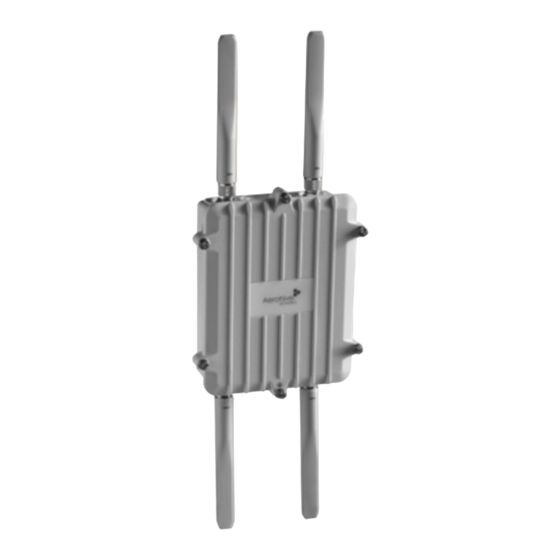
Chapter 3 The AP170 Platform The AP170 is a multi-channel mesh wireless access point with a watertight chassis that can be deployed in virtually any outdoor setting, including extreme environments. With four antennas and the ability to provide service concurrently on both 2.4 GHz and 5 GHz bands, the AP170 supports 802.11n and legacy 802.11a, b, and g clients. - Page 30 The Aerohive AP170 is specifically designed for outdoor high-bandwidth wireless deployments in harsh environments. The AP170 supports a variety of authentication and security protocols, including Wi-Fi CERTIFIED™ WPA™ and WPA2™, 802.11i, WEP, 802.1X, PSK, Aerohive’s patented PPSK, and AES:CCMP, TKIP, and RC4 (WEP only) encryption.
-
Page 31: Ap170 Product Overview
AP170 P RODUCT VERVIEW Table 1 AP170 hardware components (Continued) Component Description 10/100/1000 Ethernet The waterproof 10/100/1000 Ethernet port accepts standard Ethernet cat5, port cat5e, or cat6 Ethernet cable, and is powered from 802.3af-compatible power sourcing equipment (PSE). The pin assignments follow the TIA/EIA-568-B standard. -
Page 32: Installing The Ap170
To install the AP170, you must be a qualified installation professional, licensed or certified in accordance with local regulations. Use only attachments and accessories specified by Aerohive. During operation, the surfaces of the AP170 can become hot. Use caution when handling it. -
Page 33: Mounting The Ap170
AP170 OUNTING THE Do not locate the AP170 enclosure near overhead power lines or other electric light or power circuits, or where it can come into contact with such circuits. During installation, exercise extreme care not to come into contact with these circuits, which can cause serious injury or death. For proper installation and grounding of the product, refer to national and local electrical codes: NFPA (National Fire Protection Association) 70, National Electrical Code Article 810 (U.S.);... -
Page 34: Vertical Pole Mount
Hose strap 5. Connect the grounding cable to the grounding lug on the unit, as shown in Figure 5 on page Connect the other end of the cable to an appropriate ground. Aerohive... -
Page 35: Horizontal Pole Mount
AP170 OUNTING THE Horizontal Pole Mount The following steps explain how to mount the AP170 on a horizontal pole. 1. To mount the AP170 on a horizontal pole, first attach the plane bracket to the back of the unit using the four hex-head bolts with lock washers and flat washers. -
Page 36: Flat Surface Mount
Hex nut with lock washer and flat washer Mounting bolt 6. Connect the grounding cable to the grounding lug on the unit, as shown in Figure 5 on page Connect the other end of the cable to an appropriate ground. Aerohive... -
Page 37: Attaching External Antennas
5 GHz 5 GHz The omnidirectional antennas are available from Aerohive (SKUs AH-ACC-170-ANT-2G, AH-ACC-170-ANT-5G). These antennas fit the N-type antenna connectors on the top and bottom of the AP170. The two connectors on the bottom of the unit are for the 2.4 GHz antennas, and the two on the top of the unit are for the 5 GHz antennas (device and antennas are labeled). -
Page 38: Attaching The Ethernet Cable Waterproof Housing
However, the network where the Ethernet cable enters the building requires protection as well. To prevent the indoor network from power surges caused by lightning, place an Ethernet protector (SKU AH-ACC-1G-ETH-PROT) inline between the AP and the rest of the network as shown in Figure 7 on page Aerohive... - Page 39 THERNET ROTECTION Figure 7 Placement of Ethernet protector in relation to the network AP170 outdoors = Ethernet cable Indoors = Wireless link Switch Ethernet Outdoor PoE To network Protector injector PoE Switch Ethernet To network Protector Indoor PoE Ethernet To network Injector Protector Switch...
-
Page 40: Accessing The Internal Reset Switch
Remove the six screws that secure the cover of the AP170. Paper clip Reset switch Woven metal gasket Rubber gasket 3. Replace the top, being careful not to disturb the weatherproofing gaskets. 4. Tighten the six screws to secure the top to the chassis. Aerohive... -
Page 41: Device, Power, And Environmental Specifications
EVICE OWER NVIRONMENTAL PECIFICATIONS EVICE OWER NVIRONMENTAL PECIFICATIONS Understanding the range of specifications for the AP170 is necessary for optimal deployment and device operation. The following specifications describe the hardware components, PoE (Power over Ethernet) electrical requirements, and the environmental ranges in which the device can operate. Device and Enclosure Specifications •... - Page 42 Chapter 3 The AP170 Platform Aerohive...
-
Page 43: Chapter 4 The Ap320 Platform
Chapter 4 The AP320 Platform The Aerohive AP320 is a high-performance and highly reliable 802.11n wireless access point. The AP320 provides dual concurrent 802.11b/g/n and 802.11a/n radios for 3x3 MIMO (Multiple In, Multiple Out) and dual 10/100/1000 Ethernet ports for link aggregation or link redundancy. Its power management system uses a concept called smart PoE (Power over Ethernet) to adjust its power consumption automatically in response to the available power in different environments. -
Page 44: Ap320 Product Overview
Because the AP320 does not have an on/off switch, connecting it to a power source automatically powers on the device. Console port You can access the CLI by making a serial connection to the RJ45 console port. See "Console Port" on page Aerohive... -
Page 45: Ethernet Ports
Console Port Through the RJ45 console port, you can make a serial connection between your management system and the Aerohive device. The management station from which you make a serial connection to the AP320 must © have a VT100 emulation program, such as Tera Term Pro (a free terminal emulator) or Hilgraeve ®... -
Page 46: Reset Button
(heart-shaped) pattern around each antenna (see Figure 7 on page 116). The three 2.4-GHz antennas link to radio 1, and the three 5-GHz antennas link to radio 2. Conceptually, the relationship of antennas and radios is shown in Figure 2 on page Aerohive... -
Page 47: Mounting The Ap320
AP320 OUNTING THE Figure 2 Antennas and radios Radio 1 Radio 2 5 GHz 2.4 GHz RF 802.11a/n RF 802.11b/g/n Antennas Antennas 5 GHz 2.4 GHz Cut-away view of the AP to show the relationship of the antennas and the two internal radios The wifi0 interface links to radio 1 (frequency range = 2.4 GHz for IEEE 802.11b/g), and the wifi1 interface links to radio 2 (frequency range = 5 GHz for IEEE 802.11a). - Page 48 Pushing from the LED end of the AP, slide it toward the bottom end of the plate until the two rippled tabs on the mounting plate snap over the nubs on the underside of the When you are done, adjust the ceiling tiles back into their former position. Aerohive...
-
Page 49: Locking The Ap320
Torx tri-wing torsion insert bit for size #1 tri-wing security screws and a screw driver that will accept the bit. The correct bits are available from Aerohive in sets of three (AH-ACC-SEC-BIT-3PK). 1. Insert the security screw through the hole in the AP320 and begin to thread it into the hole in the... -
Page 50: Device, Power, And Environmental Specifications
RJ45 power input pins: Wires 4, 5, 7, 8 or 1, 2, 3, 6 Environmental Specifications • Operating temperature: 32 to 104 degrees F (0 to 40 degrees C) • Storage temperature: -4 to 158 degrees F (-20 to 70 degrees C) • Relative Humidity: Maximum 95% (noncondensing) Aerohive... -
Page 51: Chapter 5 The Ap340 Platform
Chapter 5 The AP340 Platform The Aerohive AP340 is a high-performance and highly reliable 802.11n wireless access point. The AP340 provides dual concurrent 802.11b/g/n and 802.11a/n radios for 3x3 MIMO (Multiple In, Multiple Out) and dual 10/100/1000 Ethernet ports for link aggregation or link redundancy. Its power management system uses a concept called smart PoE (Power over Ethernet) to adjust its power consumption automatically in response the available power in different environments. -
Page 52: Product Overview
See "Antennas" on page 10/100/1000 Mbps The two 10/100/1000-Mbps Ethernet ports—ETH0 and ETH1—support IEEE 802.3af and PoE ports 802.3at PoE (Power over Ethernet) and receive RJ45 connectors. See "Ethernet Ports" on page Aerohive... -
Page 53: Ethernet Ports
802.3at standard, such as one of the PoE injectors available as an optional accessory from Aerohive. (If you connect the AP to a power source through the power connector and PoE ports simultaneously, the device draws power through the power connector and automatically disables PoE.) You can configure ETH0 and ETH1 as two individual Ethernet interfaces, combine them into an aggregate interface to increase throughput, or combine them into a redundant interface to increase reliability. -
Page 54: Console Port
(steady): Wireless interface is in backhaul mode but inactive Amber • (flashing): Wireless interface is in backhaul mode and is connected with other hive members Green and amber • (alternating): Wireless interface is in backhaul mode and is searching for other hive members Aerohive... -
Page 55: Antennas
Ethernet ports. Connect the shorter antennas, which support 5 GHz frequencies (for IEEE 802.11a/n), to the connectors on the side panel with the device lock slot. For detailed information about how to configure external antennas on AP340 devices and other Aerohive devices that support them, see "Configuring Antennas"... -
Page 56: Mounting The Ap340
Figure 4 on page 55. When you have the mounting plate in the correct location, cut or drill a hole in the ceiling through which you can then pass the Ethernet and power cables. Aerohive... - Page 57 AP340 OUNTING THE Figure 4 Attaching the track clips and mounting plate to the ceiling track (Worms’s eye view with ceiling tiles removed for clarity) Press the track clips against the ceiling track and swivel them until they snap into Track clips Ceiling track place, gripping the edges of the track.
-
Page 58: Locking The Ap340
Hanger clip holes on either side of the larger hole. 3. Attach the AP340 to the mounting plate, and then attach the antennas to the connectors (see Figure 8 on page 57). Aerohive... - Page 59 AP340 OUNTING THE Figure 8 Attaching the AP340 to the mounting plate Hanger clip Align the V-shaped tabs on the mounting bracket with the tab Mounting plate slots on the bottom of the AP. Insert the V-shaped tabs into the tab slots until they click into place.
- Page 60 Hanger frame 7. Connect one or two Ethernet cables to the network, and—if not using PoE—connect the power cord to a power source. 8. Replace the ceiling tile to complete the installation. Aerohive...
-
Page 61: Suspended Mount
AP340 OUNTING THE Suspended Mount You can suspend the AP340 from a horizontal beam, post, strut, or girder. As well as the mounting plate, you ® need a quad-toggle, a 1.5 mm (0.059 inch) wire rope with hook, and a locking device. ERICO supplies ®... - Page 62 When you are satisfied, stop pressing against the tube so that it can regain its grip on the rope. Figure 13 Releasing the wire rope from the locking device Locking device Press against the lip of the inner tube and hold. Wire rope Screwdriver While pushing the tube inward, pull the wire rope out. Aerohive...
-
Page 63: Surface Mount
AP340 OUNTING THE Surface Mount You can use the mounting plate to attach the AP340 to any surface that supports its weight, and to which you can screw or nail the plate. First, mount the plate to the surface. Then, through one of the two large openings in the plate, make a hole in the wall so that you can pass the cables through to the AP. -
Page 64: Device, Power, And Environmental Specifications
RJ45 power input pins: Wires 4, 5, 7, 8 or 1, 2, 3, 6 Environmental Specifications • Operating temperature: -4 to 131 degrees F (-20 to 55 degrees C) • Storage temperature: -40 to 176 degrees F (-40 to 80 degrees C) • Relative Humidity: Maximum 95% Aerohive... -
Page 65: Chapter 6 Ap330 And Ap350 Platforms
Chapter 6 AP330 and AP350 Platforms The AP330 and AP350 are 802.11n wireless access points designed for greater throughput and range, with the added capability of being configured as routers. They provide dual concurrent 802.11b/g/n and 802.11a/n radios for 3x3 MIMO (Multiple Input Multiple Output) antenna configurations and three spatial streams. -
Page 66: Product Overview
ETH1 1 port connectors. For details, see "Ethernet Ports" on page Reset button The reset button allows you to reboot the device or reset the AP to its factory default settings. For details, see "Reset Button" on page Aerohive... -
Page 67: Ethernet Ports
AH-ACC-INJ-30W-IL If an Aerohive AP is connected to both an AC power source and PSE, the AC power source takes priority. If the device loses power from that source, it automatically switches to PoE. If the AC power comes back online, the AP automatically switches back to AC. -
Page 68: Reset Button
CLI, enter [ no ] system led brightness { soft | dim | off }. The various brightness levels are shown in Figure 2. (Although the AP330 is shown in the illustration, the same settings also apply to the AP350.) Figure 2 Status indicator brightness levels Brigh Soft Aerohive... -
Page 69: Antennas
RODUCT VERVIEW Antennas The AP330 has internal antennas, and the AP350 connects to detachable ones. Antennas for both models are described below. AP330 The AP330 has six internal single-band antennas. Three of the antennas operate in the 2.4 GHz band (IEEE 802.11b/g/n) with a 2-5 dBi gain. -
Page 70: Mounting The Ap330 Or Ap350
• 15/16" recessed ceiling rail mount For narrower tracks, you can order a pair of 9/16" rail mounts from Aerohive (AH-ACC-9-16-CLIP-330-AP350). One rail mount in the pair is flush and the other is recessed. If necessary, nudge the adjacent ceiling tiles slightly away from the track to clear some space. Attach the... -
Page 71: Surface Mount
AP330 AP350 OUNTING THE Figure 5 Attaching the AP to the rail mount With the AP upside down, align the two V-shaped tabs and the security tab extension on the rail mount with the tab slots and security screw cavity on the AP, and press the AP upward until it snaps into place. Security tab extension (side view) V-shaped tab... -
Page 72: Locking The Ap330 And Ap350
#6 security screws and a screw driver that will accept the bit. The correct bits are available from Aerohive in sets of three (AH-ACC-SEC-BIT-330-AP350-3PK). If you use the slotted screw, you can install it with a standard flat-blade screwdriver or driver bit. -
Page 73: Device, Power, And Environmental Specifications
EVICE OWER NVIRONMENTAL PECIFICATIONS EVICE OWER NVIRONMENTAL PECIFICATIONS Understanding the range of specifications for the AP330 and AP350 is necessary for optimal deployment and device operation. The following specifications describe the physical features and hardware components, the power adapter and PoE (Power over Ethernet) electrical requirements, and the temperature and humidity ranges in which the devices can operate. - Page 74 Chapter 6 AP330 and AP350 Platforms Aerohive...
-
Page 75: Chapter 7 The Sr2024 Switch
Chapter 7 The SR2024 Switch Aerohive SR2024 switches combine enterprise-class access switching with cloud-enabled management, on-demand provisioning, and secure routing in an advanced networking feature set for your network edge. This chapter covers the following topics: • "Product Overview" on page 74 •... -
Page 76: Product Overview
Chapter 7 The SR2024 Switch RODUCT VERVIEW The Aerohive SR2024 Switch provides advanced network edge features including cloud-enabled management, on-demand provisioning, and secure branch routing. The SR2024 offers Gigabit Ethernet switching and advanced features that include user-based QoS, storm control, 802.1x multiple authentication for voice and data, as well as traditional switching features such as LLDP, Spanning Tree, 3G/4G connectivity, and IGMP snooping. -
Page 77: Ethernet Ports
109). The ports accept standard cat3, cat5, cat5e, or cat6 Ethernet cable, and autosensing capabilities allow the wiring termination in the Ethernet cable to be either straight-through or crossover. For PoE ports, especially with 803.2at, Aerohive recommends using cat5 or cat 6 Ethernet cable. PoE and PoE+ Ports The SR2024 offers PoE (power over Ethernet) or PoE+ on ports ETH1 through Eth8 to power PDs (powered devices) such as VoIP phones, wireless access points, and network cameras. -
Page 78: Poe Power Management
Port priorities are assigned and changed using the PSE port profiles that you create in HiveManager. Add PSE profiles for low, high, and critical in your network policy in HiveManager. You can change the priority for a port by changing its PSE profile. Aerohive... -
Page 79: Console Port
WAN is not possible, you can use the USB modem as the primary (and only) interface to the WAN. Before you can use a modem with any Aerohive device, you must first have the modem activated. You can have this done in the store where you purchased the modem, or you can install software such as the Verizon... -
Page 80: Installing Or Replacing An Sfp Module
(do not allow it to evaporate slowly) and has not collected in crevices of cavities. Alcohol residue can contaminate connectors and it is difficult to remove all traces of it. For this reason, a dry cleaning process is preferable. Aerohive... -
Page 81: Fans
RODUCT VERVIEW Fans The SR2024 switch has four cooling fans which, by default, are always on. You can view fan status and temperature levels in HiveManager. The fan speeds and temperature settings are preconfigured. Make sure the switch fans have enough space for proper cooling (see "Mounting and Installation"... - Page 82 With PoE mode selected: Dark: PoE power is not active on this port Power Link Amber: Port is providing 802.3at-rated PoE Speed Stack Green: Port is providing 802.3af-rated PoE Amber (flashing): There is a PoE error on Duplex this port Reset LEDs Aerohive...
-
Page 83: Mounting And Installation
OUNTING AND NSTALLATION OUNTING AND NSTALLATION Install SR series switches on a clean, level desktop or surface, or in a standard equipment rack using the rack mount kit that ships with the switch. Figure 4 shows how to mount the switch in a rack. Adequate ventilation is critical for switch operation. -
Page 84: Device, Power, And Environmental Specifications
Storage temperature: -4° to 158° F (-20 to 70° C) • Operating humidity: 5% to 95% (non-condensing) • Altitude (operating and storage): 10,000 ft (3000 m) • Low noise: Less than 48 dBA at full power • Temperature-controlled fan speed Aerohive... -
Page 85: Chapter 8 The Br100 Router
Chapter 8 The BR100 Router Based on the Aerohive HiveOS operating system, the compact BR100 router requires virtually no intervention from the end user. The BR100 gives small offices and teleworkers full Layer 3 network capability with local DHCP and DNS services, centralized management, and firewall and VPN security. -
Page 86: Product Overview
Ethernet ports on the rear panel. For details, see "USB Modem Port" on page Link status LEDs There are link status LEDs for the WAN port and LAN Ethernet ports on the rear panel. For details see "USB Modem Port" on page Aerohive... - Page 87 RODUCT VERVIEW Table 1 BR100 router component descriptions (Continued) Component Description Power connector The DC 12V/1A connector port allows you to connect the router to an appropriate power source using the AC/DC power adapter (included). Because the router does not have an on/off switch, connecting it to a power source automatically powers on the device.
-
Page 88: Radio And Antennas
Aircard 310U, 312U, and 320U) can also be used with these routers. Before you can use a modem with an Aerohive device, you must first have the modem activated. You can have this done in the store where you purchased the modem, or you can install software such as the Verizon... -
Page 89: Status Leds
OUNTING AND NSTALLATION Status LEDs The device status LED on the angled edge of the BR100 indicates various states of activity by color (dark, amber, and white) and illumination pattern (steady glow or flashing). The link status LEDs indicate link activity for the ports by color (dark, green) and illumination pattern (steady glow or flashing). -
Page 90: Device, Power, And Environmental Specifications
AC power adapter: • Input: 100 - 240 VAC • Output: 12V/1A Environmental Specifications • Operating temperature: 32°F to 104°F (-0 to 40°C) • Storage temperature: -4°F to 158°F (-20 to 70°C) • Relative humidity: 5 to 95% (noncondensing) Aerohive... -
Page 91: Chapter 9 Br200 And Br200-Wp Routers
Chapter 9 BR200 and BR200-WP Routers Based on the Aerohive HiveOS operating system, the compact Aerohive BR200 series routers give branch offices and teleworkers full Layer 3 network capability with local DHCP and DNS services, centralized management, and firewall and IPsec VPN security. There are two BR200 models; the BR200 and the BR200-WP. -
Page 92: Product Overview
RODUCT VERVIEW Aerohive BR200 series routers are a critical component of the Branch-on-Demand solution, which allows enterprises to provision branch office networks and teleworkers quickly and easily. Aerohive BR200 series routers are available in two models: the BR200-WP and the BR200. The BR200-WP provides LAN and WLAN connectivity and PoE (Power over Ethernet) support. -
Page 93: Radio And Antennas
RODUCT VERVIEW Table 1 BR200 series routers component descriptions Component Description Device status LED The device status LED is located on the triangular wedge on the top of the device. This LED conveys operational states for system power, firmware upgrades, connectivity with HiveManager, and WAN failover states. -
Page 94: Ethernet Ports
Ethernet cable can be either straight-through or crossover. For PoE ports, especially with 803.2at, Aerohive recommends using cat5 or cat 6 Ethernet cable. On BR200 series routers, each of these ports represent a separate logical interface. For this reason, you can apply multiple LAN profiles (one for each of the four ports). -
Page 95: Reset Button
Aircard 310U, 312U, and 320U) can also be used with these routers. Before you can use a modem with an Aerohive device, you must first have the modem activated. You can have this done in the store where you purchased the modem, or you can install software such as the Verizon... -
Page 96: Status Leds
0.25" (0.64 cm) so that they will fit inside the openings in the keyholes. Place the wide section of keyholes over the screws and press the device down to secure it to the wall. Aerohive... -
Page 97: Device, Power, And Environmental Specifications
EVICE OWER NVIRONMENTAL PECIFICATIONS EVICE OWER NVIRONMENTAL PECIFICATIONS Understanding the range of specifications for the BR200 series routers is necessary for optimal deployment and device operation. The following specifications describe the hardware components, electrical requirements, and the environmental ranges in which the device can operate. Device and Enclosure Specifications •... - Page 98 Chapter 9 BR200 and BR200-WP Routers Aerohive...
-
Page 99: Chapter 10 The High-Capacity 1U Hivemanager Appliance
Chapter 10 The High-Capacity 1U HiveManager Appliance The1U High-Capacity HiveManager appliance, (AH-HM-1U), provides centralized configuration, monitoring, and reporting for multiple Aerohive devices. Some of the benefits that the HiveManager High-Capacity 1U appliance offers include: • Simplified installation and management of up to 8000 devices •... - Page 100 European governments have more strict regulations on the disposal of rechargeable batteries than the USA and Canada. Check the laws and regulations where you live before disposing of lithium batteries. Aerohive...
-
Page 101: Product Overview
RODUCT VERVIEW RODUCT VERVIEW The Aerohive 1U High Capacity HiveManager Appliance is a central management system for configuring and monitoring devices. You can see the hardware components in Figure 1 and read a description of each component in Table 5 "HiveManager Appliance component descriptions". -
Page 102: Ethernet And Console Ports
Parity: none • Stop bits: 1 • Flow control: none admin Aerohive The default login name is and the password is . After making a connection, you can access the Linux operating system. Status LEDs The LEDs on the front panel of the HiveManager appliance indicate the status for power and hard disk drive activity through their color (dark or green) and illumination patterns (steady glow or blinking). -
Page 103: Rack Mounting The Hivemanager Appliance
OUNTING THE ANAGER PPLIANCE OUNTING THE ANAGER PPLIANCE You can mount the HiveManager Appliance in a standard 19" (48 cm) equipment rack using standard rack screws—typically 3/4”, 1/2”, or 3/8” long with 10-32 threads—and matching washers. The HiveManager ships with two mounting brackets and six bracket attachment screws. Install the mounting brackets at either the front or middle of each side of the device (depending on whether you want a front-mount or mid-mount position, and attach the HiveManager Appliance in the rack using standard rack screws and washers (see Figure... - Page 104 Environmental Specifications • Operating temperature: 32 to 104 degrees F (0 to 40 degrees C) • Storage temperature: -4 to 158 degrees F (-20 to 70 degrees C) • Relative Humidity: 5% – 95% (non-condensing) Aerohive...
-
Page 105: Chapter 11 The Hivemanager Platform
Chapter 11 The HiveManager Platform The HiveManager Network Management System provides centralized configuration, monitoring, and reporting for multiple Aerohive devices. The following are a few of the many benefits that HiveManager offers: • Simplified installations and management of up to 500 devices •... -
Page 106: Product Overview
Chapter 11 The HiveManager Platform RODUCT VERVIEW The Aerohive HiveManager is a central management system for configuring and monitoring devices. You can see the hardware components in Figure 1 and read a description of each component in Table 1 "HiveManager component descriptions". -
Page 107: Ethernet And Console Ports
RODUCT VERVIEW Table 1 HiveManager component descriptions (Continued) Component Description AC power inlet The three-prong AC power inlet is a C14 chassis plug through which you can connect a HiveManager to a 100 – 240-volt AC power source using the 10-amp/125-volt IEC power cord that ships with the product. -
Page 108: Rack Mounting The Hivemanager
2. Insert a screw through a washer, the hole in one of the mounting brackets, and a hole in the rail. 3. Tighten the screw until it is secure. 4. Repeat steps 2 and 3 to secure the other side of the HiveManager to the rack. Aerohive... -
Page 109: Device, Power, And Environmental Specifications
EVICE OWER NVIRONMENTAL PECIFICATIONS EVICE OWER NVIRONMENTAL PECIFICATIONS Understanding the range of specifications for the HiveManager is necessary for optimal deployment and operation of the device. The following specifications describe the physical features and hardware components, the electrical requirements for the power supply and cord, and the temperature and humidity ranges in which the device can operate. - Page 110 Chapter 11 The HiveManager Platform Aerohive...
-
Page 111: Appendix A Wiring Diagrams And Antenna Orientation
The following sections contain pin assignments and wiring information for standard and PoE (power over Ethernet) Ethernet ports for Aerohive devices. Standard (non-PoE) Ethernet Port Pin Assignments Standard (non-PoE) Ethernet ports in Aerohive devices follow the TIA/EIA-568-B standard. Figure 1 shows the pin assignments and port LEDs for a non-PoE Ethernet port. -
Page 112: Power Over Ethernet Port Pin Assignments
(PSE) that is 802.3af-compatible. If you use cat5, cat5e, or cat6 cables, Aerohive PoE devices can also support 802.3at-compliant PSE. Such equipment can be embedded in a switch or router, or it can come from purpose-built devices that inject power into the Ethernet line en route to the device. -
Page 113: Smart Poe
T568B. Smart PoE The AP320, AP340, BR200-WP, and SR2024 switch apply the Aerohive concept of smart PoE (power over Ethernet) to adjust power consumption as necessitated by varying levels of available power. The AP340 and BR200-WP support PoE on the ETH0 or ETH1 interfaces and can draw power through either one or through both simultaneously. -
Page 114: Aggregate And Redundant Interfaces
Switch(config-if)#exit Switch(config)#int fastEthernet 0/2 Switch(config-if)#switchport mode access Switch(config-if)#channel-group 1 mode on Switch(config-if)#spanning-tree portfast Switch(config-if)#exit Switch(config)#exit Switch#wr mem Finally, you must cable the Cisco switch and the AP together: Cisco 0/1 to AP eth0, and Cisco 0/2 to AP eth1. Aerohive... -
Page 115: Redundant Interface
RJ45 C ONSOLE SSIGNMENTS Redundant Interface If a single Ethernet link provides sufficient bandwidth and speed, such as a 1000 Mbps link, but you want to ensure link redundancy, you can connect the two Ethernet ports to the same switch—or to two different switches—and configure them to act as a redundant interface called "red0". -
Page 116: Db9 Console Port Pin Assignments
DB9 C ONSOLE SSIGNMENTS Some Aerohive devices have a male DB9 serial Console port that allows you to make a console connection using an RS-232 (or "null modem") cable. The management station from which you make a serial connection ©... -
Page 117: Configuring Antennas
As anyone who has administered a WLAN system knows, configuring the antennas correctly at the outset can save you lots of trouble. The external antennas on many Aerohive devices are adjustable, and can be patch, directional (single-direction), and omnidirectional antennas. The type of antenna you use determines the coverage pattern. -
Page 118: Omnidirectional Antennas
To accomplish this, the transmitter separates a single data stream into multiple spatial streams, one for each RF chain (an antenna + various digital signal processing modules linked to the antenna). The transmit antennas at the end of each RF chain then transmit their spatial streams. The Aerohive... - Page 119 MIMO recipient’s receive antennas obtain streams from all the transmit antennas. In fact, due to multipath, they receive multiple streams from each transmit antenna. The receive antennas pass the spatial streams to the digital signal processors in their RF chains, which take the best data from all the spatial streams and reassemble them into a single data stream once again (see Figure Figure 8...
-
Page 120: Using Mimo With Legacy Clients
802.11a and 802.11g clients. To do that, enter the following command: no radio profile <string> allow-11b-clients By blocking access to 802.11b clients, their slower data rates cannot clog the WLAN when the amount of wireless traffic increases. Aerohive... -
Page 121: Index
30 radios 12 mounting 31–36 reset button 10, 11 mounting, flat surface 34 status indicator 10, 11 mounting, horizontal pole 33 AP120 9–16 mounting, vertical pole 32 antennas 16 PoE 36 environmental specifications 16 power specifications 39 Ethernet port 10... - Page 122 LEDs, See individual platform entries device status LED 91, 94 environmental specifications 95 Ethernet ports 91, 92 MIMO (Multiple In, Multiple Out) 116–118 hardware specifications 95 link status LED 91, 94 locking 91 mounting and installation 94 power connector 91 BR200-WP 91 Aerohive...
- Page 123 Index dynamic power management 76 console port 74, 77 smart PoE 111 device and enclosure specifications 82 static power management 76 environmental specifications 82 Ethernet ports 75 guard band power settings 76 radios, See individual platform entries hardware components 74 reboot, APs 10, 19, 43, 51, 64 hardware specifications 82 redundant interfaces 113...
- Page 124 Index Aerohive...
Need help?
Do you have a question about the AP120 and is the answer not in the manual?
Questions and answers