
Subscribe to Our Youtube Channel
Related Manuals for CIAT AQUALIS 2 Series


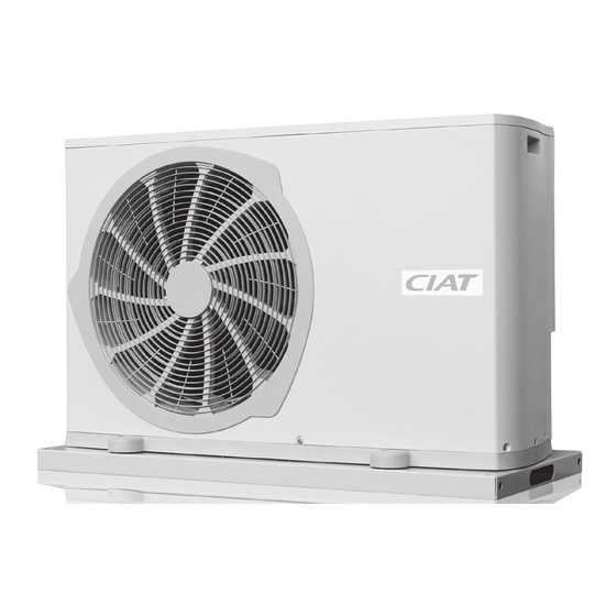
Summary of Contents for CIAT AQUALIS 2 Series
- Page 1 N 06.126C 04 - 2008 Installation Installation Operation Fonctionnement Commissioning Mise en service Maintenance Maintenance Montage- Installazione Betriebs-und Funzionamento Wartungs- Avviamento Anweisung Manutenzione...
-
Page 2: Table Of Contents
CONTENTS PAGE 1 ) GENERAL 1.1 Introduction 1.2 Unpacking the equipment 1.3 Identifying the equipment 1.4 Warranty 1.5 Safety recommendation 1.6 Declaration of conformity 2 ) INSTALLATION 2.1 Location of the control terminal and the heat pump 2.1.1 Location of the control terminal 2.1.2 Location of the unit 2.1.3 Weight and handling 2.1.4 Dimensions... -
Page 3: Introduction
The information on the plate (particularly the description and the serial number) must be quoted in all correspon- dence. 1.4 Warranty For information on obtaining service under the CIAT warranty, please refer to the general terms and conditions of sale. 1.5 Safety recommendation 1.6 Declaration of conformity... -
Page 4: Location Of The Control Terminal And The Heat Pump
INSTALLATION 2.1 Location of the control terminal and the heat pump 2-1-1 Location of the control terminal On delivery, the control terminal can be found inside the machine, near the electrical box (open top to access it). Specifications - Settings stored in memory for two hours following a power cut - Blue backlit digital display - Maximum dimensions: 128 x 85 x 31 mm - Wall mounting plate... -
Page 5: Location Of The Unit
2-1-2 Location of the heat pump The installer must check the following points before handling, placing or connecting the unit: - The unit is intended for use outdoors, near a building, on a deck/patio or in a garden. Although it is rain resistant, it may be installed under a shelter with adequate ventilation on all four sides. If you plan on heating more than cooling, place the unit in a sunny location. -
Page 6: Weight And Handling
Nothing should obstruct the free flow of air over the air-cooled heat exchanger (suction and discharge) . Protect from prevailing winds 2-1-3 Weight and handling Now that you have chosen a location for your unit, you may begin installing it. Bear in mind the weight and dimensions given in this section. -
Page 7: Hydraulic Connections
2.2 Hydraulic connections In order to meet the operating conditions (flow rates, pressure losses) , a sizing calculation must be performed. The diameters of the tubes are not necessarily the same as those of the unit. 2-2-1 Pipe connections Diameters of water connections 20 / 28 / 35 50 / 65 / 75 MODEL... -
Page 8: Condensate Water
2-2-5 Condensate water Drainage of condensate water in heating mode Caution: if this connection is used when the outdoor temperature drops below dia. 25 mm 0°C, necessary precautions must be taken to protect the water in the drain pipe We recommend using a heat from freezing. - Page 9 b - Connection to TUs 4-bar safety Automatic valve bleed (required) (required) Control terminal Check valve + gauge HEAT HEATER (option) Hoses PUMP Charging (to be insulated) HW tank + buffer tank (optional) Filter )An expansion vessel is necessary if the water capacity of the system is higher than that given in the table of technical specifications in section 7.1. c - Connection to an RFHC and TUs Control 4-bar safety...
-
Page 10: Frost Protection
2-2-8 Frost protection (for the account of installer) If your Aqualis 2 system is located in an area subjected to below-freezing temperatures, you must add glycol to the water in it. 2-2-8.1 Protecting your system To protect your heating system and avoid all risks of it freezing in case it is intentionally or accidentally turned off, we strongly advise that you: Either drain the water circuit by disconnecting the unit inlet and outlet), Or take the following precautions:... -
Page 11: Electrical Connections
(e.g. NF C 15100 in France) and are under the responsibility of the installer. Failure to comply with the requirements of the above standards will void the CIAT warranty. It is your responsibility to protect the unit from mains voltage spikes and voltage spikes caused by lightning. Depending on the geographic location and the type of mains network (buried or overhead), you may have to install a lightning rod. - Page 12 Connections to be made before commissioning the unit Control In bypass only mode: terminal remove the jumper Common between terminals 4 and 5 Bypass 5 4 3 2 1 5 4 3 2 1 Frost protection or Heating/Cooling TERMINAL BLOCK J1 5 4 3 2 1 5 4 3 2 1 TERMINAL...
-
Page 13: Checks
Wire cross-sections and electrical specifications The cross-section of the cable must be selected with care based on: - the maximum current rating of the unit (see electrical specifications table below) , - the distance between the electrical box and Aqualis 2, - the ambient temperature. -
Page 14: Bleeding The Air
Pressure or temperature measurements requiring the use of gauges should be taken only if the unit malfunctions and doing so is recommended by CIAT’s After- Sales Service. To keep your unit running smoothly and to benefit from the warranty, take out a maintenance contract with your installer or an approved maintenance company. -
Page 15: Aqualis 2 Operating Readings
4.1 Aqualis 2 operating readings D a t e / T i m e Suction pressure Suction temperature °C Condensation pressure Condensation temperature °C Gas/liquid inlet temperature °C Gas/liquid outlet temperature °C Air inlet temperature °C Air outlet temperature °C Water inlet temperature °C Water outlet temperature... -
Page 16: Overview
CONTROL 5.1 Overview The unit is controlled by the following components: Single-phase Control terminal Electronic control Three-phase PSU board with display board PSU board Reversible model Single-phase PSU board Cooling only model 5.2 The terminal unit and its display 5-2-1 Display on the terminal unit screen Screen µ... -
Page 17: Position Of The Dial (No. 14) On The Terminal Unit
5-2-2 Position of the dial (No. 14) on the terminal unit A - Reversible units Buttons Dial Mode Display position Advance Reverse the minutes. the minutes. Time and day adjustment, Go to following day Minutes advance quickly Minutes reverse quickly unit off Clock when pressed and held. - Page 18 Setting Factory Setting Description setting value 1 = AQUALIS Unit version 2 = AQUALIS 2 0 = pure water Glycol content 1 = glycol/water mix 0 = input not used On/Off input on 1= input used to force heating and cooling modes J2, terminals 3-5 2 = input used to place unit in frost protection mode by remote control 0 = radiators/fan coil units or combined with floor (TU)
- Page 19 Setting Factory Setting Description setting value 0 = no pool or humidity sensor options Pool 1 = pool management and humidity sensor options configura- 2 = humidity sensor management tion 3 = pool + humidity sensor management Pool water setpoint 20°C to 35°C 28°C Self-regulating frosting time...
-
Page 20: Operating Modes
5.3 Operating modes Adjust setting P3 as shown in the table below depending on your system and the desired operating mode. TU system TU + RFHC system RFHC system P03 = 0 P03 = 0 P03 = 1 The room temperature setpoint is displayed on the terminal unit / COOLING mode The unit will adjust the temperature based on the room temperature setpoint and the out-... -
Page 21: Electrical Auxiliary Unit P6 = 1 Or
5-4-1 Electrical auxiliary unit: P6 = 1 or 2 a - Operating limits Maximum Auxiliaries may be used if the outdoor temperature Operating limits temperature is below < P7 (trigger threshold). back to Control is carried out on interstage differential P21. Heat pump and auxiliaries off heat pump Example: P21 = 2°C and water setpoint P42 = 40°C... -
Page 22: On/Off Control Inputs
b - Boiler controlled by the Microconnect microprocessor: P6 = 5 Application: boiler with basic control When P6 is set to ‘5’, the burner and the heat pump are controlled by the Microconnect microprocessor using the water formu- la entered in the terminal unit (settings P15 to P19). The room temperature is managed by the Microconnect terminal. Heat pump and boiler operating ranges Operating limits Heat pump and boiler off... -
Page 23: Control Board
5.6 Control board CPU board description Location of connector and terminal blocks TERMINAL BLOCK J2 TERMINAL BLOCK J1 1-2 Control terminal (12 V) ‚ ‚ auxiliary output 1 ‚ ‚ auxiliary output 2 Heating/Cooling - Unoccupied control ‚ ‚ On/Off - bypass input auxiliary output 3 ‚... -
Page 24: Components
5.7 Components 5-7-1 External fans Cooling mode 1 - Fan starts at high speed 5 seconds before the compressor starts. 2 - Fan speed adjusted based on the outdoor air temperature then the freon temperature. 3 - Fan continues running for 30 seconds after the compressor stops. Heating mode 1 - Fan starts at high speed 5 seconds before the compressor starts. -
Page 25: Functions
5.8 Functions 5-8-1 Automatic restart In the event of a power cut, the unit automatically resumes the mode it was in after a period of 3 minutes. 5-8-2 Short-cycle protection The unit is authorised to start back up if the compressor is turned off for at least 3 minutes. 5-8-3 Automated self-regulating control This function adjusts the compressor running time or the stage differential to best adapt the operation of the unit to the type of installation. -
Page 26: Temporary And Permanent
FAULTS 6.1 Temporary and permanent There are two types of fault: temporary and permanent - Temporary faults cause the unit to enter fault-tolerant mode and the fault type flashes on the terminal LCD. Temporary faults are not stored in memory and the fault relay is not stuck in a particular position (exceptions: terminal link fault and fault d4.9). - Permanent faults shut down the unit and, depending on the settings, activate the auxiliaries. -
Page 27: Acknowledging Faults
6.3 Acknowledging faults After diagnosing and eliminating the cause of a fault, acknowledge it by pressing OK on the terminal for 3 seconds with the dial turned to Off. 6.4 Sensor values CTN sensors, 10 k at 25°C Temperature Sensor resist- Temperature Sensor resist- Temperature... -
Page 28: Technical Specifications
SPECIFICATIONS 7.1 Technical specifications AQUALIS 2 20 / 20 H 28 / 28 H 35 / 35 H 50 H 35T / 35 HT 50T / 50 HT 65T / 65 HT 75T / 75 HT Quantity Type SCROLL Compressor 1.25 1.66 1.25... -
Page 29: Available Pressure Curves (Pure Water)
7.3 Available pressure curves (pure water) The available pressure curves are given for pure water. Subtract 5 kPa from the available pressures in the case of systems using 40% monopropylene glycol (heating mode). 20 - 20H 28 - 28H AQUALIS 2 AQUALIS 2 Water flow (m Water flow (m... - Page 30 Documento non contrattuale. Dans le souci constant, thought material Aufgrund ständigen CIAT si riserva il diritto di Verbesserung seiner Geräte, d’améliorer matériel, improvement always in mind, apportare, modiche tecniche dettate behält sich CIAT das Recht vor, CIAT se réserve le droit de CIAT reserves the right, without dall’evoluzione costante dei suoi...
Need help?
Do you have a question about the AQUALIS 2 Series and is the answer not in the manual?
Questions and answers