
Subscribe to Our Youtube Channel
Related Manuals for Freescale Semiconductor KIT33912EVME


Summary of Contents for Freescale Semiconductor KIT33912EVME
- Page 1 Freescale Semiconductor Document Number: KT33912UG User’s Guide Rev. 2.0, 10/2009 KIT33912EVME System Basis Chip with LIN Tranceiver Setup Instructions © Freescale Semiconductor, Inc., 2007 - 2009. All rights reserved.
- Page 2 Opportunity/Affirmative Action Employer. Freescale and the Freescale Logo are registered in the US Patent and Trademark Office. All other product or service names are the property of their respective owners. KIT33912EVME System Basis Chip with LIN Transceiver Setup Instructions Setup Instructions, Rev. 2.0 Freescale Semiconductor...
-
Page 3: Table Of Contents
SPI Status Control Registers Tab Panels ..............17 System Status Register and SPI Status Registers ............18 Sequence Pane ......................19 Chapter 6 Embedded Slave Software KIT33912EVME System Basis Chip with LIN Tranceiver Setup Instructions, Rev. 2.0 Freescale Semiconductor TOC-1... - Page 4 Jumper Connection ....................... 31 Appendices Appendix A Quick Guide ......................34 Appendix B Schematics ......................35 Appendix C Placement and Layout ..................38 Appendix D Bill of Materials ....................40 KIT33912EVME System Basis Chip with LIN Tranceiver Setup Instructions, Rev. 2.0 TOC-2 Freescale Semiconductor...
- Page 5 Schematics - MCU ..................36 Figure B-3. Schematics - Loads ..................37 Figure C-1. Placement Top ....................38 Figure C-2. Copper Top ....................38 Figure C-3. Copper Bottom (mirrored) ................39 System Basis Chip with LIN tranceiver Setup Instructions, Rev. 0.0 Freescale Semiconductor LOF-1...
- Page 6 KIT33912EVME System Basis Chip with LIN Tranceiver Setup Instructions, Rev. 2.0 LOF-2 Freescale Semiconductor...
- Page 7 MCU Pins not used in the Application ............29 Table 9-8. ISENSE Connector Pin Out................30 Table 10-1. Jumper Connection ..................31 Table D-1. Bill of Materials ....................40 KIT33912EVME System Basis Chip with LIN Tranceiver Setup Instructions, Rev. 2.0 Freescale Semiconductor LOT-1...
- Page 8 KIT33912EVME System Basis Chip with LIN Tranceiver Setup Instructions, Rev. 2.0 LOT-2 Freescale Semiconductor...
-
Page 9: Preface
Preface Preface This User’s Guide provides the installation steps for the KIT33912EVME System Basis Chip with LIN Transceiver (SBCLIN) Audience This document is intended for application developers who are setting up Freescale’s KIT33912EVME System Basis Chip with LIN Transceiver. Suggested Reading Additional documentation on the FreeMASTER software may be found at www.freescale.com. -
Page 10: Chapter 1 Sbclin Evaluation Module Kit
— monitor supporting a screen resolution of 1280x1024 recommended — one or two serial ports (COM) — CD-ROM drive — ≥ 45 MB hard disk drive space KIT33912EVME System Basis Chip with LIN Tranceiver Setup Instructions, Rev. 2.0 Freescale Semiconductor... -
Page 11: Sbclin Evaluation Module Kit Quick Guide
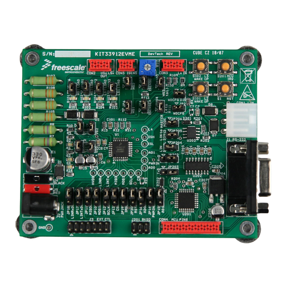
SBCLIN Evaluation Module Kit quick guide. NOTE This Evaluation Module Kit isn’t appointed for EMC tests of MC33912 device. KIT33912EVME Figure 1-1. SBCLIN Evaluation Module Kit KIT33912EVME System Basis Chip with LIN Tranceiver Setup Instructions, Rev. 2.0 Freescale Semiconductor... -
Page 12: Chapter 2 Setup Instructions
Results: The License Agreement box is displayed and you are prompted for further actions. Figure 2-1. License Agreement Box Clicking the Next button will start the installation program. Results: The Installation Wizard will prompt you for further actions. KIT33912EVME System Basis Chip with LIN Tranceiver Setup Instructions, Rev. 2.0 Freescale Semiconductor... -
Page 13: Figure 2-2. Freemaster Installation
Figure 2-2. FreeMASTER Installation Follow the instructions given by the Installation Wizard. Install the GUI. Start the GUIxx.exe installation file. Results: The Installation Wizard will prompt you for further actions. KIT33912EVME System Basis Chip with LIN Tranceiver Setup Instructions, Rev. 2.0 Freescale Semiconductor... -
Page 14: Figure 2-3. Graphical User Interface Installation Wizard
Setup Instructions Figure 2-3. Graphical User Interface Installation Wizard KIT33912EVME System Basis Chip with LIN Tranceiver Setup Instructions, Rev. 2.0 Freescale Semiconductor... -
Page 15: Quick System Setup To Run The Sbclin Evaluation Module
For communication from the MCU to a personal computer, through FreeMASTER protocol, place Jumpers JP202 (TxD) and JP203 (RxD) in positions 1-2, which connect the MCU and the TTL / RS232 converter. Configure the KIT33912EVME to an on-board control, by ensuring that Jumpers JP10 - JP16 and JP19 - JP20 are in position 1-2. -
Page 16: Start Graphic User Interface
Figure 2-5. Graphical User Interface Initialization Screen Default serial port setting is COM1/9600Bd. To choose a different setting, select from the main menu Project -> Options ->Comm. KIT33912EVME System Basis Chip with LIN Tranceiver Setup Instructions, Rev. 2.0 Freescale Semiconductor... -
Page 17: Figure 2-6. Graphical User Interface Welcome Screen
Choose the User Helpful button to open the page with a user friendly environment and FreeMASTER communication; Chapter 5, User Helpful Control Page Figure 2-6. Graphical User Interface Welcome Screen KIT33912EVME System Basis Chip with LIN Tranceiver Setup Instructions, Rev. 2.0 Freescale Semiconductor... -
Page 18: Chapter 3 Freemaster Control Page
FreeMASTER Control Page Chapter 3 FreeMASTER Control Page Overview The section describes basic guide to controlling the KIT33912EVME board by the FreeMASTER control page. • 3.2, Setup Instruction • 3.3, Description of the Control GUI • 3.4, SPI Registers Control/Status Array •... -
Page 19: Spi Registers Control/Status Array
If the MC33912 device generates an interrupt, then a read of the Interrupt Source Register is automatic and its value is displayed on the ISR register indicators row, so that the user recognizes the interrupt occurring. KIT33912EVME System Basis Chip with LIN Tranceiver Setup Instructions, Rev. 2.0 Freescale Semiconductor... -
Page 20: Pulse Width Modulation
WD ON. When there is a direct connection of the watchdog terminal to the ground, the watchdog service is disabled automatically. KIT33912EVME System Basis Chip with LIN Tranceiver Setup Instructions, Rev. 2.0 Freescale Semiconductor... -
Page 21: Wake-Up Sources
(WUCR, HSCR, TIMCR, CFR, MCR) will be send to the device. The device will then enter one of the low power mode. Figure 3-5. Wake-up Configuration Panel KIT33912EVME System Basis Chip with LIN Tranceiver Setup Instructions, Rev. 2.0 Freescale Semiconductor... -
Page 22: Chapter 4 Lin Master Control Page
LIN Master Control Page Chapter 4 LIN Master Control Page Overview This section shows control of the KIT33912EVME board from the control page through LIN communication protocol. • 4.2, Setup Instruction • 4.3, Description of the Control GUI • 4.4, LIN Port Control... -
Page 23: Lin Port Control
LIN Master Control Page LIN Port Control KIT33912EVME board includes a LIN communication channel. For communication through LIN, stop the FreeMASTER communication port. Select COMx port in section LIN PORT:, then start communication by clicking the STOP button, see; Figure 4-2. -
Page 24: Chapter 5 User Helpful Control Page
User Helpful Control Page Chapter 5 User Helpful Control Page Overview This section provides an overview on how to control the KIT33912EVME board from the User Helpful control page. The aim of this control environment is simplify control of the evaluation module. •... -
Page 25: Spi Status Control Registers Tab Panels
Access to the other tab panels is possible by clicking on the abbreviated register names, located above and below the panel. Figure 5-2. Status Register Tab Panel KIT33912EVME System Basis Chip with LIN Tranceiver Setup Instructions, Rev. 2.0 Freescale Semiconductor... -
Page 26: System Status Register And Spi Status Registers
Interrupt Source Register is automatic and its value is displayed on the Status Register array, and also on the ISR tab panel, so that the user recognizes the interrupt occurring. KIT33912EVME System Basis Chip with LIN Tranceiver Setup Instructions, Rev. 2.0 Freescale Semiconductor... -
Page 27: Sequence Pane
Other blocks such as Pulse Width Modulation, SPI Watchdog, Last Error Message, Graph, Wake-up Sources and Variable Watch Pane are described in Chapter 3, FreeMASTER Control Page, and their functionality is similar. KIT33912EVME System Basis Chip with LIN Tranceiver Setup Instructions, Rev. 2.0 Freescale Semiconductor... -
Page 28: Chapter 6 Embedded Slave Software
Generic Control is uses Free NAD values, meaning that the NAD value must be selected from the range 128 (0x80) - 255 (0xFF), and not to be interpreted as a diagnostic. For the KIT33912EVME NAD - 160 (0xA0) is used. -
Page 29: 6.2.2 Cmd Data Interpretation
A/D converter register, which is separated into two bytes. This command uses bytes S0, S1, S2 and S3. The message structure is described as follows: KIT33912EVME System Basis Chip with LIN Tranceiver Setup Instructions, Rev. 2.0 Freescale Semiconductor... -
Page 30: Mcu Reprogram
S4 - 0xFF S5 - 0xFF MCU Reprogram In case of loose the MCU embedded code, it is possibility to reprogram MCU flash memory from file on CD...\GraphicalUserInterface\Project.abs.s19. KIT33912EVME System Basis Chip with LIN Tranceiver Setup Instructions, Rev. 2.0 Freescale Semiconductor... -
Page 31: Chapter 7 Freemaster Activex Object
7.2.1 WriteVariable Function Example // write to FreeMASTER variable, display error box in case of error function write_fmaster_variable(varname, value){ var succ = pcm.WriteVariable(varname, value); if (!succ) set_fmaster_err(); KIT33912EVME System Basis Chip with LIN Tranceiver Setup Instructions, Rev. 2.0 Freescale Semiconductor... -
Page 32: 7.2.2 Readvariable Function Example
// read FreeMASTER variable, display error box in case of error on success, value is returned function read_fmaster_variable(varname){ var value var succ = pcm.ReadVariable(varname); if(succ){ value = pcm.LastVariable_vValue; }else{ set_fmaster_err(); return value; KIT33912EVME System Basis Chip with LIN Tranceiver Setup Instructions, Rev. 2.0 Freescale Semiconductor... -
Page 33: Chapter 8 Activex Lin Master Object
VBScript handler. The Sleep mode is aborted by a call to the Wakeup, SendMessage or RecvMessage functions. Even in the OnWakeup event, you remain in the Sleep mode until one of these three functions is called. KIT33912EVME System Basis Chip with LIN Tranceiver Setup Instructions, Rev. 2.0 Freescale Semiconductor... - Page 34 LastRecvDataLength; — This property retrieves the number of bytes received by the last RecvMessage() call • property: string LastErrorMsg; — This property retrieves the last error message. KIT33912EVME System Basis Chip with LIN Tranceiver Setup Instructions, Rev. 2.0 Freescale Semiconductor...
-
Page 35: Overview
6 pin connector. Table 9-2. J201 Program Debug Terminal Definition Terminal Terminal Name Definition BKGD Background debug. Ground. No connect. RESET Reset. No connect. +5V voltage supply. KIT33912EVME System Basis Chip with LIN Tranceiver Setup Instructions, Rev. 2.0 Freescale Semiconductor... -
Page 36: J3 External Control
Table 9-4 shows the three pin connector standard definition. Table 9-4. LIN Connector Pin Out Terminal Terminal Name Definition LGND LIN ground. VBAT Supply voltage LIN interconnect terminal KIT33912EVME System Basis Chip with LIN Tranceiver Setup Instructions, Rev. 2.0 Freescale Semiconductor... -
Page 37: Con2 Hsx Lsx Outputs
+5V output supply terminal. See Table 9-7. Table 9-7. MCU Pins not used in the Application Terminal Terminal Name Definition HVDD Hall sensor switchable supply terminal. PTD0 Not used in application. KIT33912EVME System Basis Chip with LIN Tranceiver Setup Instructions, Rev. 2.0 Freescale Semiconductor... -
Page 38: Con5 Isense Inputs
Table 9-8. ISENSE Connector Pin Out Terminal Terminal Name Definition PGND Power ground. ISENSEH Current sense differential (+) input. PGND Power ground. ISENSEL Current sense differential (-) input. KIT33912EVME System Basis Chip with LIN Tranceiver Setup Instructions, Rev. 2.0 Freescale Semiconductor... -
Page 39: Chapter 10 Jumper Connection
1-2 position: SPI Chip Select (CS) is connected from MCU to MC33912 2-3 position: SPI Chip Select (CS) is connected from J3 header to MC33912 Floating: (CS) is not connected KIT33912EVME System Basis Chip with LIN Tranceiver Setup Instructions, Rev. 2.0 Freescale Semiconductor... - Page 40 1-2 position: MCU output (TxD) is connected to MAX232 converter 2-3 position: LIN physical interface MCZ33661EF output (TxD) is connected to MAX232 converter Floating: SCI output of MAX232 is disconnected KIT33912EVME System Basis Chip with LIN Tranceiver Setup Instructions, Rev. 2.0 Freescale Semiconductor...
- Page 41 Floating: LIN signal from LIN physical interface MCZ33661EF is not connected JP206 1-2 position: LIN pull-up resistor and diode are connected {Master Mode} Floating: LIN pull-up resistor and diode are disconnected {Slave Mode} KIT33912EVME System Basis Chip with LIN Tranceiver Setup Instructions, Rev. 2.0 Freescale Semiconductor...
-
Page 42: Appendices
Quick Guide Appendices Appendix A Quick Guide CON2 CON5 CON2 CON2 J4,J5 J201 CON4 Figure A-1. Quick Guide KIT33912EVME System Basis Chip with LIN Tranceiver Setup Instructions, Rev. 2.0 Freescale Semiconductor... -
Page 43: Appendix B Schematics
Schematics Appendix B Schematics Figure B-1. Schematics - System Basis Chip KIT33912EVME System Basis Chip with LIN Tranceiver Setup Instructions, Rev. 2.0 Freescale Semiconductor... -
Page 44: Figure B-2. Schematics - Mcu
Schematics Figure B-2. Schematics - MCU KIT33912EVME System Basis Chip with LIN Tranceiver Setup Instructions, Rev. 2.0 Freescale Semiconductor... -
Page 45: Figure B-3. Schematics - Loads
Schematics Figure B-3. Schematics - Loads KIT33912EVME System Basis Chip with LIN Tranceiver Setup Instructions, Rev. 2.0 Freescale Semiconductor... -
Page 46: Appendix C Placement And Layout
Placement and Layout Appendix C Placement and Layout Figure C-1. Placement Top Figure C-2. Copper Top KIT33912EVME System Basis Chip with LIN Tranceiver Setup Instructions, Rev. 2.0 Freescale Semiconductor... -
Page 47: Figure C-3. Copper Bottom (Mirrored)
Placement and Layout Figure C-3. Copper Bottom (mirrored) KIT33912EVME System Basis Chip with LIN Tranceiver Setup Instructions, Rev. 2.0 Freescale Semiconductor... -
Page 48: Appendix D Bill Of Materials
JP10, JP11, JP12, JP13, HDR_1X3 JP14, JP15, JP16, JP17, Header 3X1, Diameter 2.54 JP18, JP19, JP20, JP202, JP203 D Subminiature Connector, 5747844-6 DC_POWER_JACK Power Jack, Pin Dia 2.1mm, PJ-102AH KIT33912EVME System Basis Chip with LIN Tranceiver Setup Instructions, Rev. 2.0 Freescale Semiconductor... - Page 49 32pin, MC9S08DZ60MLC U202 MAX3232ESE RS232/TTL converter, Maxim-Dallas, MAX3232ESE+ U203 MCZ33661EF LIN Driver, MCZ33661EF U204 LM2931DT-5.0G Linear Voltage Regulator 5V, 100mA, LM2931DT-5.0G Not refer Jumper Jumper Socket KIT33912EVME System Basis Chip with LIN Tranceiver Setup Instructions, Rev. 2.0 Freescale Semiconductor...
- Page 50 Freescale Semiconductor product could create a situation where personal injury or death may occur. Should Buyer...
Need help?
Do you have a question about the KIT33912EVME and is the answer not in the manual?
Questions and answers