
Subscribe to Our Youtube Channel
Related Manuals for Freescale Semiconductor KIT22XS4200EKEVB


Summary of Contents for Freescale Semiconductor KIT22XS4200EKEVB
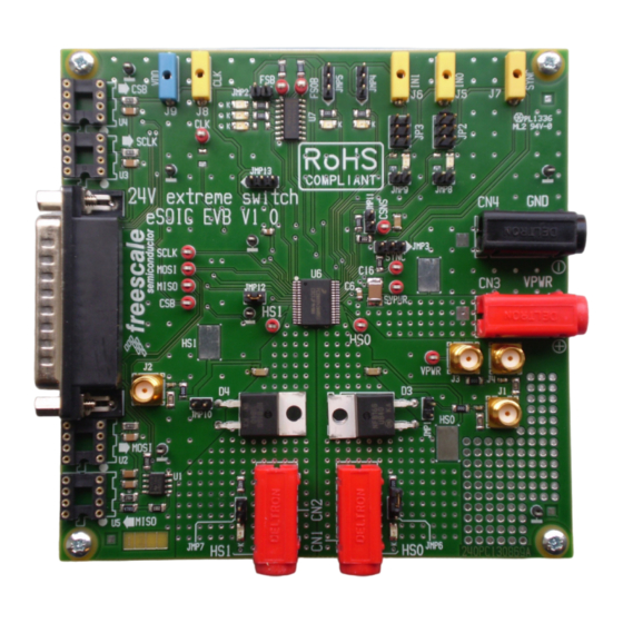
- Page 1 Freescale Semiconductor, Inc. Document Number: KT22XS4200UG User’s Guide Rev. 1.0, 9/2014 KIT22XS4200EKEVB Evaluation Board Figure 1. KIT22XS4200EKEVB © Freescale Semiconductor, Inc., 2014. All rights reserved.
-
Page 2: Table Of Contents
10 Revision History ..................27 KT22XS4200UG Rev. 1.0 Freescale Semiconductor, Inc. -
Page 3: Important Notice
Freescale was negligent regarding the design or manufacture of the part.Freescale™ and the Freescale logo are trademarks of Freescale Semiconductor, Inc. All other product or service names are the property of their respective owners. © Freescale Semiconductor, Inc. 2014 KT22XS4200UG Rev. -
Page 4: Getting Started
Getting Started Getting Started Kit Contents/Packing List The KIT22XS4200EKEVB contents include: • Assembled and tested evaluation board/module in anti-static bag. • Quick Start Guide, Analog Tools • Warranty card Jump Start Freescale’s analog product development boards help to easily evaluate Freescale products. These tools support analog mixed signal and power solutions including monolithic ICs using proven high-volume SMARTMOS mixed signal technology, and system-in-package devices utilizing power, SMARTMOS and MCU dies. -
Page 5: Getting To Know The Hardware
Getting to Know the Hardware Board Overview The KIT22XS4200EKEVB demonstrates the capability of the MC22XS4200 as a 24 V dual high-side switch that provides integrated control with protective and diagnostic functions. This product has been designed for truck, bus, and industrial applications. The low R channels (<... - Page 6 Getting to Know the Hardware Board Description Figure 2 describes the main blocks of the KIT22XS4200EKEVB. Over Ext. Direct Sync output current CLK FSB, FOSB, inputs profile input RSTB LEDs Optic fiber interface (not mounted) MC22XS4200 Power supply inputs SPI connector Sense Free wiring ...
- Page 7 SPI Interface 25 pin connector for SPI communication MC22XS4200 Device high-side switch 22 mΩ output LED Display The following LEDs are provided as visual output devices for the KIT22XS4200EKEVB evaluation board: D5, D6 & D7 D8 & D9 D10 & D11 Figure 3. LED Display KT22XS4200UG Rev. 1.0...
- Page 8 JMP5 connected between position 1 & 2 ON when CONF0 = DC motor ON when IN0 = High JMP8 connected ON when IN1 = High JMP9 connected ON when HS0= High JMP6 connected ON when HS1= High JMP7 connected KT22XS4200UG Rev. 1.0 Freescale Semiconductor, Inc.
- Page 9 Table 4. Connectors Connector ID Description Output high-side switch channel 0 Output high-side switch channel 1 VPWR, 6.0 to 58 V GND, ground reference Direct input for channel 0 Direct input for channel 1 KT22XS4200UG Rev. 1.0 Freescale Semiconductor, Inc.
- Page 10 9. CONF1 10. NC 11. NC 12. MISO 13. NC 14. NC 15. NC 16. FSOB 17. FSB 18. NC 19. NC 20. GND 21. NC 22. NC 23. NC 24. NC 25. NC KT22XS4200UG Rev. 1.0 Freescale Semiconductor, Inc.
- Page 11 SYNC Current sense synchronization Fault status FSOB Fail-safe output CSNS Output current sense monitoring PWM clock TP10 SCLK SPI serial clock TP11 MISO Serial Output (SO) TP12 Chip select TP13 MOSI Serial Input (SI) KT22XS4200UG Rev. 1.0 Freescale Semiconductor, Inc.
- Page 12 The following table defines the evaluation board jumper positions and explains their functions. Table 7. Jumper Definitions Jumper Description Setting Connection Diode not connected A diode is connected between ground and JMP1 high-side output channel 0 (HS0) Diode connected KT22XS4200UG Rev. 1.0 Freescale Semiconductor, Inc.
- Page 13 Note: Recommended position for regular use of SYNC signal SYNC is directly connected to the 1 mm banana plug, the SYNC signal is not connected to pull-up resistor. In that configuration, an external pull-up resistor is required outside the EVB. KT22XS4200UG Rev. 1.0 Freescale Semiconductor, Inc.
- Page 14 JMP12 Device GND Device connected to GND RSTB is internally tied to GND RSTB is connected to connector DB25 (JP1) JMP13 RSTB state RSTB is connected to VDD (5.0 V), device cannot be reseted KT22XS4200UG Rev. 1.0 Freescale Semiconductor, Inc.
-
Page 15: Accessory Interface Board
Accessory Interface Board Accessory Interface Board The KIT22XS4200EKEVB kit may be used with the KITUSBSPIEVME interface dongle (shown below), which provides a USB-to-SPI interface. This small board makes use of the USB, SPI, and parallel ports built into Freescale’s MC68HC908JW32 microcontroller. The main function provided by this dongle is to allow Freescale evaluation kits having a parallel port to communicate via a USB port to a PC. - Page 16 Accessory Interface Board Connecting KITUSBSPIEVME to the Board without DB25 Cable The KITUSBSPIEVME can be directly connected to the KIT22XS4200EKEVB as shown in Figure Figure 8. Connecting KITUSBSPIEVME to the Board without DB25 Cable KT22XS4200UG Rev. 1.0 Freescale Semiconductor, Inc.
-
Page 17: Installing The Software And Setting Up The Hardware
9. The text at the top is the name of the configuration file loaded. The left side panel displays folders that group user interfaces. The process of loading the configuration file has assigned a list of “Extra Pins” as well as a list of “Quick Commands”, all of which are board-specific. Figure 9. SPIGen GUI KT22XS4200UG Rev. 1.0 Freescale Semiconductor, Inc. - Page 18 Configuring the Hardware The KIT22XS4200EKEVB operates with a single DC power supply from 6.0 to 58 V, and is fully controlled via the SPI with the help of an USB-SPI KITUSBSPIEVME EVB kit, requiring a 5.0 V DC power supply.
- Page 19 1. Ready the computer and install the SPIGen. 2. To start working with KIT22XS4200EKEVB, provide 24 V input voltage between 6.0 to 58 V, by connecting the (+) probe to the VPWR pin, and the (-) probe to the GND pin, on the input power terminal block.
- Page 20 Set RSTB to level high by entering Extra Pins in the Session Log text box • Set Control0 = High • Set Bit 6 of SO to 1 • Click Send Once Figure 13. SPD22 Initialization KT22XS4200UG Rev. 1.0 Freescale Semiconductor, Inc.
- Page 21 Click Send One Command at a Time • Select Init for the setup • Click Send Once • Session Log displays log of send and receive commands Figure 14. Alternate Initialization Sequence with Batch Commands KT22XS4200UG Rev. 1.0 Freescale Semiconductor, Inc.
- Page 22 Select Out0 Fully On from the list • Click Send Once • Session Log displays log of send and receive commands Result : The bulb connected to HS0 is turned on. Figure 15. Single Command Sequence KT22XS4200UG Rev. 1.0 Freescale Semiconductor, Inc.
-
Page 23: Schematic
Schematic Schematic Figure 16. Evaluation Board Schematic KT22XS4200UG Rev. 1.0 Freescale Semiconductor, Inc. -
Page 24: Board Layout
Board Layout Board Layout Silkscreen KT22XS4200UG Rev. 1.0 Freescale Semiconductor, Inc. -
Page 25: Board Bill Of Materials
Freescale does not assume liability, endorse, or warrant components from external manufacturers are referenced in circuit drawings or tables. While Freescale offers component recommendations in this configuration, it is the customer’s responsibility to validate their application. Critical components. For critical components, it is vital to use the manufacturer listed. KT22XS4200UG Rev. 1.0 Freescale Semiconductor, Inc. -
Page 26: References
KITUSBSPIEVME Tool Summary Page http://www.freescale.com/webapp/sps/site/prod_summary.jsp?&code=SPIGEN SPIGen Reference Product Summary Page Support Visit www.freescale.com/support for a list of phone numbers within your region. Warranty Visit www.freescale.com/warranty for a list of phone numbers within your region. KT22XS4200UG Rev. 1.0 Freescale Semiconductor, Inc. -
Page 27: Revision History
Revision History Revision History Revision Date Description of Changes 9/2014 • Initial Release KT22XS4200UG Rev. 1.0 Freescale Semiconductor, Inc. - Page 28 Freescale and the Freescale logo are trademarks of Freescale Semiconductor, Inc., Reg. U.S. Pat. & Tm. Off. SMARTMOS is a trademark of Freescale Semiconductor, Inc. All other product or service names are the property of their respective owners. © 2014 Freescale Semiconductor, Inc.
Need help?
Do you have a question about the KIT22XS4200EKEVB and is the answer not in the manual?
Questions and answers