
Related Manuals for Freescale Semiconductor KIT33882EKEVB


Summary of Contents for Freescale Semiconductor KIT33882EKEVB
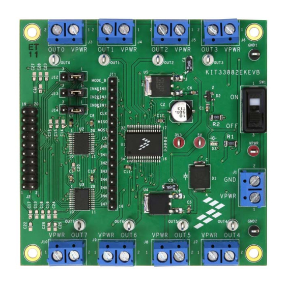
- Page 1 Freescale Semiconductor Document Number: KT33882UG Rev. 1.0, 12/2014 User’s Guide KIT33882EKEVB Evaluation Board Figure 1. KIT33882EKEVB © Freescale Semiconductor, Inc., 2014. All rights reserved.
-
Page 2: Table Of Contents
10 Revision History ....................23 KT33882UG, Rev. 1.0 Freescale Semiconductor, Inc. -
Page 3: Important Notice
Freescale was negligent regarding the design or manufacture of the part. Freescale™ and the Freescale logo are trademarks of Freescale Semiconductor, Inc. All other product or service names are the property of their respective owners. -
Page 4: Getting Started
Getting Started Getting Started 2.1 Kit Contents/Packing List The KIT33882EKEVB contents include: • Assembled and tested evaluation board/module in an anti-static bag • Quick Start Guide, Analog Tools • One 20-pin ribbon cable • Warranty card 2.2 Jump Start Freescale’s analog product development boards help to easily evaluate Freescale products. These tools support analog mixed signal and power solutions including monolithic ICs using proven high-volume SMARTMOS mixed signal technology, and system-in-package devices utilizing power, SMARTMOS and MCU dies. -
Page 5: Getting To Know The Hardware
Getting to Know the Hardware 3.1 Board Overview The KIT33882EKEVB evaluation board is an easy-to-use circuit board that allows the user to exercise all the functions of the MC33882 Smart Six Output Switch (0.3 Ohm R ) with SPI and Parallel Input Control. -
Page 6: Block Diagram
• Daisy chain operation of multiple devices possible • Switch outputs can be paralleled for higher currents • R of 0.4 Ohm per output (25 °C) at 13 V VPWR DS(on) • SPI operation guaranteed to 2.0 MHz KT33882UG, Rev. 1.0 Freescale Semiconductor, Inc. -
Page 7: Board Description
• Allows a FSD to be connected to the evaluation board via a 20-pin ribbon cable • Provides test points for various signals (See Test Point Definitions on page 8 for more in- Test Points formation) Power and Ground Inputs • Provides connection points for power and ground KT33882UG, Rev. 1.0 Freescale Semiconductor... -
Page 8: Led Display
• Six output low-side switch with SPI and parallel input control 3.6 LED Display The following LED is provided as a visual output device for the KIT33882EKEVB evaluation board: LED D3 indicates when VPWR is present 3.7 Test Point Definitions The following test points provide access to signals on the MC33882 IC: Table 3. - Page 9 SPI signal - Serial In DATA4 DATA4 Connected to MODE_B SPI0-MISO SPI0_MISO SPI signal, Serial Out CTRL0 CNTL0 Connected to IN4 or IN0&IN1 via a jumper SPI0-CLK SPI0_CLK SPI signal - Serial Clock CTRL1 CNTL1 Connected to IN5 KT33882UG, Rev. 1.0 Freescale Semiconductor...
- Page 10 SPI1-MOSI <NC> <unused> 3.11 Screw Terminal Connections The KIT33882EKEVB board features screw terminal connections to allow easy access to the MC33882 signals and supply rails. Figure 4 shows the board locations and names of the screw terminals. Output Terminals FSD Connector...
-
Page 11: Jumper Definitions
Jumpers (J12, J13, J14) DATA4 (MODE_B) Dual IN Control 0&1, 2&3, 4&5 Position 2-3 HIGH IN Control 0, 1, 2, 3, 4, 5, 6, 7 Position 1-2 SPI Control 0, 1, 2, 3, 4, 5 KT33882UG, Rev. 1.0 Freescale Semiconductor... -
Page 12: Freedom Development Platform
Freedom Development Platform Freedom Development Platform The KIT33882EKEVB kit may be used with the FSD (see Figure 5), which provides a USB-to-SPI interface. This small board makes use of the USB, SPI and parallel ports built into Freescale's KL25Z microcontroller. The main function provided by this dongle is to allow Freescale evaluation kits that have a parallel port to communicate via a USB port to a PC. -
Page 13: Installing The Software And Setting Up The Hardware
During the installation, there is a request to select components to install. This kit requires Kinetis which also must be installed. User must install at least the Kinetis component. Select Kinetis and click on "Next" to complete the installation. KT33882UG, Rev. 1.0 Freescale Semiconductor... - Page 14 Installing the Software and Setting up the Hardware Figure 7. Choose Components GUI KT33882UG, Rev. 1.0 Freescale Semiconductor, Inc.
- Page 15 Ready the computer, install the SPIGen software. Make sure the FRDM board has been flashed with the correct SPIGen srec file. Connect the FRDM-KL25Z board to the KIT33882EKEVB evaluation board via the 20-pin ribbon cable. The FRDM-KL25Z board must have a 20-pin male header soldered onto the top of the FRDM-KL25Z board in J2.
- Page 16 Ready the computer. Only a USB port to provide power is required. (Make sure the FRDM board has been flashed with the correct srec file). Connect the FRDM-KL25Z board to the KIT33882EKEVB evaluation board via the 20-pin ribbon cable. The FRDM-KL25Z board must have a 20-pin male header soldered onto the top of the FRDM-KL25Z board in J2.
-
Page 17: Schematic
Schematic Schematic Figure 9. Schematic KT33882UG, Rev. 1.0 Freescale Semiconductor... -
Page 18: Silkscreens
Silkscreens Silkscreens 7.1 Silkscreen Top KT33882UG, Rev. 1.0 Freescale Semiconductor, Inc. - Page 19 Silkscreens 7.2 Silkscreen Bottom Notes: This image is an exception to the standard top-view mode of representation used in this document. It has been flipped to show a bottom view. KT33882UG, Rev. 1.0 Freescale Semiconductor...
-
Page 20: Bill Of Materials
HDR 1X16 TH 100 MIL SP 330 H TSW-116-07-S-S AU 100 L J12,J13,J14 HDR 1x3 TH 100 MIL SP 343 H SN TSW-103-07-T-S 100 L OUT1, OUT2, OUT3, OUT4, OUT5, TEST POINT WHITE 70X220 MIL 5007 OUT6, OUT7, OUT0 KT33882UG, Rev. 1.0 Freescale Semiconductor, Inc. - Page 21 Freescale does not assume liability, endorse, or warrant components from external manufacturers that are referenced in circuit drawings or tables. While Freescale offers component recommendations in this configuration, it is the customer’s responsibility to validate their application. Do not populate. Critical components. For critical components, it is vital to use the manufacturer listed. KT33882UG, Rev. 1.0 Freescale Semiconductor...
-
Page 22: References
FRDM-KL25Z http://www.freescale.com/webapp/sps/site/prod_summary.jsp?code=FRDM-KL25Z Development Platform Software SPIGen http://www.freescale.com/files/soft_dev_tools/software/device_drivers/SPIGen.html Software CodeWarrior http://www.freescale.com/webapp/sps/site/homepage.jsp?code=CW_HOME&tid=vanCODEWARRIOR Support Visit www.freescale.com/support for a list of phone numbers within your region. Warranty Visit www.freescale.com/warranty for a list of phone numbers within your region. KT33882UG, Rev. 1.0 Freescale Semiconductor, Inc. -
Page 23: Revision History
Revision History Revision History Revision Date Description of Changes 12/2014 • Initial Release KT33882UG, Rev. 1.0 Freescale Semiconductor... - Page 24 Freescale and the Freescale logo are trademarks of Freescale Semiconductor, Inc., Reg. U.S. Pat. & Tm. Off. SMARTMOS is a trademark of Freescale Semiconductor, Inc. All other product or service names are the property of their respective owners. © 2014 Freescale Semiconductor, Inc.
Need help?
Do you have a question about the KIT33882EKEVB and is the answer not in the manual?
Questions and answers