
Subscribe to Our Youtube Channel
Related Manuals for Freescale Semiconductor kinetis TWR-SMPS-LVFB


Summary of Contents for Freescale Semiconductor kinetis TWR-SMPS-LVFB
- Page 1 TWR-SMPS-LVFB Quick Start Guide Low-Voltage, Full-Bridge Power Conversion Module Tower System Development Board for Switch Mode Power Supply...
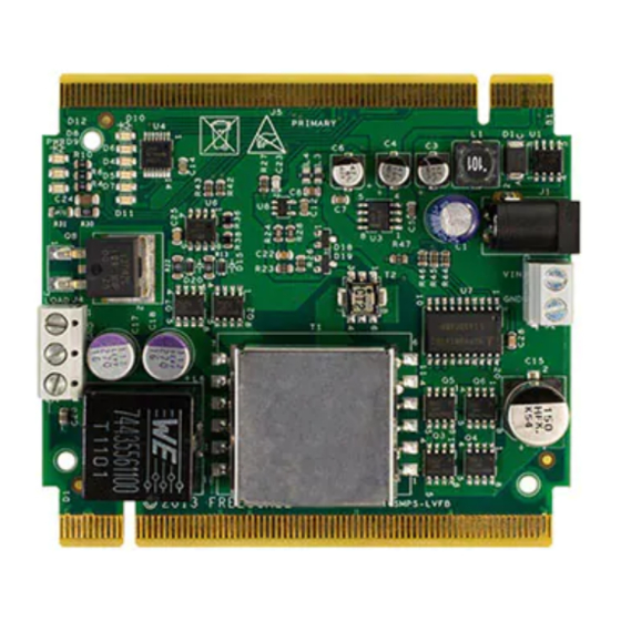
- Page 2 Quick Start Guide Get to Know the TWR-SMPS-LVFB MOSFET H-Bridge Secondary Elevator J4: Output Load J5: Input from DC Connector Power Source Dynamic J1: Input from Load Circuit AC-DC Adapter Auxiliary LEDs Power Supply Circuit Primary Elevator Figure 1: Front side of TWR-SMPS-LVFB TWR-SMPS-LVFB Tower System Module Freescale Tower System The TWR-SMPS-LVFB module is part of the Freescale Tower System,...
- Page 3 freescale.com Introduction to TWR-SMPS-LVFB Tower System Module The TWR-SMPS-LVFB Tower System Module is a development kit that can be used in conjunction with the Tower System development platform, providing ready-made software and hardware development for a low-voltage, full-bridge DC-DC switch mode power supply and using various control algorithms.
- Page 4 Quick Start Guide Step-by-Step Hardware Installation Instructions Attach Load Assemble Your Resistor Setup Tower System Attach the load resistor setup to output • Locate the Elevator modules identifiable connector J4 (output load connector) on by the four card edge connectors on the TWR-SMPS-LVFB: each.
- Page 5 freescale.com Step-by-Step Hardware Installation Instructions Connect DC Running Power Supply A Demo Connect the DC power supply provided in Please refer to freescale.com/ the kit to connector J1. If using an external TWR-SMPS-LVFB to understand what power supply then the input voltage range MCU controller cards are supported, and on J5 should be 20 to 30V DC and the to download a Quick Start Guide to learn...
- Page 6 Quick Start Guide TWR-SMPS-LVFB Tower System Module Demo The TWR-SMPS-LVFB Tower System demonstration implements average current mode control of full bridge converter and is implemented on the TWR-KV46F150M controller card. Other cards are also supported. Refer to freescale.com/TWR-SMPS-LVFB for the full list of supported controller cards. For more details, refer to the TWR-KV46F150M Quick Start Guide for TWR-SMPS-LVFB on freescale.com/TWR-KV46F150M.
- Page 7 freescale.com...
-
Page 8: Get Started
Freescale, the Freescale logo and Kinetis are trademarks of Freescale Semiconductor, Inc., Reg. U.S. Pat. & Tm. Off. Tower is a trademark of Freescale Semiconductor, Inc. ARM and Cortex are registered trademarks of ARM Limited (or its subsidiaries) in the EU and/or elsewhere. All rights reserved.
Need help?
Do you have a question about the kinetis TWR-SMPS-LVFB and is the answer not in the manual?
Questions and answers