Table of Contents
Advertisement
Quick Links
Summary:
1.
How to connect the wires: .................................................................................................................... 5
2.
Reference .............................................................................................................................................. 6
3.
Default settings ..................................................................................................................................... 6
NMT MESSAGES ............................................................................................................................................. 7
4.
Start CANopen node (keypad activation message) .............................................................................. 7
5.
Enter pre-operational ........................................................................................................................... 7
6.
Reset CANopen node ............................................................................................................................ 7
7.
Stop CANopen node ............................................................................................................................. 8
8.
Boot-up service ..................................................................................................................................... 8
9.
Heartbeat message ............................................................................................................................... 8
10. Sync message ........................................................................................................................................ 8
PDO messages ............................................................................................................................................... 9
11. Keys state message ............................................................................................................................... 9
•
PKP 2200LI .......................................................................................................................................... 9
12. Set LED ON message ........................................................................................................................... 10
•
Standard mode ................................................................................................................................. 10
•
Alternative mode ............................................................................................................................. 10
13. Set LED Blink message ........................................................................................................................ 11
•
Standard mode ................................................................................................................................. 11
•
Alternative mode ............................................................................................................................. 11
14. LED indicators brightness level ........................................................................................................... 12
15. Backlight setting ................................................................................................................................. 12
SDO Messages: ............................................................................................................................................ 13
16. Object 2000h: Digital input module, keys states ................................................................................ 13
•
PKP 2200LI ........................................................................................................................................ 13
17. Object 2001h: Digital output module. ................................................................................................ 14
Set LED ON .......................................................................................................................................... 14
•
PKP 2200LI ........................................................................................................................................ 14
Read LED ON ....................................................................................................................................... 14
•
PKP 2200LI ........................................................................................................................................ 14
18. Object 6001h: Digital output module. ................................................................................................ 15
Set LED ON .......................................................................................................................................... 15
•
PKP2200LI ......................................................................................................................................... 15
Read LED ON ....................................................................................................................................... 15
•
PKP2200LI ......................................................................................................................................... 15
PKP2200LI CANopen
Advertisement
Table of Contents

Subscribe to Our Youtube Channel
Related Manuals for Blink Marine PKP2200LI


Summary of Contents for Blink Marine PKP2200LI
-
Page 1: Table Of Contents
PKP 2200LI ............................14 Read LED ON ............................14 • PKP 2200LI ............................14 18. Object 6001h: Digital output module....................15 Set LED ON ............................15 • PKP2200LI ............................15 Read LED ON ............................15 • PKP2200LI ............................15... - Page 2 Set LED blink ............................17 • PKP 2200LI ............................17 Read LED blink ............................ 17 • PKP2200LI ............................17 21. Object 2003h: Brightness Level ......................18 LED indicators brightness level: ....................... 18 b) Backlight brightness level ......................... 18 Backlight color ..........................19 d) Default backlight color ........................
- Page 3 43. Object 1600h: Receive PDO mapping Parameter 0 ................37 44. Object 1601h: Receive PDO mapping Parameter 1 ................38 45. Object 1602h: Receive PDO mapping Parameter 2 ................38 46. Object 1603h: Receive PDO mapping Parameter 3 ................39 47.
- Page 4 NOTE: this document complies with the following CAN in Automation (CiA) specifications: • 301 (CANopen application layer and communication profile) • 401 (Device profile for generic I/O modules) 4/50 www.blinkmarine.com PKP2200LICANopenUM_REV1.3...
-
Page 5: How To Connect The Wires
1. How to connect the wires: COLOUR FUNCTION Blue CAN L White CAN H Black Negative battery Vbatt. (12-24V) Each end of the CAN bus is terminated with 120Ω resistors in compliance with the standard to minimize signal reflections on the bus. You may need to place a 120Ω resistor between CAN-L and CAN-H. -
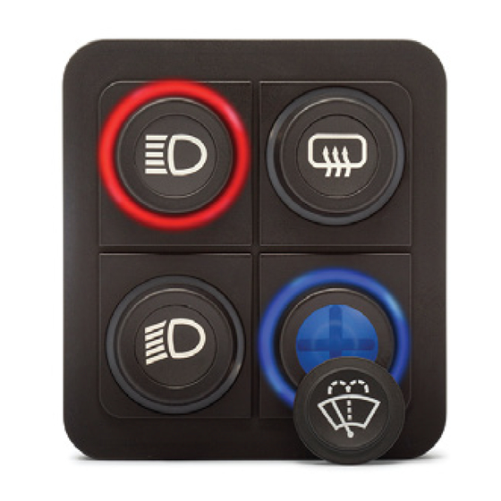
Page 6: Reference
2. Reference Front view. PKP2200LI 3. Default settings Setting Default state or level How to change Baud Rate 125 kbit/s Object 2010h CANopen Node ID Object 2013h Device active on startup Not active Object 2012h Key Brightness 3Fh (Maximum Brightness) -
Page 7: Nmt Messages
NMT MESSAGES The Network Management messages follow a master-slave structure. Through NMT services, CANopen devices are initialized, started, reset or stopped. NMT messages have CAN-ID always equal to 00h. 4. Start CANopen node (keypad activation message) Identifier Byte 0 Start CANopen node Keypad CAN ID Byte 1 00h: start all the Keypads... -
Page 8: Stop Canopen Node
7. Stop CANopen node Identifier Byte 0 02h: Stop CANopen node 00h: Stop CANopen node (old PKP sw compatibility) Byte 1 Keypad CAN ID 00h: stop all the Keypads 15h: stop the Keypad with CAN ID = 15h. Byte 2, 7 Not used Example: Direction... -
Page 9: Pdo Messages
PDO messages PDO (Process Data Object) are fast telegram messages that can simply manage most important functions. There are no answers for this kind of messages. Each PDO message has an equivalent Service Data Object message. 11. Keys state message The keypad must be activated, see NMT Start CANopen Node message. -
Page 10: Set Led On Message
12. Set LED ON message The keypad must be activated, see NMT Start CANopen Node message. • Standard mode Identifier 200h + current CAN ID Default 215h Byte 0 0 0 0 0 – R4 R3 R2 R1 Red LED Byte 1 0 0 0 0 –... -
Page 11: Set Led Blink Message
13. Set LED Blink message The keypad must be activated, see NMT Start CANopen Node message. Note: if the blink message is sent when the LED is already ON, the LED blinks in alternate mode. • Standard mode Identifier 300h + current CAN ID Default 315h Byte 0 0 0 0 0 –... -
Page 12: Led Indicators Brightness Level
14. LED indicators brightness level The keypad must be activated, see NMT Start CANopen Node message. NOTE: this setting has temporary effect and at the startup comes back to the default level. If the default level is desired to change, please refer to the object 2003h sub-index 05h. -
Page 13: Sdo Messages
SDO Messages: A SDO (Service Data Object) is providing direct access to object entries of a CANopen device's object dictionary. 16. Object 2000h: Digital input module, keys states This module contains all the Switch State information. A one indicates the switch is pressed, a zero indicates the switch is released. •... -
Page 14: Object 2001H: Digital Output Module
17. Object 2001h: Digital output module. This module sets and reads the LED Outputs States. Each bit position represents the corresponding LED. A one indicates the LED is ON a zero indicates the LED is OFF. a) Set LED ON •... -
Page 15: Object 6001H: Digital Output Module
This module, alternative to the one described in the previous chapter, sets and reads the LED Outputs States. Each bit position represents the corresponding LED. A one indicates the LED is ON a zero indicates the LED is OFF. a) Set LED ON • PKP2200LI Identifier 600h + current CAN ID Default 615h Byte 0... -
Page 16: Object 2002H: Digital Output Module
19. Object 2002h: Digital output module. This module sets and reads the LED Blink States. Each bit position represents the corresponding LED. A one indicates the LED is blinking a zero indicates the LED is not blinking. If the blink message is sent when the LED is already ON, the LED blinks in alternate mode. -
Page 17: Object 6002H: Digital Output Module
2B 02 60 00 10 00 00 00 Only green LED #1 blinks From Keypad 60 02 60 00 00 00 00 00 b) Read LED blink • PKP2200LI Identifier 600h + current CAN ID Default 615h Byte 0 Read Device Register... -
Page 18: Object 2003H: Brightness Level
21. Object 2003h: Brightness Level a) LED indicators brightness level: Set message: Identifier 615h (600h + current CAN ID) Byte 0 Set Device Register Byte 1 CAN Object 2003h Byte 2 Byte 3 Sub index Byte 4 Intensity 00h-3Fh→ min-100% Byte 5,7 Not used Read message:... -
Page 19: C) Backlight Color
c) Backlight color Set message: Identifier 615h (600h + current CAN ID) Byte 0 Set Device Register Byte 1 CAN Object 2003h Byte 2 Byte 3 Sub index Color 05h: cyan 01h: red 06h: violet Byte 4 02h: green 07h: white/light blue 03h: blue 08: amber/orange 04h: yellow... -
Page 20: E) Default Led Indicators Brightness Level
e) Default LED indicators brightness level Set message: Identifier 615h (600h + current CAN ID) Byte 0 Set Device Register Byte 1 CAN Object 2003h Byte 2 Byte 3 Sub index Byte 4 Intensity 00h-3Fh→ min-100% Byte 5,7 Not used Read message: Identifier 615h (600h + current CAN ID) -
Page 21: Object 2007H: Set Pdo Led Management Mode
22. Object 2007h: Set PDO LED management mode This object is used to switch the message structure of the PDO commands (SET LED ON / SET LED BLINK) from standard to alternative mode. Specifically, with standard mode active each byte is dedicated to a single-color control;... -
Page 22: Object 2010H: Baud Rate Setting
23. Object 2010h: Baud rate setting Set message: Identifier 615h (600h + current CAN ID) Byte 0 Set Device Register Byte 1 CAN Object 2010h Byte 2 Byte 3 Sub index 1000k Reserved (force to 125k) 500k 250k Byte 4 125k (Default) Reserved (force to 125k) Byte 5,7... -
Page 23: Object 2011H: Set Boot-Up Service
24. Object 2011h: Set Boot-up service Object 2011h message enables or disables the boot up message sent by the keypad at power up to the CAN network. Set message: Identifier 600h + current CAN ID Default 615h Byte 0 Set Device Register Byte 1 CAN Object 2011h Byte 2... -
Page 24: Object 2012H: Set Device Active On Startup
25. Object 2012h: Set device active on startup If keypad is active on startup don’t need the Start CANopen command from host. Set message: Identifier 600h + current CAN ID Default 615h Byte 0 Set Device Register Byte 1 CAN Object 2012h Byte 2 Byte 3 Sub index... -
Page 25: Object 2013H: Set Canopen Node Id
26. Object 2013h: Set CANopen node ID Note: make sure that when changing node ID to the keypad, no other device on the network has the same address set. Set message: Identifier 600h + current CAN ID Default 615h Byte 0 Set Device Register Byte 1 CAN Object 2013h... -
Page 26: Object 2014H: Set Startup Led Show
27. Object 2014h: Set startup LED show Set message: Identifier 600h + current CAN ID Default 615h Byte 0 Set Device Register Byte 1 CAN Object 2014h Byte 2 Byte 3 Sub index 00h: Disable Byte 4 01h: Complete LED Show (default) 02h: Fast Flash Byte 5,7 Not used... -
Page 27: Object 2100H: Set Demo Mode
28. Object 2100h: Set DEMO mode This message enables the Demo mode function. Demo mode is a special feature that consists in different LED states for each button pressing. Refer to the appendix “Demo mode instructions” to try these special features. Disconnect and reconnect the keypad after the enable message to enter this mode. -
Page 28: Object 1016H: Consumer Heartbeat Time
29. Object 1016h: Consumer heartbeat time The consumer heartbeat time object shall indicate the expected heartbeat cycle times. Monitoring of the heartbeat producer shall start after the reception of the first heartbeat. NOTE 1: the heartbeat consumer time should be greater (typically twice) than the related heartbeat time to be monitored coming from the producer. -
Page 29: Object 1017H: Producer Heartbeat Time
30. Object 1017h: Producer heartbeat time The producer heartbeat time shall indicate the configured cycle time of the heartbeat. Identifier 600h + current CAN ID Default 615h Byte 0 Read Device Register Set device register Byte 1 CAN Object 1017h Byte 2 Byte 3 Sub index... -
Page 30: Object 1000H: Device Type
31. Object 1000h: Device Type Identifier 600h + current CAN ID Default 615h Byte 0 Read Device Register Byte 1 CAN Object 1000h Byte 2 Byte 3, 7 Not used Example: Direction Identifier Format Data To Keypad 40 00 10 00 00 00 00 00 From Keypad 43 00 10 00 91 01 0B 00 Device profile number B0191h. -
Page 31: Object 1009H: Manufacturer Hardware Revision
34. Object 1009h: Manufacturer Hardware Revision Identifier 600h + current CAN ID Default 615h Byte 0 Read Device Register Byte 1 CAN Object 1009h Byte 2 Byte 3, 7 Not used Example: Direction Identifier Format Message Data To Keypad 40 09 10 00 00 00 00 00 From Keypad 43 09 10 00 56 5F 30 30 V_00... -
Page 32: Object 100Bh: Model Id
70 00 00 00 00 00 00 00 From Keypad 1B 4C 49 00 00 00 00 00 Model ID: PKP2200LI The first byte of the last data message replied is 1Bh. 37. Object 1011h: Restore default parameters With this object the default values of parameters according to the communication profile, device profile, and application profile are restored. -
Page 33: Object 1018H: Identity Data
40 18 10 00 00 00 00 00 From Keypad 4F 18 10 00 04 00 00 00 To Keypad 40 18 10 01 00 00 00 00 From Keypad 43 18 10 01 E2 03 00 00 000003E2h Blink Marine Vendor Id: 000003E2h 33/50 PKP2200LICANopenUM_REV1.3 www.blinkmarine.com... -
Page 34: Object 1400H: Receive Pdo Communication Parm 0
39. Object 1400h: Receive PDO Communication Parm 0 Describes the Receive Parameters and sets the transmission type for the LED state PDO Message. Identifier 615h (600h + current CAN ID) Byte 0 Read Device Register Set Device Register Byte 1 CAN Object 1400h Byte 2 Number of mapped objects... -
Page 35: Object 1401H: Receive Pdo Communication Parm 1
40. Object 1401h: Receive PDO communication Parm 1 Describes the Receive Parameters and sets the transmission type for the LED blink PDO Message. Identifier 615h (600h + current CAN ID) Byte 0 Read Device Register Set Device Register Byte 1 CAN Object 1401h Byte 2 Number of mapped objects... -
Page 36: Object 1402H: Receive Pdo Communication Parm 2
Object 1402h: Receive PDO communication Parm 2 Describes the Receive Parameters for Indicator LED brightness Identifier 615h (600h + current CAN ID) Byte 0 Read Device Register Byte 1 CAN Object 1402h Byte 2 Number of mapped objects Byte 3 COB Id Transmission Type Byte 4,7... -
Page 37: Object 1600H: Receive Pdo Mapping Parameter 0
43. Object 1600h: Receive PDO mapping Parameter 0 Describes the mapping of LED state PDO Message (standard mode). Identifier 615h (600h + current CAN ID) Byte 0 Read Device Register Byte 1 CAN Object 1600h Byte 2 Number of mapped objects PDO Mapping Entry 1 Byte 3 PDO Mapping Entry 2... -
Page 38: Object 1601H: Receive Pdo Mapping Parameter 1
44. Object 1601h: Receive PDO mapping Parameter 1 Describes the mapping of LED blink state PDO Message (standard mode). Identifier 615h (600h + current CAN ID) Byte 0 Read Device Register Byte 1 CAN Object 1601h Byte 2 Number of mapped objects PDO Mapping Entry 1 Byte 3 PDO Mapping Entry 2... -
Page 39: Object 1603H: Receive Pdo Mapping Parameter 3
46. Object 1603h: Receive PDO mapping Parameter 3 Describes the mapping of backlight setting PDO Message. Identifier 615h (600h + current CAN ID) Byte 0 Read Device Register Byte 1 CAN Object 1603h Byte 2 Number of mapped objects Byte 3 PDO Mapping Entry 1 Byte 4,7 Not used... -
Page 40: Object 1800H
47. Object 1800h: a) Transmit PDO Communication Parm 0 Describes the Transmission Parameters and sets the transmission type for the Key state PDO Message. Identifier 615h (600h + current CAN ID) Read Device Register Byte 0 Set Device Register Byte 1 CAN Object 1800h Byte 2 Highest sub-index supported... -
Page 41: B) Set Periodic State Transmission
b) Set periodic state transmission Identifier 600h + current CAN ID Default 615h Byte 0 Set device register Byte 1 CAN Object 1800h Byte 2 Byte 3 Sub index Byte 4 YYh: Periodic transmission timer in milliseconds LSByte Byte 5 XXh: Periodic transmission timer in milliseconds MSByte Byte 6, 7 Not used... -
Page 42: Object 2200H: Serial Number String
49. Object 2200h: Serial number string Identifier 600h + current CAN ID Default 615h Byte 0 Read Device Register Byte 1 CAN Object 2200h Byte 2 Byte 3,7 Not used 1° additional byte Identifier 600h + current CAN ID Default 615h Byte 0 Read Device Register second byte Byte 1, 7... -
Page 43: Appendix: Demo Mode Instructions
APPENDIX: DEMO Mode instructions In DEMO Mode you can try the following functions by pressing buttons on the PKP2200LI. Entering this mode, you turn on backlight red; for the key 1 each time you press the button you can change the color of backlight with this sequence: Red;... -
Page 44: Object 6500H: Command Module (Deprecated)
51. Object 6500h: Command Module (deprecated) a) Set single LED state: 01h Identifier 600h + current CAN ID Default 615h Byte 0 Set Device Register Byte 1 CAN Object 6500h Byte 2 Byte 3 Sub index Byte 4 Command: Set single LED state Byte 5 Key Number (01-04h) 01h –... -
Page 45: C) Set Backlight Brightness Level: 03H
c) Set backlight brightness level: 03h Identifier 600h + current CAN ID Default 615h Byte 0 Set Device Register Byte 1 CAN Object 6500h Byte 2 Byte 3 Sub index Byte 4 Command: Set backlight brightness Byte 5 Intensity 00h-3Fh→ 0FF – 100% brightness Byte 6,7 Not used Example:... -
Page 46: E) Set Device Active On Startup: 10H
e) Set device active on startup: 10h If keypad is active on startup don’t need Start command from host Identifier 600h + current CAN ID Default 615h Byte 0 Set Device Register Byte 1 CAN Object 6500h Byte 2 Byte 3 Sub index Byte 4 Command: Set device active on startup... -
Page 47: H) Set Boot-Up Service: 13H
h) Set Boot-up service: 13h Identifier 600h + current CAN ID Default 615h Byte 0 Set Device Register Byte 1 CAN Object 6500h Byte 2 Byte 3 Sub index Byte 4 Command: Set Boot-up service Byte 5 00h: Not active 01h: Active Byte 6,7 Not used... -
Page 48: K) Set Startup Backlight Level: 7Bh
k) Set startup backlight level: 7Bh Identifier 600h + current CAN ID Default 615h Byte 0 Set Device Register Byte 1 CAN Object 6500h Byte 2 Byte 3 Sub index Byte 4 Command: Set backlight level 0-3Fh → 0FF – 100% brightness Byte 5 Byte 6,7 Not used... -
Page 49: M) Set Demo Mode: 7Ah
m) Set DEMO mode: 7Ah This message enables the Demo mode function. Demo mode is a special feature that consists in different LED states for each button pressing. Refer to the appendix “Demo mode instructions” to try these special features. Disconnect and reconnect the keypad after the enable message to enter this mode. -
Page 50: Revision History
52. Revision history Manual Date Comment Revision 10/01/2019 First release Second release: 11/03/2019 • Added objects 1011h and 2007h Third release: • Added SDO read commands; • Added not concerning TICK TIMER; 25/10/2021 • Modified the PDO backlight command; • Added sub-index 02h in the object 1603h; •...
Need help?
Do you have a question about the PKP2200LI and is the answer not in the manual?
Questions and answers