RIB K800 Series Manual
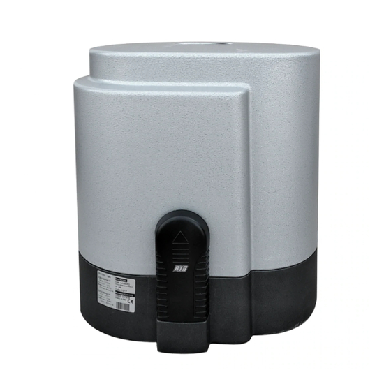
Irreversible operator for sliding gates
Hide thumbs
Also See for K800 Series:
- Manual (56 pages) ,
- Operating and installation instructions (37 pages) ,
- Simplified instructions (36 pages)
Table of Contents
Advertisement
Available languages
Available languages
K K 8 8 0 0 0 0 - - 1 1 4 4 0 0 0 0 - - 2 2 2 2 0 0 0 0
Operatore
Operateur
Operator
Torantrieb
Operador
K800
K800 PLUS
K1400
K1400 PLUS
K2200
K2200 PLUS
ITALIANO pag. 05 / FRANÇAIS pag. 15 / ENGLISH page 25 / DEUTCH pag. 35 / ESPAÑOL pag. 45
Alimentazione
con Encoder
Alimentation
avec Encoder
Power Supply
with Encoder
Stromspannung
mit Encoder
Alimentacion
con Encoder
230V 50/60Hz
120V 60Hz
230V 50/60Hz
120V 60Hz
230V 50/60Hz
120V 60Hz
230V 50/60Hz
120V 60Hz
230V 50/60Hz
120V 60Hz
230V 50/60Hz
120V 60Hz
OPERATORE IRREVERSIBILE PER CANCELLI SCORREVOLI
OPERATEUR IRREVERSIBLE POUR PORTAILS COULISSANTES
IRREVERSIBLE OPERATOR FOR SLIDING GATES
SELBSTHEMMENDER TORANTRIEB FÜR SCHIEBETOREN
OPERADOR IRREVERSIBLE PARA VERJAS CORREDERAS
Peso max cancello
Poids maxi portail
Max gate weight
Max Torgewicht
Peso máx verja
800Kg/1766lbs
X
800Kg/1766lbs
X
1400Kg/3090lbs
X
1400Kg/3090lbs
X
2200Kg/4856lbs
X
2200Kg/4856lbs
X
Spinta max
codice
Poussée maxi
Max Thrust
Max Schubkraft
Max Empuje
codigo
AA30039
60Kg/132lbs
AA30042
AA30014
60Kg/132lbs
AA30017
AA30044
64Kg/141lbs
AA30047
AA30019
64Kg/141lbs
AA30022
AA30049
115Kg/254lbs
AA30052
AA30024
115Kg/254lbs
AA30027
code
code
code
Advertisement
Table of Contents

Related Manuals for RIB K800 Series


Summary of Contents for RIB K800 Series
- Page 1 K K 8 8 0 0 0 0 - - 1 1 4 4 0 0 0 0 - - 2 2 2 2 0 0 0 0 OPERATORE IRREVERSIBILE PER CANCELLI SCORREVOLI OPERATEUR IRREVERSIBLE POUR PORTAILS COULISSANTES IRREVERSIBLE OPERATOR FOR SLIDING GATES SELBSTHEMMENDER TORANTRIEB FÜR SCHIEBETOREN OPERADOR IRREVERSIBLE PARA VERJAS CORREDERAS Operatore...
- Page 2 (ad esempio installandolo dentro quadro chiuso a chiave). être protégé contre toute remise en fonction accidentelle (ex. en 2° - Per la sezione ed il tipo dei cavi la RIB consiglia di utilizzare un l’installant dans un coffre fermant à clé).
- Page 3 Schluesselkatsten einem 2° - As far as the cable section and the cable kind are concerned, RIB Panzergehaeuse) suggests to use an H05RN-F cable, with a minimum section of 2° - RIB empfiehlt den Kabeltyp H05RN-F mit einem minimalen...
- Page 4 (por ejemplo instalándolo dentro de un panel cerrado a llave). 2° - Para la sección y el tipo de los cables, la RIB aconseja utilizar cables de tipo H05RN-F con sección mínima de 1,5mm igualmente atenerse a la norma IEC 364 y a las normas de instalación del propio País.
- Page 5 LAYOUT IMPIANTO 1 - Operatore K 2 - Fotocellule esterne 3 - Cremagliera Modulo 4 4 - Selettore a chiave 5 - Antenna radio 6 - Lampeggiatore 7 - Limitatori di corsa (camme) 8 - Costola meccanica 9 - Costola pneumatica o Fotocosta 10 - Fotocellule interne 11 - Colonnine per fotocellule 12 - Fermi meccanici...
- Page 6 INSTALLAZIONE K ONTROLLO PRE-INSTALLAZIONE - IL CANCELLO DEVE MUOVERSI SENZA ATTRITI - N.B. È obbligatorio uniformare le caratteristiche del cancello alle norme e leggi vigenti. Il cancello può essere automatizzato solo se in buono stato e se rispondente alla norma EN 12604. - L’anta non deve presentare porte pedonali.
- Page 7 ISSAGGIO MOTORE E CREMAGLIERA La cremagliera deve essere fissata a una certa altezza rispetto all’appoggio del motore. Questa altezza può essere variata grazie a delle asole presenti sulla cremagliera. La registrazione in altezza viene fatta affinché il cancello, durante il movimento, non si appoggi sull'ingranaggio di trazione del K (5 e 6).
- Page 8 COLLEGAMENTI ELETTRICI centralina KS cod. BC07050...
- Page 9 A - CONNESSIONI EXP. Connettore per scheda EXPANDER SEC.TRANSF. Connettore per secondario trasformatore L 1 - N Alimentazione 230 Vac 50/60 Hz (120V/60Hz a richiesta) PRI.TRANSF. Connettore per primario trasformatore NON TOCCARE IL PONTICELLO ! SE VIENE RIMOSSO L’OPERATORE NON FUNZIONA! SEC.LOCK Connettore per collegamento sicurezza sblocco manuale...
- Page 10 - B - - C - SETTAGGI CONTROLLO SENSO DI ROTAZIONE DEL MOTORE DIP 1 CONTROLLO SENSO DI ROTAZIONE DEL Questo controllo ha il compito di agevolare l’installatore durante la MOTORE (ON) (PUNTO C) messa in opera dell’impianto, o durante eventuali controlli successivi. DIP 2 PROGRAMMAZIONE TEMPI (ON) (PUNTO D) 1 - Dopo aver regolato le camme di finecorsa (fig.7), posizionare il cancello a metà...
- Page 11 In caso di mancato funzionamento dell’Encoder (non alimentato, fili UNZIONAMENTO ACCESSORI DI COMANDO staccati, disco rotto o difettoso) la movimentazione del cancello non viene eseguita. Se dopo l’intervento dell’Encoder in apertura o chiusura PULSANTE DI APERTURA (COM-OPEN) con funzione orologio si ha un secondo intervento dell’Encoder, ovviamente nel senso A cancello fermo il pulsante comanda il moto di apertura.
- Page 12 ARATTERISTICHE TECNICHE - Tutti gli ingressi devono essere utilizzati come contatti puliti perchè - Umidità < senza l’alimentazione è generata internamente (tensione sicura) alla scheda condensazione ed è disposta in modo da garantire il rispetto di isolamento doppio o - Tensione di alimentazione 230V~ ±10% (a richiesta 120V±10%) rinforzato rispetto alle parti a tensione pericolosa.
- Page 13 FUNZIONI PRINCIPALI COSTA IN APERTURA (11-12) Durante l’apertura, se impegnata, inverte il moto in chiusura anche se MONITORAGGIO DI QUATTRO FOTOCELLULE rimane impegnata. Durante la chiusura non é attiva. Se non usata, APERTURA PEDONALE ponticellare i morsetti 11-12. CHIUSURA AUTOMATICA PEDONALE NB: Dalla revisione SW.07 sulle schede KS e KS Super, questo GESTIONE COSTA IN APERTURA ingresso funziona nel seguente modo:...
- Page 14 PARK LOCK SELETTORE A CHIAVE DA PARETE cod. ACG1053 SELETTORE A CHIAVE DA INCASSO cod. ACG1048 Per ottenere le migliori prestazioni degli apparati sopracitati, bisogna installare un’antenna accordata sulla frequenza del radio ricevitore REMAGLIERA MOD. 4 IN NYLON installato . N.B.
- Page 15 SCHÉMA DÉTAILLÉ DE L’INSTALLATION 1 - Opérateur K 2 - Photocellules extérieures 3 - Crémaillère Module 4 4 - Sélecteur à clé 5 - Antenne radio 6 - Feu clignotant 7 - Limiteurs de course (cames) 8 - Nervure mécanique 9 - Nervure pneumatique ou "Photonervure"...
- Page 16 INSTALLATION K ONTRÔLE PRÉ-INSTALLATION !! LE PORTAIL DOIT SE DÉPLACER SANS FROTTER !! N.B. Il est impératif d'uniformiser les caractéristiques du portail avec les normes et les lois en vigueur. La portail peut être automatisée seulement si elle est en bon état et qu’elle est conforme à la norme EN 12604.
- Page 17 IXATION MOTEUR ET CRÉMAILLÈRE La crémaillère doit être fixée à une certaine hauteur par rapport au support du moteur. Cette hauteur peut être modifiée, grâce aux boutonnières présentes sur la crémaillère. Le réglage en hauteur est effectué afin que, lors du mouvement, le portail ne puisse appuyer sur l'engrenage de traction du K (5 et 6).
- Page 18 BRANCHEMENTS ÉLECTRIQUES coffret electronique KS cod. BC07050...
- Page 19 A - BRANCHEMENTS EXP. Connecteur pour carte EXPANDER SEC.TRANSF. Connecteur pour transformateur secondaire L 1 - N Alimentation 230 Vac 50/60 Hz (sur demande 120V/60Hz) PRI.TRANSF. Connecteur pour transformateur primaire NE TOUCHEZ PAS LE PONTET! S'IL EST ENLEVÉ, L'OPÉRATEUR NE SE DÉPLACE PAS! SEC.LOCK Connecteur pour branchement dispositif de sécurité...
- Page 20 - B - - C - AJUSTEZ MICROINTERRUPTEURS CONTRÔLE DU SENS DE ROTATION DU MOTEUR CONTROLE Ce contrôle a pour but de rendre plus aisée la tâche de l’installateur, DIP 1 CONTRÔLE DU SENS DE ROTATION DU lors de la mise en œuvre de l’installation ou pour tous éventuels MOTEUR (ON) (POINT C) contrôles successifs.
- Page 21 ONCTIONNEMENT DES ACCESSOIRES DE COMMANDE ONCTIONNEMENT DES ACCESSOIRES DE SÉCURITÉ POUSSOIR D'OUVERTURE (COM-OPEN) avec fonction horloge ENCODEUR DE SÉCURITÉ (KPLUS) A la capacité d'agir comme une sécurité aussi bien en ouverture Lorsque le portail est fermé, le poussoir commande le mouvement qu'en fermeture avec inversion du sens de marche en cas d'impact.
- Page 22 ouvert ou, quoi qu'il en soit, pas complètement fermé. Il ne s'éteint que lumineux avec résistance lorsque le portail est complètement fermé. Lors de la programmation, en série de 2,2 k ) cette signalisation n'est pas active. - Charge maximale à la sortie feu clignotant 40W avec charge résistive - Courant disponible pour photocellules et accessoires 0,4 A ±15% 24Vac N.B.: Si l'on excède avec les coffrets de commande ou avec les - Courant disponible sur connecteur radio...
- Page 23 FERMETURE AUTOMATIQUE PIÉTONNE Le monitorage permet un Test de Fonction des 4 couples de Les temps de pause précédant la fermeture automatique piétonne du photocellules et du cordon, exécuté à la fin de chaque ouverture portail sont enregistrés lors de la programmation. Le temps de pause complète du portail.
- Page 24 PARK LOCK BLOCK - SÉLECTEUR À CLÉ MURAL code ACG1053 BLOCK - SÉLECTEUR À CLÉ ENCASTRER code ACG1048 Afin d'optimaliser les performances des appareils suscités, il est indispensable d'installer une antenne accordée sur la fréquence du RÉMAILLÈRE MOD. 4 EN NYLON radiorécepteur installé.
- Page 25 SYSTEM LAY-OUT 1 - K operating device 2 - External photocells 3 - Rack of Module 4 4 - Key selector 5 - Radio antenna 6 - Blinker 7 - Limit switch plate (cams) 8 - Mechanical strip 9 - Pneumatic strip or Fotocosta K800 K1400 K2200...
- Page 26 INSTALLATION K HECKING BEFORE THE INSTALLATION !! THE GATE SHALL MOVE FRICTIONLESS !! N.B.: Gate features must be uniformed with the standards and laws in force. The door/gate can be automated only if it is in a good condition and its conditions comply with the EN 12604 norm. - The door/gate leaf does not have a pedestrian door.
- Page 27 OTOR AND RACK FITTING The rack shall be fitted over the motor support, at a certain distance from It. Its height can be adjusted thanks to the holes In the rack. The height adjusting is necessary to prevent the gate leaning on the driving gear (5 and 6).
- Page 28 ELECTRIC CONNECTIONS electric board KS code BC07050...
- Page 29 A - CONNEXIONS EXP. Header for EXPANDER card SEC.TRANSF. Header for secondary transformer L 1 - N Power supply 230 Vac 50/60 Hz (on request 120V/60Hz) terminal block PRI.TRANSF. Header for primary transformer DO NOT TOUCH THE JUMPER !IF IT IS REMOVED THE OPERATOR DOESN’T MOVE ! SEC.LOCK Connector to the manual release safety device...
- Page 30 - B - - C - SETTING MICROSWITCHES MOTOR DIRECTION CHECK DIP 1 MOTOR DIRECTION CHECK (ON) (POINT C) This control is carried out to facilitate the installation of the system or DIP 2 TIME PROGRAMMING (ON) (POINT D) any possible future control. 1 - After you have ensured the correct positioning of the limit OPERATING MICROSWITCHES switch plates, manually move the gate to half open position;...
- Page 31 PERATION OF THE OPERATING ACCESSORIES AFETY ACCESSORIES OPERATION OPENING BUTTON (COM-OPEN) with timer function SAFETY ENCODER (only for K PLUS) It must act as a security in opening and closing, with movement When the gate is standstill, the button operates the opening mode. If inversion in case of collision.
- Page 32 ECHNICAL DATA - All the inputs must be used as clear contacts because the power - Moisture < 95% without condensation supply is generated inside (safe power) the control panel, and it has - Power supply voltage 230V~ ±10% (on request been laid down in such a way to guarantee a double or strengthened 120V±10%) - Frequency...
- Page 33 MANAGEMENT IMMEDIATE CLOSING even if the safety edge remains pressed. During closing the safety edge is not active. When the safety edge is not in used, the contacts 11- PHOTOCELL2 INPUT 12 must be bridged. MANAGEMENT OF THE COURTESY LIGHT NB: from modification SW.07 on cards KS and KS Super, MANAGEMENT OF THE TRAFFIC LIGHT CONTROL operation of fence is as follows:...
- Page 34 PARK LOCK BLOCK KEY SELECTOR FOR WALL-INSTALLATION code ACG1053 BLOCK KEY SELECTOR TO BUILD-IN code ACG1048 In order to make the systems mentioned above give the best performances, you need to install an antenna tuned on the frequency of YLON RACK MODULE 4 the radio receiver installed.
- Page 35 ANLAGEN LAY-OUT 1 - Betriebsgerät K 2 - Externe Fotozellen 3 - Zahnstange Modul 4 4 - Schlüsselwählschalter 5 - Radioantenne 6 - Blinkleuchte 7 - Laufbegrenzer (Nocken) 8 - Mechanische Kontaktleisten 9 - Pneumatische Kontaktleisten oder Fotokontaktleiste 10 - Interne Fotozellen 11 - Standsäulen für Fotozellen 12 - Mechanische Anschläge ECHNISCHE EIGENSCHAFTEN...
- Page 36 INSTALLATION K OR DER MONTAGE AUSZUFÜHRENDE ÜBERPRÜFUNGEN !! DAS TOR MUSS REIBUNGSFREI LAUFEN !! ANMERKUNG: Es ist erforderlich, die Charakteristiken des Tors an die geltenden Normen und Gesetze anzupassen. Das Tor kann nur automatisch Angeschlossen werden, wenn es in einem einwandfreien Zustand ist und der EN12604 entspricht.
- Page 37 folgt von der Seite 39 OTORBEFESTIGUNG UND ZAHNSTANGE Die Zahnstange muss gegenüber der Motorhalterung in einer entsprechendenden Höhe befestigt werden. Diese Höhe kann mittels an der Zahnstange befestigten Ösen verändert werden. Die Höhenregulierung muss solange erfolgen, bis das Tor sich während der Bewegung nicht mehr auf das Zugrad K aufstützt (5, 6).
- Page 38 ELEKTROANSCHLÖÜSSE elektronische steuerung KS code BC07050...
- Page 39 A - VERBINDUNGEN EXP. Verbinder für Karte EXPANDER SEC.TRANSF. Verbinder für Zweittransformator L 1 - N Stromversorgung 230Vac 50/60 Hz (auf Antrag 120V/60Hz) PRI.TRANSF. Verbinder für Primärtransformator BERÜHREN SIE NICHT DEN JUMPER! WENN ER ENTFERNT WIRD, ZIEHT DER OPERATOR NICHT UM! SEC.LOCK Verbinder für...
- Page 40 - B - - C - DIE MIKROBEDIENUNGSSCHALTER EINSTELLEN KONTROLLE MOTOR-DREHRICHTUNG DIP 1 KONTROLLE MOTOR-DREHRICHTUNG (ON) Diese Kontrolle dient der Erleichterung der Installation während der (PUNKT C) Inbetriebnahme der Anlage oder der Ausführung von möglichen DIP 2 PROGRAMMIERUNG ZEITEN (ON) (PUNKT D) späteren Kontrollen.
- Page 41 zugelassen. UNKTIONSWEISE DES STEUERZUBEHÖRS Falls der Encoder-Betrieb nicht funktioniert (keine Stromversorgung, Kabel nicht verbunden, Scheibe beschädigt oder defekt), wird die ÖFFNUNGSTASTE (COM-OPEN) mit funktion uhr Torbewegung nicht ausgeführt. Diese Funktion ist in den Spitzenzeiten nützlich, wenn der Wenn nach dem Einsatz des Encoders beim Öffnen oder Schließen ein Fahrzeugverkehr sich verlangsamt (z.
- Page 42 ECHNISCHE EIGENSCHAFTEN - Alle Kontakte müssen frei von Verunreinigungen sein, und die - Feuchtigkeit < 95% ohne Kondensation Kabelanschlüsse müssen korrekt, und Ordnungsgemäß Isoliert und - Versorgungsspannung 230V~ ±10% (auf Antrag Angeschlossen sein. 120V±10%) - Frequenz 50/60 Hz - Die Elektronik führt selbständig nach jeder Veränderung der - Max.
- Page 43 Die Pausezeit ist mit dem DIP3 aktivierbar oder deaktivierbar (ON aktiv). erreicht hat. Nach jeder erfolgten Öffnung kann die Torschließung nur dann geschehen, SICHERHEITSKONTAKTE BEIM AUFFAHREN DES TORES (11-12) wenn die 4 Fotozellenpaare und die Rippe diese Überwachungskontrolle Wenn beim Auffahren des Tores der Sicherheitskontakt ausgelost wird, bleibt mit positivem Ergebnis durchgeführt haben.
- Page 44 PARK LOCK SCHLÜSSELWAHLSCHALTER BLOCK FÜR DIE WAND Kode ACG1053 SCHLÜSSELWAHLSCHALTER BLOCK ZUM EINBAU Kode ACG1048 Um die bestmöglichen Leistungen mit den o. g. Apparaten zu erhalten, muss eine auf die Frequenz des Funkempfängers abgestimmte YLON ZAHNRAD MOD. 4 Antenne montiert werden. Anmerkung: Besonders muss darauf geachtet werden, dass das Zentralkabel der Leitung nicht mit der externen Kupferumwicklung in Kontakt kommt, da dies die...
- Page 45 DISPOSICIÒN DE LA INSTALACIÒN 1 - Operador K 2 - Fotocélulas externas 3 - Cremallera Módulo 4 4 - Interruptor de llave 5 - Antena de radio 6 - Intermitente 7 - Limitadores de recorrido (leva) 8 - Nervadura mecánica 9 - Nervadura neumática o Fotonervadura 10 - Fotocélulas internas 11 - Columnas para las fotocélulas...
- Page 46 INSTALACIÓN K ONTROL PRE-INSTALACIÓN ¡¡LA VERJA TIENE QUE MOVERSE SIN ROCES!! Es obligatorio uniformar las características de la verja a las normas y leyes en vigor. La puerta puede ser automatizada sólo si se encuentra en buen estado y responde a la norma EN 12604. - La puerta no tiene que tener puertas peatonales.
- Page 47 NCLAJE MOTOR Y CREMALLERA La cremallera se tiene que anclar a una determinada altura respecto al soporte del motor. Dicha altura se puede variar gracias a unos ojales presentes en la cremallera. El ajuste de la altura se efectúa para que la verja durante el movimiento no se apoye sobre el engranaje de tracción del K (5,6).
- Page 48 CONEXIONES ELÉCTRICAS panel electronico KS cód. BC07052...
- Page 49 A - CONEXIÓN EXP. Conector para tarjeta EXPANDER SEC.TRANSF. Conector para secundario transformador L 1 - N Alimentación 230Vac 50/60Hzh (120V bajo requesta) PRI.TRANSF. Conector para primario transformador ¡NO TOCAR EL PUENTE! SI SE REMUEVE, EL MOTOR NO FUNCIONA! SEC.LOCK Conector para conexión...
- Page 50 - B - - C - CONFIGURAR LA CENTRAL REVISIÓN SENTIDO DEL MOTOR DIP 1TOCAR SOLAMENTE PARA CONTROLAR EL Este control tiene la función de facilitar la instalación o para eventuales SENTIDO DE ROTACIÓN DEL MOTOR (PUNTO controles sucesivos. 1 - Después de haber regulado los finales de carrera eléctricos, DIP 2TOCAR SOLAMENTE PARA PROGRAMAR LOS posicionar la cancela a mitad de carrera por medio del seguro TIEMPOS (PUNTO D)
- Page 51 FUNCIÓN RELOJ DE PULSADOR DE ABERTURA acciona otra vez el encoder, obviamente en el sentido opuesto, la verja se detiene e invierte por 1 segundo. La alarma acústica (buzzer) se Esta función es útil en las horas punta, cuando el tráfico de los vehículos está...
- Page 52 - Corriente disponible en el conector de radio 200mA 24Vac ARACTERÍSTICAS TÉCNICAS - Humedad < agua - Todas las entradas deben ser utilizadas como contactos limpios por condensación que la alimentación es generada del interior (tensión segura) al panel - Tensión de alimentación 230V~ ±10% de control y está...
- Page 53 El tiempo de pausa se puede activar y desactivar por medio de DIP 3 Después de cada abertura, se permite el cierre de la cancela solo si las (ON activado). 4 coplas de fotocélulas y la costa han superado el Test Funcional. FUNCIONES PRINCIPALES NERVADURA EN ABERTURA (11-12) Durante la abertura si se ha activado, invierte el movimiento de cierre...
- Page 54 PARK LOCK SELECTOR DE LLAVE DE PARED cód. ACG1053 SELECTOR DE LLAVE DE ENCAJAR cód. ACG1048 Para obtener las mejores prestaciones de los citados aparatos, es necesario instalar una antena sintonizada con la frecuencia del REMALLERA MOD. 4 DE NYLON radioreceptor.
- Page 55 R.I.B. S.r.l. 25014 Castenedolo - Brescia - Italy Via Matteotti, 162 Telefono ++39.030.2135811 Fax ++39.030.21358279 - 21358278 http://www.ribind.it - email: ribind@ribind.it DICHIARAZIONE DI CONFORMITÁ - DECLARATION OF COMPLIANCE DÉCLARATION DE CONFORMITÉ - ÜBEREINSTIMMNUGSERKLÄRUNG DECLARACIÓN DE CONFORMIDAD Dichiariamo sotto la nostra responsabilità che l’operatore K800-1400-2200 è conforme alle seguenti norme e Direttive: L’opérateur K800-1400-2200 se conforme aux normes suivantes: We declare under our responsibility that K800-1400-2200 operator is conform to the following standards: Wir erklaeren das der K800-1400-2200 den folgenden EN-Normen entspricht:...
- Page 56 K800-1400-2200 Questo prodotto è stato completamente progettato e costruito in Italia · Ce produit a été complètement développé et fabriqué en Italie · This product has been completely developed and built in Italy · Dieses Produkt wurde komplett in Italien entwickelt und hergestellt · Artìculo totalmente proyectado y producido en Italia B 05 10 40744 004 Codice...
Need help?
Do you have a question about the K800 Series and is the answer not in the manual?
Questions and answers