Table of Contents
Advertisement
Quick Links
Advertisement
Table of Contents

Related Manuals for Humandata LNX-003


Summary of Contents for Humandata LNX-003
- Page 1 RS-485/422 LAN Converter LNX-003(Rev2) User’s Manual Ver. 1.0 HuMANDATA LTD.
-
Page 3: Table Of Contents
8.5. Write or Read setting data over the network ............... 25 8.6. Setting Example ......................26 9. Virtual COM Port ......................28 10. Additional Documentation and User Support ............28 11. Attachment Documentations ..................28 12. Warranty and compensation..................28 LNX-003(Ver.1.0) -
Page 5: Precautions
Attention Item 7 notwithstanding, HuMANDATA cannot be held liable for the consequences arising from use of this product. HuMANDATA cannot be held liable for consequences arising from using this product in a way different from the uses described herein, or from uses not shown herein. -
Page 6: Revision History
Introduction Thank you for purchasing our product LAN to RS-485/422 Converter LNX-003. LNX-003 is a LAN converter which makes it possible to use RS-485/422 devices via Ethernet local area network. LNX-003 has obtained the CE marking.(except for PoE function) 1. -
Page 7: Product Summary
And by using TCP/UDP or Telnet, direct control from PC is also available. LNX-003 supports PoE function as a standard model, making it possible to be powered via LAN cable (PoE compatible HUB or other is required). It can also be operated from AC adapter. -
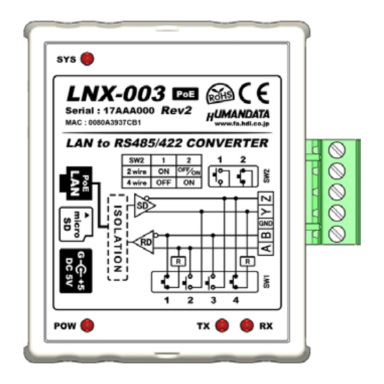
Page 8: Part Names And Functions
Card Slot LAN Side Active LED Power Input Link LED LEDs Name(color) Function Active LED (green) Turn on during network port communication. Turn on when LNX-003 is powered and LAN cable is LINK Link LED (yellow) connected normally. LNX-003(Ver.1.0) - Page 9 Blink few seconds during reading process. System LED (red) Turn on when system is ready. Power LED (red) Turn on when the power is supplied to the LNX-003. Transmission LED (red) Turn on when data are transmited to RS485/422 side. Reception LED (red) Turn on when data are received from RS485/422 side.
-
Page 10: Specifications
4. Specifications 4.1. Product Specification Item Description Remarks Model LNX-003 5VDC Supplied by AC adapter or LAN PoE function supports Power connector (PoE function) both mode A and B Current Consumption Less than 350mA IEEE802.3 (10Base-T) Network Interface IEEE802.3u (100Base-TX) half-duplex / full-duplex (auto detected) ESD protection ±11KV... -
Page 11: Ac Adapter
Storage Ambient Humidity 10 to 95 % RH Wire Length 1.6m Weight approx. 70 [g] 46 x 34 x 25 [mm] Dimensions Without projections 1.811" x 1.339" x 0.984" * There may be cases that this part and specifications are changed. LNX-003(Ver.1.0) -
Page 12: Optional Accessories
[CE marking] LNX-003 have applied the common standard for industrial environment EN61000-6-2 and EN61000-6-4. (except for PoE function) --- Application of the standards --- EMS: EN61000-6-2 · EN61000-4-2(2009) Electrostatic discharge requirements · EN61000-4-3(2010) Radiated electromagnetic field requirements · EN61000-4-4(2010) Electrical fast transient burst requirements ·... -
Page 13: Power Supply
4.4. Power Supply LNX-003 supports PoE function both A and B type as standard, making it possible to be powered via LAN cable (PoE compatible HUB is required). It also can be powered by the AC adapter. 4.5. RS-485/422 (4-wire) -
Page 14: Rs-485 (2-Wire)
RS-485 mode can communicate with multiple terminals by using a twist pair cable. 5. Interface Terminal Terminal block is detachable. Do not remove it while the power is supplied. Pin Number Signal Signal and Polarity The GND(Ground) pin is recommended to be wired. LNX-003(Ver.1.0) -
Page 15: Setting Switch
6. Setting Switch SW1 and SW2 can change the operating mode and echo cancelling. 6.1. RS-485/422 (4-wire) Mode Default Setting 4-wire * Please refer to Section 6.3 No termination Transmit Side termination Receive Side termination Both Sides termination LNX-003(Ver.1.0) -
Page 16: Rs-485 (2-Wire) Mode
No termination Termination Enable Disable the echo cancelling RS-485 6.3. Setting Switch (SW2) Function SW2-1 DE ( transmit enable) Control Always Enable Enable only Transmission SW2-2 Echo Control Echo Cancelling Enable (no echo) Echo Cancelling Disable (echo enable) LNX-003(Ver.1.0) -
Page 17: Connection Examples
RS-485/422 networks. By using cross cable, one to one connection is also available. [Tunneling mode between LNX-001 and LNX-003] LNX-001 offers you to control as USB interface via the LAN. By connecting this with LNX-003 in tunneling mode, virtual COM port and D2XX-API by FTDI is available. -
Page 18: Setting Tool
8. Setting Tool Setting tool supports data saving and reading using microSD card. This tool does not require installation. This is a screenshot from version 1.7 LNX-003(Ver.1.0) -
Page 19: Access Flow Of Microsd Card
LNX setting tool. Write setting data Saving backup data of RD_DATA.TXT in the micro SD card. TX/RX LED turn off Possible to remove of the microSD card SYS LED flicker (System start up) SYS LED turn on Ready LNX-003(Ver.1.0) -
Page 20: Function
Read or write setting data over the network. LNX product and PC Network must be connected to the same network segment. Product select Display product select window. Copy to clipboard Copy a display image to clipboard. Exit Terminate the application. LNX-003(Ver.1.0) - Page 21 The default setting is 10001. If you change the value, please avoid the following numbers. They are allocated to other function. 1-1024 Reserved for well-known ports Port number 9999 Reserved for telnet setup 14000-14009 Reserved for old redirector 30704 Reserved for remote control of user I/Os 30718 Reserved for configuration LNX-003(Ver.1.0)
- Page 22 Enter the remote port number for tunneling target. Connection method Select connection method to the target. LNX-003 and attached serial device must agree on a speed or baud rate to use for the serial connection.Valid baud rates are Baudrate 300, 600, 1200, 2400, 4800, 9600, 19200, 38400, 57600, 115200 or 230400.
- Page 23 After this idle gap time with no response from a serial device, data is packetized and transmitted to the target. The default setting is 12. Trigger character Select packet size and set trigger character (hexadecimal digits). Check sum Select check sum size. LNX-003(Ver.1.0)
- Page 24 Item Contents TCP keepalive time defines how many seconds LNX-003 waits during an inactive connection before checking its status. If the unit TCP keepalive does not receive a response, it drops that connection.Enter a value between 0 and 60 seconds. 0 disables keepalive.
-
Page 25: Write Setting Data
8.3. Write Setting Data 1. Open Setting Tool for LNX series (LNX SETTING TOOL Ver*.*). Select “LNX-003/LNX-003e LAN to RS485/422 Converter”, and click “OK”. 3. Enter the setting such as network or serial. 4. Insert a microSD card to PC (A USB adapter is included with the product) Click “Save data”. - Page 26 The start-up time can be shortened if the microSD card is removed from the product. Please be careful not to detach the microSD card before TX/RX LED is light off. LNX-003(Ver.1.0)
-
Page 27: Read Setting Data
* If there is the same file name in the microSD card, the data will be overwritten. 3. Insert a microSD card to PC (A USB adapter is included with the product) Start the setting tool and click “Reading data”. LNX-003(Ver.1.0) - Page 28 Click “OK” in the confirmation dialog. Open the “RD_DATA.TXT” in the microSD card. Setting data is loaded. LNX-003(Ver.1.0)
-
Page 29: Write Or Read Setting Data Over The Network
3. Click “Read data” or “Write data” * Even if some devices will be listed in the list and occur process time out. In this case, please change the PCs’ network setting to the same network segment as the product or using microSD card. LNX-003(Ver.1.0) -
Page 30: Setting Example
8.6. Setting Example [Tunneling mode between LNX-003] LNX-003 Side LNX-003 Side Network Setting 192.168.0.100 IP Address 192.168.0.101 255.255.255.0 Subnet Mask 255.255.255.0 0.0.0.0 Default Gateway 0.0.0.0 10005 Port Number 10005 Protocol 192.168.0.101 Remote IP Address 192.168.0.100 10005 Remote Port Number 10005... - Page 31 [LNX-003 single operation] LNX-003 Side Network Setting 192.168.0.100 IP Address 255.255.255.0 Subnet Mask 0.0.0.0 Default Gateway 10005 Port Number TCP Protocol 0.0.0.0 Remote IP Address 0 Remote Port Number Serial Communication 230400 Baudrate RTS/CTS (hard ware) Flow Control 1 Stop Bits...
-
Page 32: Virtual Com Port
Ethernet network using TCP/IP. LNX-003 attached to the network receives the data and transfers it from its own serial port to the attached equipment. Please refer to the "LNX series virtual COM port User's Manual"... - Page 33 LNX-003(Ver.1.0)
- Page 34 RS-485/422 LAN Converter LNX-003 Rev2 User’s Manual Ver. 1.0 ..........Oct. 25, 2016 HuMANDATA LTD. Address: 1-2-10-2F, Nakahozumi, Ibaraki Osaka, Japan ZIP 567-0034 Tel: 81-72-620-2002 (Japanese) Fax: 81-72-620-2003 (Japanese/English) URL: http://www.fa.hdl.co.jp (Japan) http://www.fa.hdl.co.jp/en(Global)
Need help?
Do you have a question about the LNX-003 and is the answer not in the manual?
Questions and answers