
Related Manuals for Leadshine Technology M542T


Summary of Contents for Leadshine Technology M542T
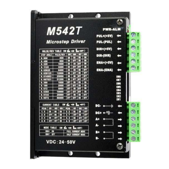
- Page 1 User's Manual M542T High Performance Microstepping Driver Version 1.0 .2011 All Rights Reserved Attention: Please read this manual carefully before using the driver!
-
Page 2: Operating Environment And Other Specifications
1. Introduction, Features and Applications Introduction The M542T is a high performance micro stepping driver based on pure-sinusoidal current control technology. Owing to the above technology and the self-adjustment technology (self-adjust current control parameters) according to different motors, the driven motors can run with smaller noise, lower heating, smoother movement and have better performances at higher speed than most of the drivers in the markets. -
Page 3: Pin Assignment And Description
3. Pin Assignment and Description The M542T has two connectors, connector P1 for control signals connections, and connector P2 for power and motor connections. The following tables are brief descriptions of the two connectors. More detailed descriptions of the pins and related issues are presented in section 4, 5, 9. -
Page 4: Connector P2 Configurations
4. Control Signal Connector (P1) Interface The M542T can accept differential and single-ended inputs (including open-collector and PNP output). The M542T has 3 optically isolated logic inputs which are located on connector P1 to accept line driver control signals. These inputs are isolated to minimize or eliminate electrical noises coupled onto the drive control signals. -
Page 5: Connecting The Motor
SepperOnline 5. Connecting the Motor The M542T can drive any 2-pahse and 4-pahse hybrid stepping motors. Connections to 4-lead Motors 4 lead motors are the least flexible but easiest to wire. Speed and torque will depend on winding inductance. In setting the driver output current, multiply the specified phase current by 1.4 to determine the peak output current. -
Page 6: Power Supply Selection
6. Power Supply Selection The M542T can match Large and small size stepping motors (from Nema size 17 to 34) made by NC-Tech or other motor manufactures around the world. To achieve good driving performances, it is important to select supply voltage and output current properly. -
Page 7: Selecting Microstep Resolution And Driver Output Current
Selecting Supply Voltage The power MOSFETS inside the M542T can actually operate within +24 ~ +100VDC, including power input fluctuation and back EMF voltage generated by motor coils during motor shaft deceleration. Higher supply voltage can increase motor torque at higher speeds, thus helpful for avoiding losing steps. -
Page 8: Wiring Notes
4.5A 3.2A Notes: Ref Current table on the screen printing is used for the users of the M542T to refer. Due to motor inductance, the actual current in the coil may be smaller than the dynamic current setting, particularly under high speed condition. - Page 9 M542T Microstepping Driver Manual V1.0 SepperOnline Remark: a) t1: ENA must be ahead of DIR by at least 5 s. Usually, ENA+ and ENA- are NC (not connected). See “Connector P1 Configurations” for more information. b) t2: DIR must be ahead of PUL effective edge by 5 s to ensure correct direction;...
Need help?
Do you have a question about the M542T and is the answer not in the manual?
Questions and answers