Advertisement
Quick Links
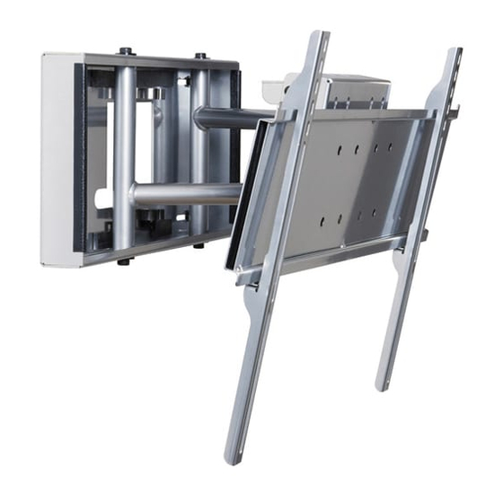
Installation and Assembly:
Pull-out Swivel Wall Mount with Universal Adapter
Bracket for 32" - 58" Flat Panel Screens
Models:
SP850-UNLP-GB, SP850-UNLP-GS, RTPS58I, RTPS58SI, RTPS58, RTPS58S
Maximum Load Capacity: 150 lb (68 kg)
3215 W. North Ave. • Melrose Park, IL 60160 • (800) 729-0307 or (708) 865-8870 • Fax: (708) 865-2941 • www.peerlessmounts.com
ISSUED: 11-21-06 SHEET #: 202-9183-6 05-12-08
Advertisement

Related Manuals for PEERLESS SP850-UNLP-GB


Summary of Contents for PEERLESS SP850-UNLP-GB
- Page 1 Bracket for 32" - 58" Flat Panel Screens Models: SP850-UNLP-GB, SP850-UNLP-GS, RTPS58I, RTPS58SI, RTPS58, RTPS58S Maximum Load Capacity: 150 lb (68 kg) 3215 W. North Ave. • Melrose Park, IL 60160 • (800) 729-0307 or (708) 865-8870 • Fax: (708) 865-2941 • www.peerlessmounts.com...
-
Page 2: Table Of Contents
NOTE: Read entire instruction sheet before you start installation and assembly. WARNING • Do not begin to install your Peerless product until you have read and understood the instructions and warnings contained in this installation sheet. If you have any questions regarding any of the instructions or warnings, please call Peerless customer care at 1-800-865-2112. -
Page 3: Parts List
RTPS58 RTPS58S SP850-UNLP-GB SP850-UNLP-GS RTPS58I RTPS58SI Parts List Black Silver Black Silver Description Qty. Part # Part # Part # Part # wall mount assembly 201-P1386 201-C4384 201-P1386 201-C4384 locking tab 200-P1871 200-C4871 200-P1871 200-C4871 .219 ID x .5 OD x .125H spacer... - Page 4 Phillips Adapter Bracket Fasteners M4 x 12 mm (6) M5 x 12 mm (4) M6 x 12 mm (4) 504-9013 520-1027 520-1128 M8 x 16 mm (6) M5 x 25 mm (4) M6 x 20 mm (4) 520-9257 520-9543 M4 x 25 mm (4) 520-9402 504-1015 I.D.
-
Page 5: Installation To Wood Stud Wall
Installation to Wood Stud Wall WARNING • Make sure that the supporting surface will safely support the combined load of the equipment and all attached hardware and components. Using a stud finder, locate the edges of the wood studs used in mounting this product. Use of an edge-to-edge stud finder is highly recommended. -
Page 6: Installation To Solid Concrete And Cinder Block
WARNING • When installing Peerless wall mounts on cinder block, verify that you have a minimum of 1-3/8" of actual concrete thickness in the hole to be used for the concrete anchors. Do not drill into mortar joints! Be sure to mount in a solid part of the block, generally 1"... - Page 7 Place installation tab over sliding arms of wall mount assembly (A) to lock them in place. INSTALLATION TAB SLIDING ARM 7 of 12 ISSUED: 11-21-06 SHEET #: 202-9183-6 05-12-08...
-
Page 8: Installing Adapter Plate
Installing Adapter Plate Thread two M10 x 15 mm screws (K), leaving .25" exposed thread, into top holes on back of adapter plate (EE). Hook adapter plate (EE) to mounting plate and attach using two bottom M10 x 15 mm screws (K) as shown in figures 4.1 and 4.2. -
Page 9: Installing Adapter Brackets
Installing Adapter Brackets WARNING • Tighten screws so adapter brackets are firmly attached. Do not tighten with excessive force. Overtightening can cause stress damage to screws, greatly reducing their holding power and possibly causing screw heads to become detached. Tighten to 40 in. • lb (4.5 N.M.) maximum torque. •... - Page 10 SCREW ADAPTER BRACKET (FF OR GG) If you have any questions, please call Peerless customer care at 1-800-865-2112. For Bump-out or Recessed Back Screen Refer to Screen Compatibility Chart to determine the proper fastener to use. Visit www.peerlessmounts.com/2 for a full screen compatibility chart for this mount.
-
Page 11: Mounting And Removing Flat Panel Screen
Mounting and Removing Flat Panel Screen WARNING • Always use an assistant or mechanical lifting equipment to safely lift and position the plasma television. Hook adapter brackets (FF or GG) onto adapter plate (EE), then slowly swing screen in as shown. Turn screws clockwise at least six times to prevent screen from being removed as shown in detail 1. - Page 12 SLIDING ARM CABLE MOUNT 12 of 12 ISSUED: 11-21-06 SHEET #: 202-9183-6 05-12-08 © 2008, Peerless Industries, Inc. All rights reserved. All other brand and product names are trademarks or registered trademarks of their respective owners.
Need help?
Do you have a question about the SP850-UNLP-GB and is the answer not in the manual?
Questions and answers