Table of Contents
Advertisement
Warnings............................................................................. . 18
Safety.instructions. . ............................................................. . 19
EC.Declaration.of.Conformity............................................. . 21
How.to.dismantle.SYSTEM.5000. . ...................................... . 22
Application.......................................................................... . 23
Technical.characteristics..................................................... . 23
Mounting./.installation. . ....................................................... . 23
Applications. . ....................................................................... . 24
Order................................................................................... . 25
Electrical.specifications. . ..................................................... . 25
Jumper.programming. . ........................................................ . 28
Function.description........................................................... . 29
Block.diagram.5202B1.and.5202B2. . ................................. . 30
Block.diagram.5202B4. . ...................................................... . 31
Connections........................................................................ . 32
Appendix:.
UL.Control.Drawing.No..5202QU01................................... . 65
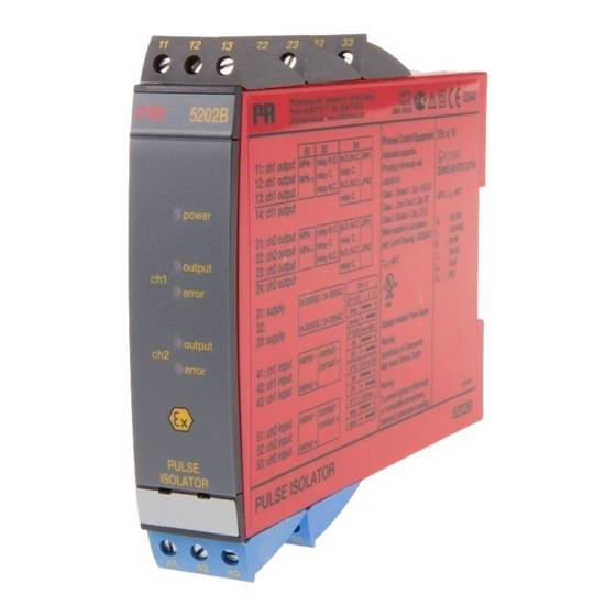
PULSE ISOLATOR
PRecon 5202B
Contents
17
Advertisement
Table of Contents

Related Manuals for PR electronics 5202B


Summary of Contents for PR electronics 5202B
-
Page 1: Table Of Contents
PULSE ISOLATOR PRecon 5202B Contents Warnings................18 Safety.instructions..............19 EC.Declaration.of.Conformity..........21 How.to.dismantle.SYSTEM.5000......... 22 Application................23 Technical.characteristics............23 Mounting./.installation............23 Applications................24 Order..................25 Electrical.specifications. -
Page 2: Warnings
Operators,.being.familiar.with.the.contents.of.this.manual,.adjust.and.operate. VOLTAGE General.mounting,.connection.and.disconnection.of.wires. the.knobs.or.potentiometers.during.normal.operation.. Troubleshooting.the.module. RECEIPT AND UNPACKING: Unpack.the.module.without.damaging.it.and.make.sure.that.the.manual.always. Repair of the module and replacement of circuit breakers follows.the.module.and.is.always.available..The.packing.should.always.follow. must be done by PR electronics A/S only. the.module.until.this.has.been.permanently.mounted.. Check.at.the.receipt.of.the.module.whether.the.type.corresponds.to.the.one. ordered.. WARNING ENVIRONMENT: 5202B4: Avoid.direct.sunlight,.dust,.high.temperatures,.mechanical.vibrations.and.shock,. To.keep.the.safety.distances,.one.relay.must.not.be.connected. as.well.as.rain.and.heavy.moisture..If.necessary,.heating.in.excess.of.the.stated. to.hazardous.voltage.at.the.same.time.as.the.other.relay.on.the. INSTAL- limits.for.ambient.temperatures.should.be.avoided.by.way.of.ventilation.. -
Page 3: Ec.declaration.of.conformity
As.manufacturer module... PR electronics A/S Should.there.be.any.doubt.as.to.the.correct.handling.of.the.module,.please. Lerbakken 10 contact.your.local.distributor.or,.alternatively,.. DK-8410 Rønde PR electronics A/S, Lerbakken 10, 8410 Rønde, Danmark tlf: +45 86 37 26 77. hereby.declares.that.the.following.product: Type: 5202B Mounting.and.connection.of.the.module.should.comply.with.national.legislation. Name: Pulse isolator for.mounting.of.electric.materials,.i.e..wire.cross.section,.protective.fuse,.and. is.in.conformity.with.the.following.directives.and. location..Descriptions.of.input./.output.and.supply.connections.are.shown.in. -
Page 4: How.to.dismantle.system.5000
HOW TO DISMANTLE SYSTEM 5000 PULSE ISOLATOR First, remember to demount the connectors with hazardous voltages. PRecon 5202B Picture 1: By.lifting.the.bottom.lock,.the.module. is.detached.from.the.DIN.rail.. • 2 channels - 2 or 4 outputs • 5-port 3.75 kVAC galvanic isolation • Dual output • Cable error detection •... -
Page 5: Electrical.specifications
NAMUR sensors Outputs Supply 1 NAMUR sensor 2 outputs Electrical specifications: Specifications range: Supply -20.to.+60°C Common specifications: Supply.voltage.universal....... 21.6...253.VAC 50...60.Hz. Contact with 19.2...300.VDC cable error detection Outputs Internal.consumption,.5202B1.and.5202B2... ≤.1.5.W.(2.channels) Max..consumption,.5202B1.and.5202B2..≤.1.5.W.(2.channels) Signal Internal.consumption,.5202B4....... ≤.2.0.W.(2.channels) Cable Max..consumption,.5202B4......≤.2.0.W.(2.channels) error Fuse............... 400.mA.T./.250.VAC Isolation.voltage,.test./.operation.... - Page 6 Inputs: GOST R approval: Sensor.types: VNIIM.&.VNIIFTRI,.Cert..no......See.www.prelectronics.com . NAMUR.acc..to......... EN.60947-5-6 Observed authority requirements: Standard: . Mechanical.contact.. EMC.2004/108/EC........EN.61326-1 Frequency.range........... 0...5.kHz LVD.2006/95/EC..........EN.61010-1 Pulse.length........... >.0.1.ms PELV/SELV............. IEC.364-4-41.and.EN.60742 Input.resistance..........1.kΩ ATEX.94/9/EC..........EN.50014,.EN.50020.and Trig.level,.signal.
-
Page 7: Jumper.programming
jumper programming: Function description: Examples.of.connections.on.block.diagram.(1)...(4) (1).NAMUR.sensor.with.cable.error.detection.in.case.of.cable.disconnection.or. short-circuit. (2).Mechanical.contact.with.cable.error.detection.in.case.of.cable.disconnection. or.short-circuit,.when.Rs.and.Rp.are.mounted.on.the.contact. (3).Mechanical.contact.with.cable.error.detection.in.case.of.cable.disconnection,. when.Rp.is.mounted.on.the.contact. (4).Mechanical.contact.without.cable.error.detection. •. When.a.channel.1.signal.or.cable.errors.are.transmitted.to.channel.2,.JP.22. must.be.in.position.2-3,.and.JP.23.must.be.in.position.1-2. •. Signal.transmission.to.channel.2:.If.the.channel.1.signal.is.inverted.(JP11.in. position.2-3),.the.channel.2.signal.will.also.be.inverted..In.this.case,.the.. inversion.on.channel.2.can.be.reversed.by.inverting.the.channel.2.signal. (JP21.in.position.2-3). •. When.channel.2.is.used.individually,.input.2.is.activated.by.JP.23.in.position. 2-3. -
Page 8: Block.diagram.5202B1.And.5202B2
BLOCK DIAGRAM: 5202B1 AND 5202B2 BLOCK DIAGRAM: 5202B4... -
Page 9: Connections
Connections: Supply: Inputs: NAMUR sensor Contact, cable error Contact, cable error Contact Ω Rp = 15 k Ω Rs = 750 to be mounted on contact NAMUR sensor Contact, cable error Contact, cable error Contact Ω Rp = 15 k Ω...
Need help?
Do you have a question about the 5202B and is the answer not in the manual?
Questions and answers