Table of Contents
Advertisement
Available languages
Available languages
Quick Links
Isolation
Galvanic isolators for analogue and digital
signals as well as HART
®
signals. A wide product range
with both loop-powered and universal isolators featuring
linearisation, inversion, and scaling of output signals.
Displays
Programmable displays with a wide se-
lection of inputs and outputs for display of temperature,
volume, weight, etc. Feature linearisation, scaling, and
difference measurement functions for programming via
PReset software.
Ex barriers
Interfaces for analogue and digital signals
as well as HART
®
signals between sensors / I/P convert-
ers / frequency signals and control systems in Ex zone 0,
1 & 2. Feature options such as mathematical functions
and 2 wire transmitter interfaces.
Temperature
A wide selection of transmitters for DIN
form B mounting and DIN rail modules with analogue
and digital bus communication ranging from application-
specifi c to universal transmitters.
Backplane
Flexible motherboard solutions for sys-
tem 5000 modules. Our backplane range features fl exible
8 and 16 module solutions with confi guration via PReplan
8470 – a PC program with drop-down menus.
5 2 0 2 B
P u l s e I s o l a t o r
N o . 5 2 0 2 B V 1 0 6 - I N ( 0 3 2 4 )
F r o m s e r . n o . 0 2 0 2 5 2 0 0 1
S I G N A L S T H E B E S T
Side 1
DK
Page 17
UK
Page 33
FR
Seite 49
DE
Advertisement
Chapters
Table of Contents

Related Manuals for PR electronics PRecon


Summary of Contents for PR electronics PRecon
- Page 1 Isolation Galvanic isolators for analogue and digital signals as well as HART ® signals. A wide product range with both loop-powered and universal isolators featuring linearisation, inversion, and scaling of output signals. Displays Programmable displays with a wide se- lection of inputs and outputs for display of temperature, volume, weight, etc.
-
Page 2: Table Of Contents
IMPULSISOLATOR PRecon 5202B Indholdsfortegnelse Advarsler ................Sikkerhedsregler..............Overensstemmelseserklæring ..........Adskillelse af SYSTEM 5000..........Anvendelse................. Teknisk karakteristik ............Montage / installation............Applikationer ..............Bestillingsskema..............Elektriske specifikationer ........... Jumperprogrammering............12 Funktionsbeskrivelse............13 Blokdiagram 5202B1 og -B2 ..........14 Blokdiagram 5202B4............15 Tilslutninger ................ 16... -
Page 3: Sikkerhedsregler
Reparation af modulet og udskiftning af sikringer må kun MODTAGELSE OG UDPAKNING: foretages af PR electronics A/S. Udpak modulet uden at beskadige dette, og sørg for, at manualen altid følger modulet og er tilgængelig. Indpakningen bør følge modulet, indtil dette er mon- teret på... -
Page 4: Overensstemmelseserklæring
PR electronics A/S den lokale forhandler eller alternativt direkte til: Lerbakken 10 PR electronics A/S, Lerbakken 10, 8410 Rønde, Danmark tlf: +45 86 37 26 77. Installation og tilslutning af modulet skal følge landets gældende regler for DK-8410 Rønde installation af elektrisk materiel bl.a. med hensyn til ledningstværsnit, for-sikring hermed at følgende produkt:... -
Page 5: Adskillelse Af System 5000
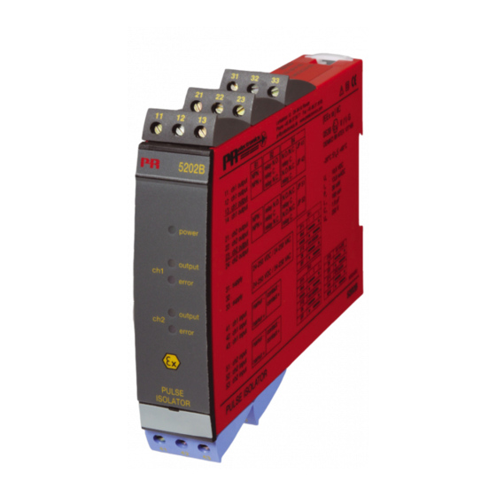
ADSKILLELSE AF SYSTEM 5000 IMPULSISOLATOR Husk først at demontere tilslutningsklemmerne med farlig spænding. PRecon 5202B Billede 1: Modulet frigøres fra DIN-skinnen ved at løfte i den nederste lås. • 2 kanaler - 2 eller 4 udgange • 5-port 3,75 kVAC galvanisk isolation •... -
Page 6: Elektriske Specifikationer
Elektriske specifikationer: Specifikationsområde: -20°C til +60°C Fælles specifikationer: Forsyningsspænding universel....24...230 VAC ±10% 50...60 Hz 24...250 VDC ±20% Egetforbrug, 5202B1 og -B2 ...... ≤ 1,5 W (2 kanaler) Max. forbrug, 5202B1 og -B2 ..... ≤ 1,5 W (2 kanaler) Egetforbrug, 5202B4 ........≤ 2,0 W (2 kanaler) Max. - Page 7 Indgange: Overholdte myndighedskrav: Standard: Følertyper: EMC 89/336/EØF, Emission ....... EN 50 081-1, EN 50 081-2 NAMUR i henhold til ....... EN 60 947-5-6 Immunitet...... EN 50 082-2, EN 50 082-1 Mekanisk kontakt Emission og immunitet...... EN 61 326 Frekvensområde.......... 0...5 kHz LVD 73/23/EØF..........
-
Page 8: Jumperprogrammering
Jumperprogrammering: Funktionsbeskrivelse: Forbindelseseksempler på blokdiagram (1)...(4) (1) NAMUR-føler med kabelfejlsdetektering for brud og kortslutning. (2) Mekanisk kontakt med kabelfejlsdetektering for brud og kortslutning, når Rs og Rp er monteret på kontakten. (3) Mekanisk kontakt med kabelfejlsdetektering for brud, når Rp er monteret på kontakten. -
Page 9: Blokdiagram 5202B1 Og -B2
BLOKDIAGRAM: 5202B1 OG -B2 BLOKDIAGRAM: 5202B4... - Page 10 PULSE ISOLATOR PRecon 5202B Contents Warnings ................18 Safety instructions.............. 19 Declaration of Conformity ..........21 How to dismantle SYSTEM 5000........22 Application ................. 23 Technical characteristics ............ 23 Mounting / installation............23 Applications................ 24 Order .................. 25 Electrical specifications............25 Jumper programming............
-
Page 11: Warnings
Repair of the module and replacement of circuit breakers the module until this has been permanently mounted. must be done by PR electronics A/S only. Check at the receipt of the module whether the type corresponds to the one ordered. -
Page 12: Declaration Of Conformity
Lerbakken 10 contact your local distributor or, alternatively, DK-8410 Rønde PR electronics A/S, Lerbakken 10, 8410 Rønde, Danmark tlf: +45 86 37 26 77. hereby declares that the following product: Mounting and connection of the module should comply with national legislation for mounting of electric materials, i.a. -
Page 13: How To Dismantle System 5000
HOW TO DISMANTLE SYSTEM 5000 PULSE ISOLATOR First, remember to demount the connectors with hazardous voltages. PRecon 5202B Picture 1: By lifting the bottom lock, the module is detached from the DIN rail. • 2 channels - 2 or 4 outputs •... -
Page 14: Electrical Specifications
Electrical specifications: Specifications range: -20 to +60°C Common specifications: Supply voltage universal ......24...230 VAC ±10% 50...60 Hz 24...250 VDC ±20% Internal consumption, 5202B1 and 5202B2 . ≤ 1.5 W (2 channels) Max. consumption, 5202B1 and 5202B2 ... ≤ 1.5 W (2 channels) Internal consumption, 5202B4 ..... - Page 15 Inputs: Observed authority requirements: Standard: Sensor types: EMC 89/336/EEC, Emission ....... EN 50 081-1, EN 50 081-2 NAMUR acc. to........EN 60 947-5-6 Immunity ....... EN 50 082-2, EN 50 082-1 Mechanical contact Emission and immunity ....... EN 61 326 Frequency range .........
-
Page 16: Jumper Programming
Jumper programming: Function description: Examples of connections on block diagram (1)...(4) (1) NAMUR sensor with cable error detection in case of cable disconnection or short-circuit. (2) Mechanical contact with cable error detection in case of cable disconnection or short-circuit, when Rs and Rp are mounted on the contact. (3) Mechanical contact with cable error detection in case of cable disconnection, when Rp is mounted on the contact. -
Page 17: Block Diagram 5202B1 And 5202B2
BLOCK DIAGRAM: 5202B1 AND 5202B2 BLOCK DIAGRAM: 5202B4... - Page 18 ISOLATEUR D’IMPULSIONS PRecon 5202B Sommaire Avertissements ..............34 Consignes de sécurité ............35 Déclaration de conformité..........37 Démontage du SYSTEME 5000......... 38 Application ................. 39 Caractéristiques techniques ..........39 Montage / installation............39 Applications................ 40 Référence de commande........... 41 Spécifications électriques ..........41 Programmation des cavaliers..........
-
Page 19: Avertissements
RECEPTION ET DEBALLAGE : Seule PR electronics SARL est autorisée à réparer le module Déballez le module sans l’endommager. Le guide doit toujours être disponible et et à remplacer les dis joncteurs. -
Page 20: Déclaration De Conformité
PR electronics SARL, Zac du Chêne, Activillage, 2, allée des Sorbiers, F- déclare que le produit suivant : 69500 Bron (tél. : (0) 472 140 607) ou à PR electronics A/S, Lerbakken 10, Type : 5202B DK-8410 Rønde, Danemark (tél. : +45 86 37 26 77). -
Page 21: Démontage Du Systeme 5000
DEMONTAGE DU SYSTEME 5000 ISOLATEUR D’IMPULSIONS Tout d’abord, n’oubliez pas de démonter les connecteurs où règnent des ten- PRecon 5202B sions dangereuses. Figure 1 : Débloquez le verrou inférieur pour dégager le module du rail DIN. • 2 voies - 2 ou 4 sorties •... -
Page 22: Spécifications Électriques
Spécifications électriques : Plage des spécifications : -20 à +60°C Spécifications communes : Tension d’alimentation universelle ....24...230 Vca ±10% 50...60 Hz 24...250 Vcc ±20% Consommation interne, 5202B1 et 5202B2.. ≤ 1,5 W (2 voies) Consommation max., 5202B1 et 5202B2... ≤ 1,5 W (2 voies) Consommation interne, 5202B4 .... - Page 23 Entrées : Agréments et homologations : Standard : Types de capteurs : CEM 89/336/CEE, Emission ....... EN 50 081-1, EN 50 081-2 NAMUR suivant ........EN 60 947-5-6 Immunité ....... EN 50 082-2, EN 50 082-1 Contact mécanique Emission et immunité ....... EN 61 326 Gamme de fréquences........
-
Page 24: Programmation Des Cavaliers
Programmation des cavaliers : Déscription des fonctions : Exemples de connexions du schéma de principe (1)...(4) : (1) Capteur NAMUR avec la détection de ruptures et court-circuits. (2) Contact mécanique avec la détection de ruptures et court-circuits, quand le Rs et le Rp sont montés sur le contact. (3) Contact mécanique avec la détection de ruptures, quand le Rp est monté... -
Page 25: Schéma De Principe 5202B1 Et 5202B2
SCHEMA DE PRINCIPE : 5202B1 ET 5202B2 SCHEMA DE PRINCIPE : 5202B4... - Page 26 IMPULSISOLATOR PRecon 5202B Inhaltsverzeichnis Warnung ................50 Sicherheitsregeln..............51 Konformitätserklärung............53 Zerlegung des Systems 5000 ..........54 Verwendung................ 55 Technische Merkmale............55 Montage / Installation............55 Anwendungen ..............56 Bestellangaben..............57 Elektrische Daten ............... 57 Überbrücker Programmierung ........... 60 Funktionsbeschreibung ............61 Blockdiagramm 5202B1 und 5202B2........
-
Page 27: Warnung
Reparaturen des Moduls und Austausch von Sicherungen EMPFANG UND AUSPACKEN: dürfen nur von PR electronics A/S vorgenommen werden. Packen Sie das Modul aus, ohne es zu beschädigen und sorgen Sie dafür, dass das Handbuch stets in der Nähe des Moduls und zugänglich ist. -
Page 28: Konformitätserklärung
DK-8410 Rønde direkt mit PR electronics GmbH, Bamlerstraße 92, D-45141 Essen, (Tel.: (0) 201 860 6660) oder mit PR electronics A/S, Lerbakken 10, DK-8410 Rønde, hiermit für das folgende Produkt: Dänemark (Tel. : +45 86 37 26 77) Kontakt aufnehmen. -
Page 29: Zerlegung Des Systems 5000
ZERLEGUNG DES SYSTEMS 5000 IMPULSISOLATOR Zunächst ist gefährliche Spannung von den Anschlussklemmen zu trennen. PRecon 5202B Abbildung 1: Das Modul wird von der DIN- Schiene gelöst, indem man den • 2-kanalig - 2 oder 4 Ausgänge unteren Verschluss löst. • 5-Port 3,75 kVAC galvanische Trennung •... -
Page 30: Elektrische Daten
Elektrische Daten: Spezifikationsbereich: -20 bis +60°C Allgemeine Daten: Versorgungsspannung universell ....24...230 VAC ±10% 50...60 Hz 24...250 VDC ±20% Eigenverbrauch, 5202B1 und 5202B2 ..≤ 1,5 W (2 Kanäle) Max. Verbrauch, 5202B1 und 5202B2..≤ 1,5 W (2 Kanäle) Eigenverbrauch, 5202B4......≤ 2,0 W (2 Kanäle) Max. - Page 31 Eingänge: Eingehaltene Behördenvorschriften: Norm: Sensortypen: EMV 89/336/EWG, Emission ...... EN 50 081-1, EN 50 081-2 NAMUR gemäß ........EN 60 947-5-6 Immunität ....EN 50 082-2, EN 50 082-1 Mechanischer Schalter Emission und Immunität ....EN 61 326 Frequenzbereich.......... 0...5 kHz LVD 73/23/EWG ..........
-
Page 32: Überbrücker Programmierung
Überbrücker Programmierung: Funktionsbeschreibung: Verbindungsbeispiele auf Blockdiagramm (1)...(4) (1) NAMUR-Sensor mit Kabelfehlererkennung für Bruch und Kurzschluss. (2) Mechanischer Schalter mit Kabelfehlererkennung für Bruch und Kurzschluss, wenn Rs und Rp auf dem Schalter montiert ist. (3) Mechanischer Schalter mit Kabelfehlererkennung für Bruch, wenn Rp auf dem Schalter montiert ist (4) Mechanischer Schalter ohne Kabelfehlererkennung. -
Page 33: Blockdiagramm 5202B1 Und 5202B2
BLOCKDIAGRAMM: 5202B1 UND 5202B2 BLOCKDIAGRAMM: 5202B4... - Page 35 Head offi ce PR electronics A/S tilbyder et bredt program af analoge og di- Denmark www.prelectronics.com gitale signalbehandlingsmoduler til industriel automation. Vores PR electronics A/S sales@prelectronics.dk Lerbakken 10 tel. +45 86 37 26 77 kompetenceområder omfatter: Isolation, Displays, Ex-barrierer, DK-8410 Rønde fax +45 86 37 30 85 Temperatur samt Backplanes.
Need help?
Do you have a question about the PRecon and is the answer not in the manual?
Questions and answers