Table of Contents
Advertisement
Available languages
Available languages
Advertisement
Chapters
Table of Contents

Subscribe to Our Youtube Channel
Related Manuals for Riello Burners Gulliver BLU Series


Summary of Contents for Riello Burners Gulliver BLU Series
- Page 1 Installation, use and maintenance instructions Montage und Bedienungsanleitung Light oil burners Öl-Gebläsebrenner One stage operation Einstufiger Betrieb CODE MODEL - MODELL TYPE - TYP 3737066 BGK1 370T1 3737456 BGK2 374T1 2903330 (3) - 10/2008...
- Page 2 DECLARATION OF CONFORMITY Royal Decree (A.R.) 8/1/2004 - Belgium Producer: RIELLO S.p.A. 37045 Legnago (VR) Italy Tel. ++39.0442630111 www.rielloburners.com Distributed by: RIELLO NV Ninovesteenweg 198 9320 Erembodegem Tel. (053) 769 030 Fax. (053) 789 440 e-mail. info@riello.be URL. www.riello.be This is to certify that the series of units specified below conforms to the model of the type described in the EC declaration of conformity, and is produced and distributed in conformity with the requirements laid down in Belgian Royal Decree (A.R.) dated 8 January 2004.
-
Page 3: Table Of Contents
INDEX BURNER DESCRIPTION........... . . Burner equipment . -
Page 4: Burner Description
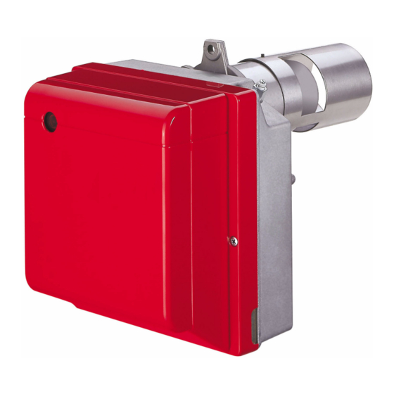
BURNER DESCRIPTION One stage light oil burner with low pollutant emissions (Nitric Oxide NOx, Carbon monoxide CO and unburnt Hydrocarbons). Burner with CE marking in conformity with EC directives: EMC 89/336/EC - 2004/108/EC, Low Voltage 73/23/EC - 2006/95/EC, Machines 98/37/EC and Efficiency 92/42/EC. CE Certification No.: 0036 0232/98 (370T1) –... -
Page 5: Technical Data
TECHNICAL DATA 2.1 TECHNICAL DATA TYPE 370 T1 374 T1 − − Output 3.0 kg/h 5.0 kg/h − − Thermal power 17.8 35.6 kW 59.3 kW Fuel Light oil, viscosity 4 – 6 mm /s at 20 °C ± Electrical supply Single phase, 230 V 50Hz Motor... -
Page 6: Installation
INSTALLATION THE BURNER MUST BE INSTALLED IN CONFORMITY WITH LEGISLATION AND LOCAL STANDARDS. WORKING POSITION The burner is designed for operation in positions 1 and 2 only. Installation 1 is the preferred option as it is the only one that enables maintenance to be performed as described later on in this manual. Operation is possible with installation option 2 though maintenance cannot be performed with the burner con- nected to the boiler. -
Page 7: Hydraulic Systems
HYDRAULIC SYSTEMS WARNING: Fig. 7 The burner is designed to accommodate the installation of light oil supply pipes on either side. It is necessary to install a filter on the fuel supply line. The pump is designed to allow working with two pipes. In order to obtain one pipe working it is necessary to unscrew the return plug (2), remove the by-pass screw (3) and then screw again the plug (2). -
Page 8: Electrical Wiring
ELECTRICAL WIRING ATTENTION: Do not swap neutral and phase over, follow the diagram shown carefully and carry out a good earth connection. The section of the conductors must be at least 1mm². (Unless requested otherwise by local standards and legislation). The electrical wiring carried out by the installer must be in compliance with the rules in force in the country. -
Page 9: Burner Operation
BURNER OPERATION WARNING QUALIFIED PERSONNEL WITH THE RIGHT INSTRUMENTS MUST HANDLE THE BURNER'S FIRST START-UP COMBUSTION ADJUSTMENT In conformity with Efficiency Directive 92/42/EEC the application of the burner on the boiler, adjustment and testing must be carried out observing the instruction manual of the boiler, including verification of the CO and concentration in the flue gases, their temperatures and the average temperature of the water in the boiler. -
Page 10: Maintenance Position
MAINTENANCE POSITION Before performing maintenance on the burner, it is best to disconnect the system’s power supply. ACCESSIBILITY TO THE NOZZLE, THE DIFFUSER DISC AND THE ELECTRODES IS MADE EASY IN 2 WAYS: Unscrew and remove the screw fastening it to Pull the wires (2) from the control box and the the flange to take the burner off the boiler. -
Page 11: Combustion Head Setting
COMBUSTION HEAD SETTING, (fig. 14) Fig. 14 Combustion head adjustment varies depending on burner delivery. To adjust, proceed as follows: Turn adjusting screw (2) clockwise or anticlockwise until the notch on the regulating rod (3) is lined up with the outer surface of the nozzle-holder assembly (1). In the example, the regulating rod (3) is set to setpoint 3. -
Page 12: Operating Programme
4.10 OPERATING PROGRAMME 4.10.1 NORMAL OPERATION WITH PREHEATING KEY TO LAY-OUT – Photoresistance – Ignition transformer – Thermostat enabling start-up after pre- heating LED – Reset button LED indicating operating status MV – Fan motor PH – Oil heater TL – Limit thermostat V1 –... -
Page 13: Lockout Due To Firing Failure
4.10.2 LOCKOUT DUE TO FIRING FAILURE KEY TO LAY-OUT – Photoresistance – Ignition transformer – Thermostat enabling start-up after pre- heating LED – Reset button LED indicating operating status MV – Fan motor PH – Oil heater TL – Limit thermostat Green+Yellow V1 –... -
Page 14: Lockout Types And Triggering Times In Case Of Burner Malfunction
COLOUR CODE OF CONTROL BOX RESET BUTTON LED Flashing Operating status LED colour codes speed Seconds Standby LED unlit Preheating Yellow Pre-purging Green Long pre-purging Green Transformer ignition Green + Yellow flashing Fast Regular flame Green + Yellow flashing Slow Post-purging Green + Yellow Recycle... -
Page 15: Additional Programmable Control Box Functions
4.11 ADDITIONAL PROGRAMMABLE CONTROL BOX FUNCTIONS 4.11.1 POST-VENTILATION FUNCTION (t6) Post-ventilation is a function that maintains air ventilation even after the burner is switched off. The burner switches off when the limit thermostat (TL) opens, cutting off the fuel supply to the valves. To use this function the reset button must be pressed when the limit thermostat is not switched over (burner switched off). -
Page 16: Maintenance
MAINTENANCE Disconnect the electric supply to the burner by switching off the main power switch and close the light oil shut-off valve before maintaining or checking the system. The burner requires scheduled maintenance that must be carried out by qualified personnel and in compliance with local legislation. -
Page 17: Faults / Solutions
SIGNAL PROBABLE CAUSE Loss of flame during operations: 7 pulses – poor burner regulation (insufficient gas); – oil valve faulty or dirty; – faulty or dirty. photoresistance Check and monitor oil heater (if fitted): 8 pulses – heater or control thermostat faulty. ATTENTION To reset the control box after the diagnostics display, press the lockout-reset button. -
Page 18: Operating Irregularities
FAULT POSSIBLE CAUSES SOLUTION The photoresistance is dirty. Clear it. The photoresistance is defective. Change it. The fibre optic is dirty. Clear it. Burner runs normal- The fibre optic is not in line with the ly in the prepurge hole of the diffuser disc-holder as- Check the line-up. -
Page 19: Safety Warnings
SAFETY WARNINGS The dimension of the boiler’s combustion chamber must respond to specific values, in order to guarantee a combustion with the lowest polluting emissions rate. The Technical Service Personnel will be glad to give you all the imformation for a correct matching of this burner to the boiler. - Page 20 KONFORMITÄTSERKLÄRUNG K.E. 8.1.2004 - Belgium Hergestellt von: RIELLO S.p.A. 37045 Legnago (VR) Italy Tel. ++39.0442630111 www.rielloburners.com In den Verkehr gebracht durch: RIELLO NV Ninovesteenweg 198 9320 Erembodegem Tel. (053) 769 030 Fax. (053) 789 440 e-mail. info@riello.be URL. www.riello.be Wir bestätigen hiermit, dass die nachstehende Geräteserie dem in der CE-Konformitätserklä- rung beschriebenen Baumuster entspricht und dass sie im Einklang mit den Anforderungen des K.E.
- Page 21 INHAL BESCHREIBUNG DES BRENNERS ..........Mitgeliefertes Zubehör .
-
Page 22: Beschreibung Des Brenners
BESCHREIBUNG DES BRENNERS Einstufiger Ölbrenner mit niedrigem Schadstoffausstoß (Stickoxyde NOx, Kohlenmonoxyd CO und unver- brannte Kohlenwasserstoffe CmHn). Brenner mit CE-Kennzeichnung gemäß der EG-Richtlinien: EMV 89/336/EG - 2004/108/EG, Niederspan- nungsrichtlinie 73/23/EG - 2006/95/EG, Maschinenrichtlinie 98/37/EG und Wirkungsgradrichtlinie 92/42/EG. CE - Reg. - Nr.: 0036 0232/98 (370T1) - 0036 0233/98 (374T1), nach 92/42/EWG. Der Brenner entspricht der Schutzart IP X0D (IP 40) gemäß... -
Page 23: Technische Merkmale
TECHNISCHE MERKMALE TECHNISCHE DATEN 370 T1 374 T1 ÷ ÷ Durchsatz 3,0 kg/h 5,0 kg/h ÷ ÷ Brennerleistung 17,8 35,6 kW 59,3 kW ÷ Brennstoff Heizöl-EL, Viskosität 4 6 mm /s bei 20°C ± Stromversorgung Einphasig, 230 V 50Hz Motor Stromaufnahme 0,8 A –... -
Page 24: Installation
INSTALLATION DIE INSTALLATION DES BRENNERS MUSS IN ÜBEREINSTIMMUNG MIT DEN ÖRTLICHEN GESETZEN UND VORSCHRIFTEN AUSGEFÜHRT WERDEN. BETRIEBSPOSITION Der Brenner ist ausschließlich für den Betrieb in den Positionen 1 und 2 vorbereitet. Die Position 1 ist vorzuziehen, da sie die einzige ist, die eine Durchführung der Wartung wie hier folgend in die- ser Anleitung beschrieben ermöglicht. -
Page 25: Ölversorgungsanlage
ÖLVERSORGUNGSANLAGE WICHTIGER HINWEIS: Der Brenner ist für den Einbau der Heizölversorgungsrohre Abb. 7 auf beiden Seiten vorgerüstet. In der Brennstoff–Ansaugleitung muß ein Filter eingebaut werden. Die Pumpe ist werksseitig für den Zweirohr-Betrieb einge- richtet. Wird ein Pumpen-Einrohrbetrieb für notwendig erachtet, so ist der Rücklauf-Schlauchleitungsstopfen (2) zu lösen und die By-Pass Schraube (3) zu entfernen. -
Page 26: Elektrisches Verdrahtungsschema
ELEKTRISCHES VERDRAHTUNGSSCHEMA ACHTUNG: Nullleiter nicht mit Phase austauschen; sich genau an das angegebene Schema halten und eine gute Erdung ausführen. Der Leiterquerschnitt muss mindestens 1 mm2 sein. (Außer im Falle anderslautender Angaben durch Normen und örtliche Gesetze). Die vom Installateur ausgeführten elektrischen Verbindungen müssen den lokalen Bestimmungen entsprechen. -
Page 27: Betrieb
BETRIEB ACHTIUNG DIE ERSTE ZÜNDUNG MUSS DURCH QUALIFIZIERTES PERSONAL, AUSGESTATTET MIT GEEIGNE- TER INSTRUMENTIERUNG, AUSGEFÜHRT WERDEN. EINSTELLUNG DER BRENNERLEISTUNG In Konformität mit der Wirkungsgradrichtlinie 92/42/EWG müssen die Anbringung des Brenners am Heizkessel, die Einstellung und die Inbetriebnahme unter Beachtung der Betriebsanleitung des Heizkessels ausgeführt wer- den, einschließlich Kontrolle der Konzentration von CO und CO in den Abgasen, der Abgastemperatur und der mittleren Kesseltemperatur. -
Page 28: Wartungsposition
WARTUNGSPOSITION Vor der Wartung des Brenners muss die Spannung zur Anlage abgeschaltet werden. DER ZUTRITT ZUR DÜSE, ZUR STAUSCHEIBE UND ZU DEN ELEKTRODEN KANN AUF ZWEI VER- SCHIEDENE WEISEN ERFOLGEN: Die Befestigungsmutter am Flansch losschrauben Die Drähte (2) vom Steuergerät herausziehen, und entfernen, um den Brenner vom Heizkessel zu den Photowiderstand (8) abnehmen und die Mut- lösen. -
Page 29: Flammkopfeinstellung
FLAMMKOPFEINSTELLUNG, (Abb. 14) Abb. 14 Die Flammkopfeinstellung ist je nach Brennerdurchsatz verschieden. Für seine Einstellung ist wie folgt vorzugehen: Die Stellschraube (2) im oder gegen den Uhrzeiger- sinn drehen, bis die auf den Stellbügel (3) geprägte Kerbe mit der Außenfläche des Düsenstocks (1) zu- sammenfällt. -
Page 30: Betriebsprogramm
4.10 BETRIEBSPROGRAMM 4.10.1 NORMALBETRIEB MIT VORWÄRMUNG LEGENDE – Photowiderstand – Zündtransformator – Freigabethermostat zum Anfahren nach Vorwärmung LED – Betriebsstatusanzeige über Entstö- rungstaste MV – Gebläsemotor PH – Heizölvorwärmer TL – Grenzthermostat V1 – Ölventil Langsamblinken von Grün + Gelb Grün Schnellblinken von Grün + Gelb Gelb... -
Page 31: Störabschaltung Wegen Nicht Erfolgter Zündung
4.10.2 STÖRABSCHALTUNG WEGEN NICHT ERFOLGTER ZÜNDUNG LEGENDE – Photowiderstand – Zündtransformator – Freigabethermostat zum Anfahren nach Vorwärmung LED – Betriebsstatusanzeige über Entstö- rungstaste MV – Gebläsemotor PH – Heizölvorwärmer TL – Grenzthermostat Grün+Gelb V1 – Ölventil Gelb Grün Vorhandensein eines Signals nicht verlangt D7232 Langsamblinken von Grün + Gelb Schnellblinken von Grün + Gelb... -
Page 32: Abschaltungstypiken Und Eingriffszeiten Im Fall Eines Defekts Des Brenners
FARBCODE DER LED AN DER ENTSTÖRUNGSTASTE DES STEUERGERÄTS Blinkgeschwin- Betriebsstatus LED-Farbcode digkeit Sekunden Wartezeit Led aus Vorwärmung Gelb Vorbelüftung Grün Lange Vorbelüftung Grün Transformatorzündung Blinken von Grün + Gelb Schnell Ordnungsgemäße Flamme Blinken von Grün + Gelb Langsam Nachbelüftung Grün + Gelb Erneuter Anlauf Blinken von Grün + Gelb Mittleres... -
Page 33: Programmierbare Zusatzfunktionen Des Steuergeräts
4.11 PROGRAMMIERBARE ZUSATZFUNKTIONEN DES STEUERGERÄTS 4.11.1 NACHBELÜFTUNGSFUNKTION (t6) Die Nachbelüftung ist eine Funktion, mit der die Belüftung auch nach dem Ausschalten des Brenners stattfindet. Das Ausschalten des Brenners erfolgt bei der Öffnung des Begrenzungsthermostaten (TL) mit folglicher Unter- brechung der Brennstoffzufuhr der Ventile. Um diese Funktion zu benutzen, muss die Entstörtaste betätigt wer- den, wenn der Begrenzungsthermostat (TL) nicht umgeschaltet ist (Brenner aus). -
Page 34: Wartung
WARTUNG Vor der Durchführung von Reinigungs- oder Kontrollarbeiten, die elektrische Versorgung zum Brenner durch Betätigung des Hauptschalters der Anlage abschalten und das Ölasabsperrventil schließen. Der Brenner bedarf regelmäßiger Wartung, die von autorisiertem Personal und in Übereinstimmung mit ört- lichen Gesetzen und Vorschriften ausgeführt werden muss. Die regelmäßige Wartung ist für den korrekten Betrieb des Brenners von grundlegender Wichtigkeit;... -
Page 35: Störungen / Abhilfe
SIGNAL MÖGLICHE URSACHE Erlöschen der Flamme während des Betriebs: 7 Blinken – Brenner nicht eingestellt; – Ölventil defekt oder schmutzig; – Photowiderstand defekt oder schmutzig. Überprüfung und Kontrolle des Ölvorwärmers (falls vorhanden): 8 Blinken – Vorwärmer oder Kontrollthermostat defekt. ACHTUNG Um das Steuergerät nach der Anzeige der Diagnostik rückzustellen, muss auf die Entstö- rungstaste gedrückt werden . -
Page 36: Betriebsstörungen
STÖRUNGEN MÖGLICHE URSACHE ABHILFE Austauschen. Verschmutzte oder defekte Düse. Luftdurchsatz nachregulieren. Luftdurchsatz fehlerhaft. Brennstoffdruck und -Durchsatz überprü- Pumpendruck nicht korrekt einge- Gelbe Flamme. fen und gemäß den Angaben dieser An- stellt. leitung einstellen. Reinigen. Luftzufuhröffnung verschmutzt. Reinigen. Kessel verschmutzt. Zündelektroden nicht in richtiger Gemäß... -
Page 37: Hinweise Und Sicherheit
HINWEISE UND SICHERHEIT Um bestmögliche Verbrennungs-Ergebnisse sowie niedrige Emissionswerte zu erzielen, muß die Brenn- kammer-Geometrie des Heizkessels für den Brenner geeignet sein. Deshalb ist es notwendig, vor Einsatz des Brenners Informationen bei einzuholen, um ein einwandfreies Funktionieren des Brenners zu gewährleisten. Dieser Brenner darf nur für den Einsatzzweck verwendet werden, für den er hergestellt wurde. - Page 40 RIELLO S.p.A. I-37045 Legnago (VR) Tel.: +39.0442.630111 http:// www.rielloburners.com Subject modifications - Änderungen vorbehalten!
Need help?
Do you have a question about the Gulliver BLU Series and is the answer not in the manual?
Questions and answers