Table of Contents
Advertisement
Quick Links
Model
Fuel Type
Minimum Supply Pressure
Manifold Pressure - High
Manifold Pressure - Low
Orifice Size -Altitude 0-4500 ft.
Minimum Input
Altitude 0-4500 ft. (0-1372m)
Maximum Input
Altitude 0-4500 ft. (0-1372m)
Vent Sizing
GAS INLET
5
7
"
8
195mm
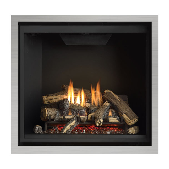
Grandview G800EC Gas Fireplace
G800EC-NG
G800EC-LP
Natural Gas
Propane
5" W.C. (1.25 kPa)
11" W.C. (2.73 kPa)
3.8" W.C. (0.94 kPa)
10.5" W.C. (2.62 kPa)
1.1" W.C. (0.27 kPa)
2.9" W.C. (0.72 kPa)
#42 DMS
#53 DMS
15,000 BTU/h
21,000 BTU/h
(4.54 kW)
(4.54 kW)
27,000 BTU/h
25,500 BTU/h
(8.33 kW)
(8.33 kW)
4" Inner / 6-5/8" Outer
4" Inner / 6-5/8" Outer
18"
457mm
OUTSIDE FINISH
CLEAN FRONT
4"
101mm
7
35
"
8
913mm
5
32
"
8
827mm
7
29
"
8
759mm
5
1
"
8
41mm
5
6
"
8
170mm
7
18
"
8
480mm
1
17
"
2
446mm
1
11
"
4
287mm
ELECTRICAL
INLET
1
7
"
2
192mm
1
11
"
4
287mm
Grandview® G800EC Gas Fireplace | P. 1
Advertisement
Table of Contents

Related Manuals for Regency Grandview G800EC Series


Summary of Contents for Regency Grandview G800EC Series
- Page 1 Grandview G800EC Gas Fireplace Model G800EC-NG G800EC-LP Fuel Type Natural Gas Propane Minimum Supply Pressure 5” W.C. (1.25 kPa) 11” W.C. (2.73 kPa) Manifold Pressure - High 3.8” W.C. (0.94 kPa) 10.5” W.C. (2.62 kPa) Manifold Pressure - Low 1.1” W.C. (0.27 kPa) 2.9”...
-
Page 2: Table Of Contents
G800EC Gas Fireplace Clearance / Framing and Venting Configurations The G800EC is designed to allow for unique installation options—depending on the desired finish. Please review the options and follow the specific clearance, framing, and finishing options for that application. The applications are as follows: Cool Wall application: combustible materials can be installed right up to the fireplace opening with this option. - Page 3 Cool Wall Install (Combustible Finishing) Cool Wall Install: • Vented chase • Combustible material can be used all around the fireplace • Combustible framing Clean Front Outside Finish w/ Finishing Trim Clean Front Standard Install (Non-Combustible Finishing) Standard Install: • Non-vented chase •...
-
Page 4: Cool Wall Clearances
Cool Wall Clearances The clearances listed below are minimum distances unless otherwise stated: A major cause of chimney related fires is failure to maintain required clearances (air space) to combustible materials. It is of the greatest importance that this fireplace and vent system be installed only in accordance with these instructions. WARNING Caution Requirements Fire hazard is an extreme risk... -
Page 5: Cool Wall Mantel Clearances
Cool Wall Mantel Clearances Due to the extreme heat this fireplace emits, the mantel clearances are critical. Combustible mantel clearances from top of front facing are shown in the diagram below. Mantel Clearances 14” Combustible 7” 2” Inches Top of Fireplace Opening To Floor... -
Page 6: Cool Wall Application-Framing
Cool Wall Application—Framing Framing Dimensions Description Cool Wall Cool Wall with Finishing Trim or Faceplate Framing Width 36-1/2" (927mm) 37-1/2" (952mm) Framing Height 43" (940mm) Framing Depth 16-7/8" (427mm) Corner Facing Wall Width 42-1/2" (1035mm) Corner Facing Wall Width 60" (1524mm) Framed Chase Ceiling Enclosure 80"... -
Page 7: Chase Vent Installation
Chase Vent Installation—Cool Wall G800EC Framed Opening must be at least 2 3/8” tall, and at least 33 3/8” wide to accomodate the Chase vent. The top of the Chase vent opening must be 1.5” or less from the top of the chase enclosure. Fasten the Chase vent with screws and construction adhesive. If the chase vent is not being used, a minimum 66in opening in the enclosure is required to maintain safe operating tempera- tures. -
Page 8: Clean Front Installation-Clearances
Clean Front Installation (non-Cool Wall)—Clearances The clearances listed below are minimum distances unless otherwise stated: A major cause of chimney related fires is failure to maintain required clearances (air space) to combustible materials. It is of the greatest importance that this fireplace and vent system be installed only in accordance with these instructions. WARNING Caution Requirements Fire hazard is an extreme risk... -
Page 9: Clean Front Installation Mantel Clearances
Clean Front Installation (non-Cool Wall)—Mantel Clearances Due to the extreme heat this fireplace emits, the mantel clearances are critical. Combustible mantel clearances from top of front facing are shown in the Diagram on the right. Note: Ensure the paint that is used on the mantel and the facing is "High Quality" or the paint may discolour. Mantel Clearances Combustible 19"... -
Page 10: Clean Front Installation-Mantel Leg Clearances
Clean Front Installation (non-Cool Wall)—Mantel Leg Clearances Allowable mantel leg projection TopView (38mm) Side opening 2" of fireplace 4-1/4" (51mm) (108mm) 1-1/2" 32-1/2" (826mm) (38mm) Overall Fireplace width 3" (76mm) 6-7/8" (175mm) Clean Front Installation (non-Cool Wall)—Non-Combustible Requirements: 37-1/2" [953mm] 11-1/2"... -
Page 11: Clean Front Installation-Framing (Non Cool Wall)
Clean Front Installation—Framing (non Cool Wall) Framing Dimensions Description G800EC - Non Cool Wall Framing Width 37-1/2"(953mm) Framing Height 43" (1092mm) O (Top Vent) Framing Depth - Top Vent 19-1/4" (489mm) P (Rear Vent) Corner Facing Wall Width 61-1/4" (1556mm) Q (Rear Vent) Corner Facing Wall Width 86-5/8"... -
Page 12: Clean Front Finishing
Clean Front Installation The finishing material can be brought to the edge of the fireplace opening. Do NOT finish beyond the opening, doing so will prevent the screen from being attached and removed. The Optional Clean Front Trim is available to prevent this from happening. See Section: C for details. -
Page 13: Outside Finish Installation-Clearances
Outside Finish Installation (non-Cool Wall)—Clearances The clearances listed below are minimum distances unless otherwise stated: A major cause of chimney related fires is failure to maintain required clearances (air space) to combustible materials. It is of the greatest importance that this fireplace and vent system be installed only in accordance with these instructions. WARNING Caution Requirements Fire hazard is an extreme risk... -
Page 14: Outside Finish Installation-Mantel Clearances
Outside Finish Installation (non-Cool Wall)—Mantel Clearances Due to the extreme heat this fireplace emits, the mantel clearances are critical. Combustible mantel clearances from top of front facing are shown in the Diagram below. Mantel Clearances Combustible 12" 7" 1" Non-Combustible Material Min. -
Page 15: Outside Finish Installation-Clearances
Outside Finish Installation (non-Cool Wall)—Framing Framing Dimensions Description Outside Finish Outside finish with Finishing Trim or Faceplate Framing Width 36-1/2" (927mm) 37-1/2" (953mm) Framing Height 43" (1092mm) Framing Depth 19-1/4" (489mm) Corner Facing Wall Width 46-1/2" (1181mm) Corner Facing Wall Width 65-3/4"... -
Page 16: Venting
Flex Vent or rigid pipe 4" x 6-5/8" The Diagrams show all allowable combinations of vent runs with 4" x 6-5/8" venting using the Regency direct vent system or rigid vent system. A vent guard should be used whenever the termination is lower than the specified minimum or as per local codes. -
Page 17: Rigid Pipe Venting Systems Horizontal Or Vertical Terminations
Rigid Pipe Venting Systems Horizontal or Vertical Terminations The minimum components required for a basic horizontal termination are: Horizontal Termination Cap Flat Wall Installation Elbow Wall Thickness (inches) Vent Length Required (inches) Rigid Pipe Adaptor Wall Thimble 4" - 5-1/2" 6"... - Page 18 Venting Arrangements - Horizontal Termination Rigid pipe and FPI direct vent system (flex) (Propane & Natural Gas) The diagram shows all allowable combinations of vertical runs with horizontal terminations, using one 90 elbow (two 45 elbows equal one 90 elbow). Note: Must use optional rigid pipe adaptor (Part # 510-994) when using Rigid Pipe venting systems.
- Page 19 Venting Arrangements Vertical Termination Rigid pipe system and vertical flex kit to same limitations (Propane & Natural Gas) The shaded area in the diagram shows all allowable combinations of straight vertical and offset to vertical terminations, using two 90 elbows, with rigid pipe vent systems for Propane and Natural Gas.
- Page 20 Horizontal terminations Two (2) 90°Elbows One 90 elbow = Two 45 elbows. Option H + H1 W i t h t h e s e o p t i o n s, maximum total pipe length 0' Min. 2' Max. is 30 feet with minimum of 6 feet total vertical 1' Min.
- Page 21 Vertical Venting with Two (2) 90 Elbows One 90 elbow = Two 45 elbows. Option V + V1 W i t h t h e s e o p t i o n s, maximum total pipe length 0' Min. 2' Max.
- Page 22 Vertical terminations Three (3) 90° Elbows (Rigid Pipe 4" x 6 - 5/8") One 90 elbow = Two 45 elbows. Option H + H1 V + V1 With these options, max. 0' Min. 2' Max. 2' Min. total pipe length is 30 feet 1' Min.
Need help?
Do you have a question about the Grandview G800EC Series and is the answer not in the manual?
Questions and answers