Advertisement
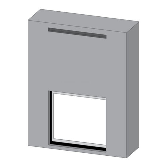
GRANDVIEW G1200P GAS FIREPLACE
MODEL
Fuel Type
Min. Supply Pressure
Manifold Pressure - High
Manifold Pressure - Low
Orifice Size - Altitude 0-4500 ft
Minimum Input Altitude 0-4500
ft. (0-1372m)
Maximum Input Altitude
0-4500 ft. (0-1372m)
CSA P.4.1
Fireplace Efficiency (FE)
Unit Dimensions
Lorem ipsum
GAS INLET
7
4
"
8
124mm
Minimum Fireplace Dimensions
Note: Gas connection is from the left hand side of the appliance & electrical connection on right hand side of the appliance. A metal receptacle box is supplied/
installed with the appliance to make all 120 volt electrical connections.
G1200P-NG
G1200P-LP
Natural Gas
5" W.C.
(1.25 kPa)
3.5" W.C.
(0.87 kPa)
1.6" W.C.
(0.39 kPa)
Left #46 DMS
Middle #45 DMS
Middle #56 DMS
Right #45 DMS
13,500 Btu/h
(3.96 kW)
53,000 Btu/h
(15.53 kW)
66.58%
1"
24mm
7
5
28
"
29
"
8
8
735mm
754mm
3
18
"
4
477mm
18"
458mm
3
44
"
3
4
32
"
8
37"
1136mm
822mm
941mm
FIREPLACE OPENING
5
3
1
4
"
MIN
"
14
"
8
4
4
119mm
20mm
361mm
7
43
16
1103mm
3
33
"
16
843mm
3-Sided Finishing Trim
Propane
11" W.C.
(2.74 kPa)
10" W.C.
(2.49 kPa)
6.4" W.C.
(1.60 kPa)
Left #56 DMS
Right #55 DMS
13,500 Btu/h
(3.96 kW)
53,000 Btu/h
(15.53 kW)
67.96%
41"
1042mm
202mm
126mm
1
27
"
2
698mm
55"
1396mm
3
41
"
4
1060mm
FIREPLACE OPENING
1
38
"
4
972mm
1
30
"
2
774mm
(4 x Leveling Legs)
6 5/8"
[168 mm]
"
34"
863mm
8"
5"
5 3/4"
[146 mm]
3
32
"
8
822mm
ELECTRICAL INLET
3
7
"
8
187mm
5"
128mm
8"
204mm
7
43
"
16
1103mm
4-Sided Finishing Trim
Grandview
G1200P Gas Fireplace |
®
1
1
45
"
3
44
"
2
42
"
8
4
1155mm
1121mm
1087mm
1
Advertisement
Table of Contents

Related Manuals for Regency GRANDVIEW G1200P


Summary of Contents for Regency GRANDVIEW G1200P
- Page 1 GRANDVIEW G1200P GAS FIREPLACE MODEL G1200P-NG G1200P-LP Fuel Type Natural Gas Propane 5” W.C. 11” W.C. Min. Supply Pressure (1.25 kPa) (2.74 kPa) 3.5” W.C. 10” W.C. Manifold Pressure - High (0.87 kPa) (2.49 kPa) 1.6” W.C. 6.4” W.C. Manifold Pressure - Low (0.39 kPa)
- Page 2 Cool Wall Installation (Combustible Finishing) Cool Wall Install: • Vented chase required • Combustible material can be used all around the fireplace • Combustible framing Note: Fan option is not permitted with Cool Wall Installation. Clean Front Non Cool Wall Installation (Non Combustible Finishing) Install: •...
- Page 3 Unit Assembly Prior to Installation (Nailing Flange Installation) - Cool Wall/Non Cool Wall IMPORTANT: The installation of the nailing flanges differ depending if this will be a cool wall or non cool wall installation. See following nailing flange installation instructions for both cool wall/non cool wall. Top Nailing Flange Left Nailing...
- Page 4 Non Cool Wall Nailing Flange Installation 1. Attach top and side nailing flanges using 6 screws provided in manual package. 2. Bend upper tabs inwards and rest these on unit top to set height. Attach sides to unit using 4 screws each. 3.
- Page 5 Cool Wall Clearances The clearances listed below are minimum distances unless otherwise stated. A major cause of chimney related fires is failure to maintain required clearances (air space) to combustible materials. It is of the greatest importance that this fireplace and vent system be installed only in accordance with these instructions. Caution Requirements WARNING Fire hazard is an extreme risk...
-
Page 6: Mantel Clearances
Cool Wall Mantel Clearances Due to the extreme heat this fireplace emits, the mantel clearances are critical. Combustible mantel clearances from top of front facing are shown in the diagram below. Mantel Clearances Combustible 12" 6" Inches Top of Fireplace Opening To Floor Mantel Clearances... - Page 7 Cool Wall Mantel Leg Clearances (Clean Front Finish) 3/4" (19 mm) 3/4" (19 mm) Mantel Leg Mantel Leg Side Opening Side Opening of Fireplace of Fireplace 12" (305 mm) 12" (305 mm) *42-1/4" (1073 mm) **41-3/4" (1060 mm) Overall Fireplace Width Allowable mantel leg projection Allowable mantel leg projection 9"...
- Page 8 Cool Wall Installation 2 x 4 or 2 x 6 - Framing NOTE: Framing may be constructed of combustible material (i.e. 2 x 4/2 x 6) and does not require steel studs. Framing Dimensions Description Cool Wall Framing Width 57-1/4" (1454 mm) Framing Height 51-1/4"...
-
Page 9: Maximum Tv Recess
• If you do place a television above the fireplace, please be aware of the amount of heat the fireplace generates. Regency in no way guarantees or takes responsibility for the suitability of the above installation for all homes, or any negative impacts from placing a TV above the fireplace, including damage to the TV. - Page 10 Cool Wall Installation - Cool Wall Conversion 4. Lift inner door and rotate tabs to lock it in place. Secure with the two 1. Remove four (4) screws shown. (2) screws removed in step 3. 2. Lift outer cover and secure with the 4 screws removed in step 1. 5 .
- Page 11 This can be achieved in a number of ways including the examples shown below. Warning: DO NOT cover or place objects in front of the air outlet(s). Minimum Opening Height of 2" (51 mm) Regency Chase Vent Custom chase vent Minimum Opening Height of 2" (51 mm)
- Page 12 Min 42.25” (1073 mm) Chase Enclosure (Cool Wall) Opening for vent When choosing to install the ventilation openings from the front, the top of the ventilation opening cannot be any lower than 1-1/2" (38mm) from the top of the chase enclosure for all installations. 4”-4.5”...
-
Page 13: Side View
G800EC G1200P Chase Vent Installation—Cool Wall (Part # 796 -991 Chase Vent White) CHASE VENT INSTALLATION—COOL WALL (PART #796-991 CHASE VENT WHITE) Framed Opening must be at least 3-5/8” tall, and at least 55-3/8” wide to accomodate the Chase vent. The top of the Chase vent opening must be 1-1/2”... - Page 14 Non Cool Wall - Clearances Non Cool Wall installation: Non-combustible required when installing materials right to the fireplace opening & no chase vent with this option. The clearances listed below are minimum distances unless otherwise stated: A major cause of chimney related fires is failure to maintain required clearances (air space) to combustible materials. It is of the greatest importance that this fireplace and vent system be installed only in accordance with these instructions.
- Page 15 Non Cool Wall - Mantel Clearances Due to the extreme heat this fireplace emits, the mantel clearances are critical. Combustible mantel clearances from top of front facing are shown in the Diagram on the right. Note: Ensure the paint that is used on the mantel and the facing is "High Quality" or the paint may discolour. Mantel Clearances Combustible Material 12"...
- Page 16 Non Cool Wall - Mantel Leg Clearances Combustible Non-combustible Non-combustible Combustible material material material material 3/4" (19 mm) 3/4" (19 mm) Mantel Leg Mantel Leg Side Opening Side Opening of Fireplace of Fireplace 12" (305 mm) 12" (305 mm) *42-1/4" (1073 mm) Overall Fireplace Width **41-3/4"...
- Page 17 Framing (Non Cool Wall) NOTE: Framing may be constructed of combustible material (i.e. 2 x 4/2 x 6) and does not require steel studs. Framing Dimensions Description G1200P - Non Cool Wall Framing Width 57-1/4" (1454 mm) Framing Height 60-1/4" (1530 mm) Framing Depth 29"...
- Page 18 Hearth Installation (Cool Wall/Non Cool Wall) Raised Hearth: If any combustible material extends above the bottom of the leveling legs, non combustible material such as tile, stone etc. must be used to act as a barrier. Combustible material cannot be exposed for the full width & depth of the hearth. See diagrams 1 & 3 Flush hearth /Finished Floor: Combustible Materials such material such as wood/vinyl flooring,linoleum, etc.
- Page 19 Finishing Material Installation - Cool Wall/Non Cool Wall The finishing material can be brought to the edge of the fireplace opening. Do NOT finish beyond the opening, doing so will prevent the screen or glass front from being attached and removed. IMPORTANT: Ensure that if this is a non cool wall application, only non combustible material is used.
- Page 20 Wall Board/Drywall/Non Combustible Board Installation G1200P (Cool Wall/Non Cool Wall) WARNING! Risk of Fire! Comply with all minimum clearances to combustibles as specified. Finishing Instructions: It is important to follow the framing and finishing instructions to ensure proper placement of fireplace into the surrounding framing/finishing materials. Wall board materials 1/2 in.
- Page 21 Cool Wall - Non Cool Wall Vent Pipe Clearances - Outside/Inside of Chase Enclosure This page notes all vent pipe clearances for both outside and inside of the chase enclosure. The clearances are different for both outside and inside of the chase enclosure and must be adhered to and is critical.
-
Page 22: Exterior Vent Termination Requirements
Exterior Vent Termination Requirements Minimum Clearance Requirements Canada Clearance above grade, veranda, porch, deck, or balcony 12"(30cm) 12"(30cm) Clearance to window or door that may be opened 12"(30cm) 9" (23cm) Clearance to permanently closed window Vertical clearance to ventilated soffit located above the terminal within a horizontal distance of 2 feet 29"(74cm) AstroCap/All Other 29"(74cm) AstroCap/All Other Approved Termination Caps... - Page 23 Intertek WHI listing of these components. The Regency AstroCap is certified for installations using Regency venting systems as well as any specific chimney systems listed in this manual. AstroCap is a proprietary trademark of Regency Fireplace Products.
- Page 24 Notes: 1) Liner sections should be continuous without any joints or seams. 2) Only Flex pipe purchased from Regency may be used for Flex installations. 3) Regency Direct Vent System (Flex) is only approved for horizontal terminations.
-
Page 25: Flat Wall Installation
Horizontal Terminations - Rigid Pipe 5" x 8" The minimum components required for a basic horizontal termination are: Horizontal Termination Cap Rigid Pipe Adaptor (770-994) Wall Thimble Length of pipe to suit wall thickness (see chart) AstroCap XL Horizontal (Part# 946-623/P) Termination Cap Wall thickness is measured from the back standoffs to the inside mounting surface of termination cap. - Page 26 Note : • Must use optional rigid pipe adapter (part# 770-994) when using rigid pipe venting systems. • For horizontal terminations, the Regency direct vent flex system may be used for installations with a maximum continuous vent length of up to 10 feet.
- Page 27 Lengths do not include elbow indicated. Must use rigid pipe adaptor #770-994 when using rigid venting. Note: For horizontal terminations the Regency Direct Vent Flex System may be used for installations up to a maximum continuous vent length of 10ft (3.0m). Grandview G1200P Gas Fireplace | ®...
- Page 28 Set 7 - 3 1/2" (89 mm) if required. For vertical terminations, the Regency Direct Vent Flex System may be used for installations with a maximum vent length of up to 40 feet including offsets.
- Page 29 Restrictor Set 3 If required for vertical terminations, the Regency Direct Vent Flex System may be used for installations with a maximum vent length of up to 40 feet including offsets. If longer runs are required, rigid pipe must be used. If no offsets are used, the maximum run is per the chart on this page.
- Page 30 Vertical Terminations - Three 90 Elbows (Rigid/Flex Pipe 5" x 8") for Both Natural Gas/Propane One 90 elbow = Two 45 elbows. Option V + V1 H + H1 W i t h t h e s e o p t i o n s , maximum total pipe length 2' Min.
Need help?
Do you have a question about the GRANDVIEW G1200P and is the answer not in the manual?
Questions and answers