Table of Contents
Advertisement
Quick Links
Greenfire
MODEL
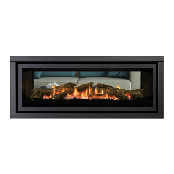
GF1500L NG-2
Fuel Type
Natural Gas
Gas Consumption
50 MJ/h
Manifold
0.87 kPa
Pressure
1 x #29
Injector Size
3.40 mm
GF1500L-2 Gas Fireplace
®
GF1500L LP-2
GF1500L ULPG-2
Propane
49 MJ/h
2.49 kPa
1 x #47
1.99 mm
633mm
1263mm
1151mm
ULPG
44 MJ/h
2.49 kPa
1 x #49
1.85 mm
560mm
523mm
Greenfire GF1500L-2 | 1
Advertisement
Table of Contents

Related Manuals for Regency Greenfire GF1500L NG-2


Summary of Contents for Regency Greenfire GF1500L NG-2
- Page 1 Greenfire GF1500L-2 Gas Fireplace ® MODEL GF1500L NG-2 GF1500L LP-2 GF1500L ULPG-2 Fuel Type Natural Gas Propane ULPG Gas Consumption 50 MJ/h 49 MJ/h 44 MJ/h Manifold 0.87 kPa 2.49 kPa 2.49 kPa Pressure 1 x #29 1 x #47 1 x #49 Injector Size 3.40 mm 1.99 mm 1.85 mm 633mm 560mm 1263mm 523mm 1151mm Greenfire GF1500L-2 | 1...
- Page 2 GF1500L-2 Gas Fireplace CLEARANCES The clearances listed below are minimum distances unless otherwise stated: A major cause of chimney related fires is failure to maintain required clearances (air space) to combustible materials. It is of the greatest importance that this fireplace and flue system be installed only in accordance with these instructions. WARNING Caution Requirements Fire hazard is an extreme risk...
- Page 3 GF1500L-2 Gas Fireplace FRAMING DIMENSIONS Framing IMPORTANT NOTE: Description GF1500 Dimensions This unit can be finished Framing Height 945 mm combustible finish with combustible facing ¹ Framing Height -Steel Stud 846 mm non combustible steel stud material of thickness range 10-19mm OR non-combus- Framing Width 1394 mm tible facing material of a Framing Depth 568 mm minimum thickness 12mm.
-
Page 4: Framing & Finishing (Combustible)
GF1500L-2 Gas Fireplace FRAMING & FINISHING (COMBUSTIBLE) Note: Finished *Finishing Trim or one of the fascias must be used with Material combustible finishing. 10mm to 19mm combustible finishing can be used if the 13mm 0mm-19mm thick- 1st slot air gap around the front facing of the unit is maintained. Finishing ness using combusti- material cannot be thicker than 19mm and must be flush with the ble finishing front edge of the flange. -
Page 5: Clearances For Combustible Finishing With Mantel
GF1500L-2 Gas Fireplace CLEARANCES FOR COMBUSTIBLE FINISHING WITH MANTEL Due to the extreme heat this fireplace emits, the mantel clearances are critical. Combustible finishing and mantel clearances are shown in the diagram on the right. Finishing Trim must be used with combustible finishing. Note: Maximum combustible finishing material thickness is (305mm) (152mm) 19mm measured from the front of the fireplace opening. If total finishing material is greater than 19mm, non- combustible must be used. -
Page 6: Non Combustible Mantel Leg Clearances
GF1500L-2 Gas Fireplace CLEARANCES FOR NON-COMBUSTIBLE FLUSH FINISHING WITH MANTEL Due to the extreme heat this fireplace emits, the mantel clearances are critical. Combustible mantel clearances from top of front facing are shown in the diagram on the right. Note: For a flushed finish using non-combustible finishing, (305 mm) (152 mm) seven 13mm stand-off tabs around the fireplace opening must be broken off. The top nailing flange cannot be used and a non-combustible steel stud must be installed to support (589mm) the non-combustible facing. -
Page 7: Flushed Finishing & Framing With Non-Combustible Material
GF1500L-2 Gas Fireplace FLUSHED FINISHING & FRAMING WITH NON-COMBUSTIBLE MATERIAL Note: For flush finishing, the top nailing strip must be removed and a Finished * diagrams shown below non-combustible steel stud support added. Material are with top nailing strip removed. The seven fireplace opening standoffs which are located on this unit can be removed when non combustible material is installed flush with the unit. 12mm (see P. 13). Non-combustible finishing material on the top and sides must also be used. MINIMUM THICKNESS OF THE FINISH MATERIAL: 12MM Unit 25mm Unit... -
Page 8: Optional Framing Kit
GF1500L-1 GF1500L-2 Gas Fireplace OPTIONAL FRAMING KIT OPTIONAL FRAMING KIT 1. Construct the timber framing, ensure inside dimensions are 1095 mm H x 1394 mm W as shown below. (607-065) Flat side out 5. Secure horizontal steel header stud (606-067) with 2 screws per side as 2. -
Page 9: Framing & Finishing (Clean Finish Installations Only)
GF1500L-2 Gas Fireplace FRAMING & FINISHING (CLEAN FINISH INSTALLATIONS ONLY) 1. Frame in the enclosure for the unit with framing material. IMPORTANT: The framed opening must be of non-combustible material. Note: When constructing the framed opening, please ensure there is access to install the gas lines when the unit is installed. -
Page 10: Flueing Introduction
GF1500L-2 Gas Fireplace FLUEING INTRODUCTION The GF1500L uses the "balanced flue" technology Co-Axial system. The inner liner vents products of combustion to the outside while the outer liner draws outside combustion air into the combustion chamber thereby eliminating the need to use heated room air for combustion and losing warm room air up the chimney. Note: These flue pipes must not be connected to any other appliance. The gas appliance and flue system must be vented directly to the outside of the building, and never be attached to a chimney serving a separate solid fuel or gas burning appliance. Each direct vent gas appliance must use it's own separate flue system. Common flue systems are prohibited. FLUEING ARRANGEMENT FOR HORIZONTAL TERMINATIONS The diagram shows all allowable combinations of vertical runs with horizontal terminations, using one 90 (two 45 elbows equal one 90 elbow). Note: Must use optional rigid pipe adapter (Part# 770-994) when using Simpson Dura Vent Only. Meters Restrictor Set #2 41 mm-open... - Page 11 GF1500L-2 Gas Fireplace FLUEING ARRANGEMENTS HORIZONTAL TERMINATION (FLEX) Regency Direct Vent System ® These flueing systems, in combination with GF1500L, have been tested and listed as a Direct Vent system by AGA. The location of the termination cap must conform to the requirements in the Flue Terminal Locations diagram from the "Exterior Flue Termination Locations" section. FPI Direct Vent (Flex) System Termination Kits include all the parts needed to install the GF1500L using a flexible vent. FPI Kit # Length Contains:...
- Page 12 GF1500L-2 Gas Fireplace RIGID PIPE FLUEING SYSTEMS BASIC HORIZONTAL & VERTICAL TERMINATIONS Rigid Pipe Flue Systems offer a complete line of component parts for installation of both horizontal and vertical installations. Many items are offered in decorative black, as well as galvanized finish. Vertical Terminal The minimum components required for a basic Horizontal Termination are: Flashing -Not Supplied AstroCap XL Termination Cap 90o Elbow Rigid Pipe Adaptor (Dura Vent Only) Wall Thimble Length of rigid pipe to suit wall thickness Pipe Length Flue Guard - if required Part 946-604/P The minimum components required for a basic (Part #946-506/P)
-
Page 13: Flueing Arrangement For Vertical Terminations
GF1500L-2 Gas Fireplace FLUEING ARRANGEMENT FOR VERTICAL TERMINATIONS Vertical Flue with Two (2) 90 Elbows (1 - 90 2 - 45 The shaded area in the diagram shows all allowable combinations of straight vertical and offset to vertical terminations, using two bends, with Rigid Pipe Flueing Systems. • Flue must be supported at offsets. • Maintain clearances to combustibles as listed in the "Clearances"... - Page 14 GF1500L-2 Gas Fireplace Vertical Venting with Three (3) 90 Elbows One 90 elbow = Two 45 elbows. H + H1 V + V1 With these options, tion max. total pipe 0 Min. 0.6 m Max. 0.6 m Min. length is 9.1 m with max. 2.4 m total 0.3 m Min. 0.6 m Max. 0.9 m Min. horizontal. 0.6 m Min.
Need help?
Do you have a question about the Greenfire GF1500L NG-2 and is the answer not in the manual?
Questions and answers