Regency Greenfire GF1500L Series Owners & Installation Manual
Hide thumbs
Also See for Greenfire GF1500L Series:
- Owners & installation manual (76 pages) ,
- Manual (15 pages) ,
- Owners & installation manual (72 pages)
Table of Contents
Advertisement
Quick Links
Greenfire
Gas Fireplace
www.regency-fire.com.au
WARNING:
If the information in these instructions are not followed
exactly, a fire or explosion may result causing property
damage, personal injury or loss of life.
FOR YOUR SAFETY
Do not store or use petrol or other flammable vapors and
liquids in the vicinity of this or any other appliance.
Installation and service must be performed by a qualified
installer, service agency or the gas supplier.
920-189
GF1500L
®
Installer: Please complete the details on the back cover
and leave this manual with the homeowner.
Homeowner: Please keep these instructions for future reference.
Owners &
Installation Manual
MODELS:
GF1500LNG-1
GF1500LLP-1
GF1500LULPG-1
LISTINGS AND CODE APPROVALS
These gas appliances have been tested in
accordance with AS/NZS 5263.0 & AS/NZS
5263.1.3/ and have been certified by the
Australian Gas Association for installation
and operation as described in these
Installation and Operating Instructions.
Must be installed as per AS/NZS 5601.
Your unit should be serviced annually by
an authorised service person.
FOR YOUR SAFETY
What to do if you smell gas:
Do not try to light any appliance.
Do not touch any electrical switch.
Do not use any phone in your
building.
Immediately call your gas supplier
from a neighbour's phone. Follow
the gas supplier's instructions.
If you cannot reach your gas
supplier, call the fire department.
06.05.20
Advertisement
Table of Contents

Related Manuals for Regency Greenfire GF1500L Series


Summary of Contents for Regency Greenfire GF1500L Series
- Page 1 Installation and Operating Instructions. Must be installed as per AS/NZS 5601. Your unit should be serviced annually by an authorised service person. www.regency-fire.com.au WARNING: FOR YOUR SAFETY If the information in these instructions are not followed What to do if you smell gas: exactly, a fire or explosion may result causing property Do not try to light any appliance.
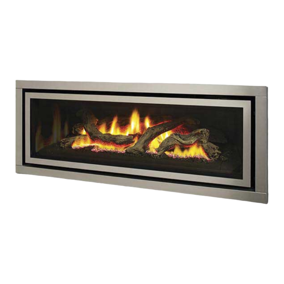
- Page 2 TO THE NEW OWNER Congratulations! You are the owner of a state-of-the-art Gas Fireplace by REGENCY . The GF1500L has been designed to provide you with ® all the warmth and charm of a wood fireplace at the flick of a switch. The model GF1500L has been approved by AGA for both safety and efficiency.
-
Page 3: Pairing The Remote Handset + Control Box Id Code
Note: The pairing process can be carried out by anyone. work – fan speed can be adjusted, flame height can be adjusted, etc. Note: Please visit www.regency-fire.com.au to see the pairing video. Fan Operation Note: To view a step-by-step pairing video please visit The fan must be on at all times while the unit is in operation. -
Page 4: Table Of Contents
table of contents Pairing the Remote Handset + Control Box ID Code ..3 Wiring Diagram (NG only) ...........33 Copy of data badge ............5 845 S.I.T. Valve Description .........33 Unit Dimensions ............6 Aeration Adjustment ............33 Conversion Kit from NG to Propane/ULPG ....34 Optional Fan Ducting Kit Installation ......35 INSTALLATION Optional Fan Kit Installation .........36... -
Page 5: Copy Of Data Badge
NOTE: Regency ® units are constantly being improved. Check the badge on the unit and if there is a difference, the badge on the unit is the correct one. COPY OF DATA BADGE Regency Gas Fireplace Distributed by: Model Western Australia:... -
Page 6: Unit Dimensions
dimensions UNIT DIMENSIONS 633mm 560mm 1263mm 523mm 1151mm Greenfield® G1500L Gas Fireplace... -
Page 7: Important Message
installation 11. Under no circumstances should this IMPORTANT MESSAGE YOUNG CHILDREN SHOULD BE appliance be modified. Parts that have to SAVE THESE INSTRUC- CAREFULLY SUPERVISED WHEN be removed for servicing should be replaced prior to operating this appliance. THEY ARE IN THE SAME AREA AS THE TIONS APPLIANCE. -
Page 8: Installation Checklist
installation INSTALLATION CHECKLIST This includes: 4. The GF1500L Direct Vent Gas Fireplace 1. Locate appliance 1. Clocking the appliance to ensure the correct is approved for alcove installations, see a) Room location (Refer to "Locating Your firing rate (noted on label) after burning "Clearances"... -
Page 9: Clearances
installation CLEARANCES The clearances listed below are Minimum distances unless otherwise stated: A major cause of chimney related fires is failure to maintain required clearances (air space) to combustible materials. It is of the greatest importance that this fireplace and flue system be installed only in accordance with these instructions. Caution Requirements WARNING The top, back and sides of the fireplace are defined... -
Page 10: Framing Dimensions
installation FRAMING DIMENSIONS IMPORTANT NOTE: Framing Description GF1500 This unit can be finished Dimensions with combustible facing Framing Height 945 mm combustible finish material of thickness range ¹ Framing Height -Steel Stud 846 mm non combustible steel stud 10-19mm OR non-combus- Framing Width 1394 mm tible facing material of a... -
Page 11: Combustible Finishing
installation COMBUSTIBLE FINISHING UNIT ASSEMBLY/ FINISHING/ MANTEL CLEARANCES + MANTEL LEG CLEARANCES UNIT ASSEMBLY PRIOR TO INSTALLATION The nailing strips must be correctly positioned and attached before unit is slid into position. NAILING STRIPS-COMBUSTIBLE FINISHING The nailing strips come attached to the unit. There is 1 plate on each side, 1 on the top. -
Page 12: Framing & Finishing (Combustible)
installation FRAMING & FINISHING (COMBUSTIBLE) Note: Finished *Finishing Trim or one of the fascias must be used with com- Material bustible finishing. 10mm to 19mm combustible finishing can be used if the 13mm 1st slot 0mm-19mm thick- air gap around the front facing of the unit is maintained. Finishing ness using combus- material cannot be thicker than 19mm and must be flush with the tible finishing... -
Page 13: Clearances For Combustible Finishing With Mantel
installation CLEARANCES FOR COMBUSTIBLE FINISHING WITH MANTEL Due to the extreme heat this fireplace emits, the mantel clearances are critical. Combustible finishing and mantel clearances are shown in the diagram on the right. Finishing Trim must be used with combustible finishing. Note: Maximum combustible finishing material thickness is 19mm (305mm) (152mm) -
Page 14: Non Combustible Flushed Finishing
installation NON COMBUSTIBLE FLUSH FINISHING UNIT ASSEMBLY/ FINISHING/ MANTEL CLEARANCES + MANTEL LEG CLEARANCES REMOVE TOP NAILING STRIPS & STANDOFFS AT SIDE AND UNDERNEATH Remove the top nailing strip/standoff by removing 4 screws in locations shown in Diagram to the right, then lift off and recycle. Break off the 8 standoffs with a pair of pliers. -
Page 15: Clearances For Non Combustible Flushed Finishing With Mantel
installation CLEARANCES FOR NON-COMBUSTIBLE FLUSH FINISHING WITH MANTEL Due to the extreme heat this fireplace emits, the mantel clearances are critical. Combustible mantel clearances from top of front facing are shown in the diagram on the right. Note: For a flushed finish using non-combustible finishing, seven (305 mm) (152 mm) 13mm stand-off tabs around the fireplace opening must be broken... -
Page 16: Flushed Finishing & Framing With Non-Combustible Material
installation FLUSHED FINISHING & FRAMING WITH NON-COMBUSTIBLE MATERIAL Note: For flush finishing, the top nailing strip must be removed and a non- * diagrams shown below are Finished combustible steel stud support added. with top nailing strip removed. Material The seven fireplace opening standoffs which are located on this unit can be removed when non combustible material is installed flush with the unit. -
Page 17: Installing A Tv/Artwork Flush With The Unit
installation INSTALLING A TV / ARTWORK FLUSH WITH THE UNIT Note: All wiring should stay free and clear of the vent system to avoid damage due to heat, if located directly in front of the vent system. Ensure wiring is secured without any sag. Heat deflector must overhang front of TV by 51mm. -
Page 18: Optional Framing Kit
installation GF1500L-1 OPTIONAL FRAMING KIT OPTIONAL FRAMING KIT 1. Construct the timber framing, ensure inside dimensions are 1095 mm H x 1394 mm W as shown below. (607-065) Flat side out 5. Secure horizontal steel header stud (606-067) with 2 screws per side as 2. -
Page 19: Non Combustible Facing Installation
The finishing of the walls or damage to board. The non combustible board must be surrounding Regency is as critical as the installation itself. The tem- a minimum of 12mm thick and comply with AS1530-1 and peratures around linear gas fireplaces are typically higher than would AS1530-3. -
Page 20: Framing & Finishing (Clean Finish Installations Only)
installation FRAMING & FINISHING (CLEAN FINISH INSTALLATIONS ONLY) 1. Frame in the enclosure for the unit with framing material. IMPORTANT: The framed opening must be of non-combus- tible material. Note: When constructing the framed opening, please ensure there is access to install the gas lines when the unit is installed. -
Page 21: Exterior Flue Termination Locations
installation EXTERIOR FLUE TERMINATION LOCATIONS FIGURE 6.2 (in part): LOCATION OF FLUE TERMINALS OF BALANCED FLUE AS/NZ 5601, ROOM-SEALED, FAN ASSISTED, OR OUTDOOR APPLIANCE Greenfield® G1500L Gas Fireplace... -
Page 22: Clearances
installation CLEARANCES Minimum clearances (mm) Ref. Item Natural Draught Assisted Below eaves, balconies and other projections: Appliances up to 50 MJ/h input Appliances up to 50 MJ/h input From the ground, above a balcony or other surface* From a return wall or external corner* From a gas meter (M) (see Note 5) (see Clause 5.11, 5.9 for vent terminal location of regulator) 1000... -
Page 23: Flue Restrictor Settings
installation FLUE RESTRICTOR SETTINGS Flue restriction is required for certain venting installations, see the diagrams in the "Flueing Arrangements" section to determine if they are required for your installation. The Flue Restrictor plate is located on the inside top of the firebox. To set the flue restriction as indicated in the flueing arrangements Set 3-(32mm) diagrams, refer to the following instructions;... -
Page 24: Flueing Introduction
installation FLUEING INTRODUCTION The GF1500L uses the "balanced flue" technology Co-Axial system. The inner liner vents products of combustion to the outside while the outer liner draws outside combustion air into the combustion chamber thereby eliminating the need to use heated room air for combustion and losing warm room air up the chimney. -
Page 25: Flueing Arrangements
FLUEING ARRANGEMENTS HORIZONTAL TERMINATION (FLEX) Regency Direct Vent System ® These flueing systems, in combination with GF1500L, have been tested and listed as a Direct Vent system by AGA. The location of the termination cap must conform to the requirements in the Flue Terminal Locations diagram from the "Exterior Flue Termination Locations" section. -
Page 26: Rigid Pipe Flueing Systems
installation RIGID PIPE FLUEING SYSTEMS BASIC HORIZONTAL & VERTICAL TERMINATIONS Rigid Pipe Flue Systems offer a complete line of component parts for installation of both horizontal and vertical installations. Many items are offered in decorative black, as well as galvanized finish. Vertical Terminal The minimum components required for a basic Horizontal Termination are:... -
Page 27: Flueing Arrangement For Vertical Terminations
installation FLUEING ARRANGEMENT FOR VERTICAL TERMINATIONS Vertical Flue with One(1) 90 Elbows (1 - 90 2 - 45 The shaded area in the diagram shows all allowable combinations of straight vertical and offset to vertical terminations, using two bends, with Rigid Pipe Flueing Systems. •... -
Page 28: Direct Flue Zero Clearance Top Exit Vertical Flue Kit Installation Instructions Gf1500L
installation DIRECT FLUE ZERO CLEARANCE TOP EXIT VERTICAL FLUE KIT INSTALLATION INSTRUCTIONS GF1500L This flue kit has been manufactured for use with GF1500L and to be installed in accordance with AS/NZS 5601. To ensure safety and correct unit operation this flue kit must be installed as outlined in these instructions. -
Page 29: Unit Installation With Horizontal Termination
installation UNIT INSTALLATION WITH 7. Ensure that the pipe clearances to combustible materials are maintained (Diagram 3). Install the HORIZONTAL TERMINATION termination cap. (Rigid Flue Systems) The four wood screws provided should be A top clearance of 76mm and side & bottom replaced with appropriate fasteners for stucco, clearance of 51mm must be maintained;... -
Page 30: Unit Installation With Vertical Termination
installation Note: For best results and optimum performance UNIT INSTALLATION WITH A poor draft, or down drafting can result from with each approved flueing system, high wind conditions near big trees or adjoining VERTICAL TERMINATION “Mill-Pac” sealant to every inner pipe roof lines, in these cases, increasing the flue (Rigid Systems) connection. -
Page 31: Unit Installation With Horizontal Termination Flex System
installation NOTE: Horizontal sections must be sup- UNIT INSTALLATION 8. Do the same with the 203mm liner. ported at intervals not exceeding (With Horizontal Termination Flex 0.9 meter. (Flame picture and per- 9. Apply a bead of silicone between the thimble System) formance will be affected by sags and termination and around the outer edge... -
Page 32: System Data
GF1500LLP-1 SYSTEM DATA Ignitor Pilot Electric Note: If you have an incorrect flame pattern, Min. Supply Pressure 2.75 kPa Modulator contact your Regency dealer for further ® Low Setting Man. 1.6 kPa instructions. Pressure Incorrect flame pattern will have small, probably Max. -
Page 33: Wiring Diagram (Ng Only)
installation WIRING DIAGRAM (NG ONLY) DISCONNECT POWER SUPPLY TO UNIT PRIOR TO WORKING ON ELECTRICAL COMPONENTS. 240 v a.c., 50 Hz, 0.8 A. 909-404 Caution: Ensure that the wires do not touch any CAUTION: Label all wires prior to disconnection hot surfaces and are away from sharp edges. -
Page 34: Conversion Kit From Ng To Propane/Ulpg
installation GF1500L-1 CONVERSION KIT FROM NG TO PROPANE/ULPG FOR GF1500L USING SIT 845 NOVA GAS VALVE CONVERSION KIT FROM NG TO PROPANE/ULPG REFER TO INSTRUCTIONS PROVIDED WITH CONVERSION KIT FOR MOST UP TO DATE INSTRUCTIONS. FOR GF1500L-1 PART #607-967 USING SIT 845 NOVA GAS VALVE THIS CONVERSION MUST BE DONE BY A QUALIFIED GAS FITTER IF IN DOUBT DO NOT DO THIS CONVERSION !! Each Kit contains one Propane / ULPG... - Page 35 GF1500L-1 installation 11. Reinstall new burner orifice Propane/ULPG and tighten. Burner Orifice #47 (Propane) When installing to gal Tee do NOT tighten from this point Burner Orifice # 49 (ULPG) 12. Adjust air shutter to fully open for both propane/ULPG. 13.
- Page 36 GF1500L-1 installation Minimum pressure: Remove one of the orange cables connected to the 28. At the end of all setting and adjustment operations, check elec- electric modulator. While holding the nut (B) with a wrench, screw in the trical installation and gas leaks. screw (C) to increase the pressure and screw it out to decrease it.
-
Page 37: Optional Fan Ducting Kit Installation
installation GF1500 OPTIONAL FAN DUCTING KIT INSTALLATION OPTIONAL FAN DUCTING KIT INSTALLATION LISTINGS AND CODE GENERAL INFORMATION Maximum Duct Run: 9.0m Kit Contains 4.5m APPROVALS The Fan Kit increases the eff ectiveness of your fi replace by dispersing warm air from the fi replace If you require more than 4.5m please purchase Fan This Fan Kit has been approved for use with to remote locations in the same room or other... - Page 38 installation GF950 OPTIONAL FAN KIT INSTALLATION OPTIONAL FAN KIT INSTALLATION NOTE: Installation of Fan Kit should be done prior Air Duct to installation of the wall. 2. Mount and secure the fan housing assembly to framing members, the front of the fan housing will protrude 12.7mm out of the wall so it may be fi...
-
Page 39: Optional Fan Kit Installation
GF1500 OPTIONAL FAN KIT INSTALLATION installation FAN DUCT EXTENSION KIT In order to use the fan extension duct kit, you must have fan kit. This kit allows you to extend the fan duct to 9m. 2. Attach the 4.5m duct within this kit to the connecting collar on the opposite 1. -
Page 40: Log Set Installation
GF1500 installation LOG SET INSTALLATION LOG SET INSTALLATION Read the instructions below carefully and refer to the images. If the logs are broken do not use the unit until they are replaced. Broken logs can interfere with pilot operation. Improper positioning of the logs may create carbon build-up and can alter the unit's performance which is not covered under warranty. - Page 41 GF1500 installation 5. Line up locator on Log 4 with corresponding locator on Ceramic Log 6. Rest Log 6 on Log 1 and also on the Ceramic log Burner as shown in Burner as shown in Diagram 7. Diagram 10. Diagram 7 Diagram 10 6.
-
Page 42: Front Trim Removal / Installation
installation FRONT TRIM REMOVAL / INSTALLATION 1. Remove faceplate, inner door frame, and glass door if already installed - see instructions in this manual. 2. Remove two (2) screws in locations shown below to remove front trim piece. 3. Reverse steps to reinstall. Front Trim Piece Diagram 1 - Front Trim Screw Locations INNER PANEL REMOVAL / INSTALLATION... -
Page 43: Faceplate & Deflector Installation
GF1500 installation FACEPLATE AND DEFLECTOR INSTALLATION FACEPLATE AND DEFLECTOR INSTALLATION 1. Install the fascia to the unit by hooking the left and right side 5 screws mounting brackets into the mounting slots at the side of the firebox as shown below. Diagram 4 Diagram 4 3 Mounting Slots... -
Page 44: Screen & Inner Door Frame Installation
installation SCREEN & INNER DOOR FRAME INSTALLATION 1. Hang Screen Mesh over Inner Door Frame as shown in Diagram 1. 3. Install Screen and Inner Door Frame to unit but hanging over glass door frame as shown in Diagram 3. Lower gently once in position over glass door frame. -
Page 45: Optional Finishing Trim Installation
tooltip installation GF1500L-1 OPTIONAL FINISHING TRIM INSTALLATION OPTIONAL FINISHING TRIM INSTALLATION 1. Install the optional finishing trim by lining up trim with the outside of the fascia. Press trim inward firmly to seat onto the unit. Finishing Trim Installed 2. Pull trim outward–away from the unit to remove. Greenfield®... -
Page 46: Operating Instructions
2. There is a black, manual, ON/OFF button located Set the fan speed on the control panel at the top Use the Regency Remote Control Kit supplied in the bottom left-hand corner of the unit. This rear of the unit to adjust to the desired speed. -
Page 47: Operating Instructions
Fan: personal injury or loss of life. Improper Regency gas appliances use high tech fans to 1) Press and hold down the reset button for at installation, adjustment, alteration, service push heated air farther into the room. It is not least 5-10 seconds. -
Page 48: Maintenance
maintenance FAN SERVICE 6. Remove access panel by removing eight(8) screws in locations shown PRIOR TO SERVICING THE FAN, ENSURE THAT UNIT HAS COOLED in Diagram 4. TO ROOM TEMPERATURE, ALL POWER IS DISCONNECTED AND GAS SUPPLY IS TURNED OFF. 1. -
Page 49: Maintenance Instructions
3) The faceplate is finished in a heat resistant the termination cap and seal with approved CAUTION & WARNINGS: paint and should only be refinished with heat sealant. resistant paint. Regency uses StoveBright ® * Do not clean when the glass is hot. Paint - Metallic Black 938-110. -
Page 50: Troubleshooting
maintenance TROUBLESHOOTING All maintenance must be carried out by a licensed qualified service person IT IS CRITICAL THAT THIS APPLIANCE IS EARTHED AND THAT THE ACTIVE AND NEUTRAL ARE NOT REVERSED UNIT OPERATION ACTION REQUIRED No gas to the burner The gas valve should open at the same time the ignition commences sparking. -
Page 51: Glass Door Installation
maintenance GLASS DOOR INSTALLATION WARNING: Do not operate the appliance with the glass panels removed, cracked or broken. Replacement of the glass panels should be done by a licensed or qualified service person. Glass should be cool, if cleaning is necessary. 1. -
Page 52: Valve Tray Replacement
maintenance VALVE TRAY REPLACEMENT 5. Remove rear log tray by removing 3 screws as shown in Diagram 3 PRIOR TO VALVE TRAY REPLACEMENT, ENSURE UNIT below. HAS COOLED TO ROOM TEMPERATURE, ALL POWER IS DISCONNECTED AND GAS SUPPLY IT TURNED OFF. 1. -
Page 53: Parts List
parts list ELECTRONIC COMPONENTS PARTS LIST Note: Depending on the model, the diagram shown below may not depict the actual parts - for reference purposes only. 910-936 910-082 911-146 910-089 910-088 910-912 910-084 911-101 910-526 910-080 911-183 910-083 910-514 910-521, 910-522, 910-523 911-121 FG38 FG39... -
Page 54: Main Assembly
parts list MAIN ASSEMBLY Part # Description Parts not Shown 904-777 Orifice - NG #29 Part # Description 904-434 Orifice - LP #47 607-967 Conversion Kit LP/ULPG 904-431 Orifice-ULPG #49 911-100 Remote Control 910-080 Sigma Valve NG/LP/ULPG 911-112 Pressure Switch 911-146 Pilot Assembly-NG 911-113... - Page 55 parts list MAIN ASSEMBLY Greenfield® G1500L Gas Fireplace...
-
Page 56: Accessories
parts list ACCESSORIES Part # Description 32 606-922 Inner door frame - Black w/ Screen 606-932 Inner door frame - Stainless w/ Screen 33 606-543 Door Frame Overlay - Black 34 607-938 Fascia and Door Frame Black w/Screen 607-936 Fascia and Door Frame Stainless Steel w/Screen 607-951 Fascia Black Glass (not shown) Greenfield®... -
Page 57: Warranty
FPI Fireplace Products International Ltd. (“the manufacturer”) through its wholly owned subsidiary, Fireplace Products Australia Pty Ltd (for Australia and New Zealand customers) and sold under the Regency® brand of fireplace products (collectively referred to herein as “FPI”), extends this Limited Lifetime Warranty to the original purchaser of this appliance provided the product remains in the original place of installation. - Page 58 Limited Lifetime Warranty. Revision Date: December 2016 Regency Gas Products Warranty Greenfield® G1500L Gas Fireplace...
- Page 59 FPI may void this warranty. INCORRECT INSTALLATION OR GAS PRESSURE SETTINGS ARE NOT COVERED BY WARRANTY. A SERVICE OR CALLOUT FEE WILL BE CHARGED IN THESE CIRCUMSTANCES. Revision Date: December 2016 Regency Gas Products Warranty Greenfield® G1500L Gas Fireplace...
- Page 60 (including negligence), statute or otherwise. (b) Loss means any expense, cost or damage of any kind and includes Consequential Loss and a fine or penalty imposed by a statutory or other authority. Revision Date: December 2016 Regency Gas Products Warranty Greenfield® G1500L Gas Fireplace...
- Page 61 Product Registration and Customer Support: Thank you for choosing a Regency Fireplace. Regency strives to be a world leader in the design, manufacture, and marketing of hearth products. To provide the best support for your product, we request that you complete a product registration form at http://www.regency-fire.com.au/Customer-Care/Warranty-Registration.aspx...
- Page 62 Product Registration and Customer Support: Thank you for choosing a Regency Fireplace. Regency strives to be a world leader in the design, manufacture, and marketing of hearth products. To provide the best support for your product, we request that you complete a product registration form found on our Web Site under Customer Care within ninety (90) days of purchase.
- Page 63 Greenfield® G1500L Gas Fireplace...
- Page 64 Installer: Please complete the following information Dealer Name & Address: ______________________________________________ ___________________________________________________________________ Installer: ___________________________________________________________ Phone #: ___________________________________________________________ Date Installed: ______________________________________________________ Serial No.: __________________________________________________________ Regency is a registered trademarks of FPI Fireplace Products International Ltd. © Copyright 2020, FPI Fireplace Products International Ltd. All rights reserved.
Need help?
Do you have a question about the Greenfire GF1500L Series and is the answer not in the manual?
Questions and answers