Table of Contents
Advertisement
Quick Links
Vector-LP
Radio Beacon
Transmitter
Technical Instruction Manual
VR125
VR250
Issue 1.1 .................... 24 February 2009
Nautel Limited
10089 Peggy's Cove Road,
Hackett's Cove, NS, Canada B3Z 3J4
T.877 6 nautel (628835) or +1.902.823.2233
F.+1.902.823.3183 info@nautel.com
U.S. customers please contact:
Nautel Inc.
201 Target Industrial Circle, Bangor ME 04401
T.877 6 nautel (628835) or +1.207.947.8200
F.+1.207.947.3693 info@nautel.com
e-mail: support@nautel.com
www.nautel.com
” Copyright 2009 NAUTEL. All rights reserved.
Advertisement
Table of Contents

Subscribe to Our Youtube Channel
Related Manuals for Nautel Vector-LP VR125


Summary of Contents for Nautel Vector-LP VR125
- Page 1 Hackett's Cove, NS, Canada B3Z 3J4 T.877 6 nautel (628835) or +1.902.823.2233 F.+1.902.823.3183 info@nautel.com U.S. customers please contact: Nautel Inc. 201 Target Industrial Circle, Bangor ME 04401 T.877 6 nautel (628835) or +1.207.947.8200 F.+1.207.947.3693 info@nautel.com e-mail: support@nautel.com www.nautel.com ” Copyright 2009 NAUTEL. All rights reserved.
- Page 3 Nautel for repair. The repairs will be made without charge to the Customer. Where warranty replacements or repair are provided under items 2 or 3, Nautel will pay that part of the shipping costs incurred in returning the part/assembly to the Customer.
-
Page 4: Reference Designations
MODULE EXCHANGE SERVICE In order to provide Nautel customers with a fast and efficient service in the event of a problem, Nautel operates a factory rebuilt, module exchange service which takes full advantage of the high degree of module redundancy in Nautel equipment. -
Page 5: Electrical Schematics
Safety Symbols General definitions of safety symbols used on equipment or in manuals. DANGER – HIGH VOLTAGE Indicates dangerous voltages (in excess of 72 V), capable of causing a fatal electrical shock, are present on or near parts bearing this label. GROUND (EARTH) Used with wiring terminals to indicate the terminal must be connected to earth ground before operating equipment. - Page 6 Safety Toxic Hazard Warning There are devices used in this equipment containing beryllium oxide ceramic, which is non-hazardous during normal device operation and under normal device failure conditions. These devices are specifically identified in the equipment parts list(s) by including ‘BeO’ in the part’s description. DO NOT cut, crush or grind devices because the resulting dust may be HAZARDOUS IF INHALED.
-
Page 7: Declaration Of Conformity
Directive 1999/5/EC. This subject equipment is intended for use in the following Member States: Ireland United Kingdom The original Declaration of Conformity may be found on the Nautel Web site: www.nautel.com Vector-LP Radio Beacon Transmitter Technical Instruction Manual Feb.24.09... -
Page 9: Table Of Contents
Contents Page GENERAL INFORMATION INTRODUCTION FACTORY SUPPORT PURPOSE AND SCOPE OF MANUAL PURPOSE OF EQUIPMENT MECHANICAL DESCRIPTION TEST EQUIPMENT AND SPECIAL TOOLS GLOSSARY OF TERMS PREPARATION FOR USE AND INSTALLATION INTRODUCTION PREPARATION FOR USE 2.2.1 Transmitter Room Requirements 2.2.1.1 Transmitter Dimensions 2.2.1.2 Transmitter Weights 2.2.1.3 Transmitter Clearances 2.2.1.4 Air Flushing... -
Page 10: Introduction
2.2.15.1 Remote Control and Monitoring Interface 2-11 2.2.15.2 ATU Interface 2-11 2.2.16 RF Monitoring Sample 2-11 2.2.17 Parts Supplied By Nautel 2-11 2.2.18 Parts Not Supplied By Nautel 2-11 2.2.19 Test Equipment and Special Tools 2-11 2.2.20 Available Options 2-11 INSTALLATION 2-13 2.3.1... - Page 11 Contents Page 3.6.2 Main Screens 3-18 3.6.3 Viewing Faults 3-20 3.6.4 Changeover Control 3-20 3.6.5 Viewing Events Log 3-20 3.6.6 Setting Real Time Clock 3-21 3.6.7 Setting RF Monitor Limits 3-22 3.6.8 Meter Settings 3-24 3.6.8.1 Changing Meter Groups 3-24 3.6.8.2 Selecting Analog Meter 3-25 3.6.8.3 Calibrating Analog Meter...
- Page 12 Contents Page MAINTENANCE AND TROUBLESHOOTING GENERAL SCHEDULED MAINTENANCE CORRECTIVE MAINTENANCE ELECTROSTATIC PROTECTION TROUBLESHOOTING FRONT PANEL ALARMS REPLACING AN RF POWER MODULE FET CHECKING/REPLACEMENT 5-11 EXCITER PANEL PWB REPLACEMENT 5-12 5.8.1 Exciter Interface PWB and Interconnecting PWB Replacement 5-12 5.8.2 Exciter Monitor/Generator PWB Replacement 5-13 5.8.3 Interface PWB Replacement...
- Page 13 Contents Page PARTS INFORMATION 7.1 INTRODUCTION 7.2 FAMILY TREE 7.3 HOW TO LOCATE INFORMATION FOR A SPECIFIC PART 7.4 REFERENCE DESIGNATION LISTS 7.5 COLUMN CONTENT EXPLANATION 7.6 OEM CODE TO MANUFACTURER CROSS-REFERENCE 7-2 7.7 COMMON ABBREVIATIONS/ACRONYMS WIRING INFORMATION 8.1 INTRODUCTION 8.2 WIRING LISTS NOT PROVIDED 8.3 PRINTED WIRING PATTERNS 8.4 WIRE COLOURS...
- Page 14 Contents Page List of Tables Dimensions and Weights Recommended Site Test Equipment Glossary of Terms Ac Power Consumption Dc Power Consumption ATU Serial Interface 2-14 RS-422 Remote Interface 2-14 RS-232 Remote Interface 2-14 Dc Power Connection 2-15 2-7a RF Filter PWB Tap Settings vs Frequency (Standard Frequency Band) 2-16 2-7b RF Filter PWB Tap Settings vs Frequency (Extended Frequency Band)2-16 Front Panel –...
- Page 15 Contents Page List of Figures/Drawings Vector-LP Transmitter Environment Considerations Customer Interface to Vector-LP Transmitter Single Ended Input Selected Differential Input Selected 2-10 Block Diagram – Recommended Transmitter System Installation 2-19 Vector-LP Transmitter Front Panel (Primary User Interface) Vector-LP Transmitter Front Panel – System Diagram Section Vector-LP Transmitter Front Panel –...
- Page 17 Release Control Record Issue Date Reason 03 December 2007 Initial approved release of manual 24 February 2009 Added information for short cabinet option Vector-LP Radio Beacon Transmitter Technical Instruction Manual Feb.24.09...
-
Page 19: Factory Support
Vector-LP Radio Beacon Transmitter TECHNICAL INSTRUCTION MANUAL Section 1 GENERAL INFORMATION 1.1 INTRODUCTION Can be serially connected to Nautel’s The Vector-LP radio beacon transmitter: ATU-LP or ATU500 Antenna Tuning Unit, allowing a variety of control/ Automatically transmits specific monitoring features, including... -
Page 20: Glossary Of Terms
(status and alarm monitoring) connect to connectors on the Nautel provides three rack mounting remote interface PWB. If the transmitter is options (see Table 1-1 for dimensions and installed in the optional deluxe or short weights). -
Page 21: Recommended Site Test Equipment
Table 1-2: Recommended Site Test Equipment EQUIPMENT PART/MODEL NUMBER APPLICATION OR TYPE (EQUIVALENT MAY BE USED) 50 :, rated for at least twice Dummy load Provides precise load for ‘off- air’ testing (calibration and the maximum continuous troubleshooting). carrier power level (250 W and 500 W), VSWR 1.1 Digital multimeter 3-1/2 digit, ac and dc volts... -
Page 22: Glossary Of Terms
Table 1-3: Glossary of Terms TERM DESCRIPTION Alternating current Amplitude modulation Basic timing increment derived from master clock in keying unit. Length is dependent on frame length and number of characters used. An 8-bit frame is nominally 125 ms long. Character Letter or number in the beacon identification signal Decibel reference 1 mW... -
Page 23: Preparation For Use And Installation
For VR250 transmitters, void the manufacturer’s warranty. Please the air exchange rate required to achieve review Nautel’s warranty terms for more an acceptable intake/exhaust temperature information. rise is 110 CFM. Standard VR125 transmitters are convection cooled, but 2.2 PREPARATION FOR USE... -
Page 24: Lightning Protection
A surge protector panel, Protection section of Nautel’s containing suitably rated varistors, is Recommendations for Transmitter Site available from Nautel for this purpose. If Preparation booklet for specific protection used, the surge protector panel should be techniques. Installing Nautel’s interface installed in close proximity to the station protection unit is highly recommended. -
Page 25: Vector-Lp Transmitter Environment Considerations
SHOWN MOUNTED IN DELUXE CABINET OPTION Figure 2-1 Vector-LP Transmitter Environment Considerations Vector-LP Radio Beacon Transmitter Technical Instruction Manual Page 2-3 (2-4 Blank) Section 2 Preparation for Use and Installation Issue 1.1... -
Page 29: Antenna Feed Cable
This toroid is transparent (see Table 2-1). Nautel recommends the ac to the RF signal, but presents impedance to power source have a 20% over-capacity to transients originating in the antenna. -
Page 30: Antenna System
Table 2-2: Dc Power Consumption 2.2.9.2 Interface Protection Unit An interface protection unit (SPU1) is Transmitter Max. Line Current available from Nautel. It prevents lightning VR125 6.3 A (48 V); 12.6 A (24 V) induced transients from flowing through the VR250 12.4 A (for 48 V) -
Page 31: External Interlocks
2.2.11 External Interlocks input) dc power supply as the current source The external electrical interlock circuit for the opto-coupler associated with each connects between INTERLOCK terminals controlled function. TB1-19 and TB1-20 of the remote interface PWB. When it is safe to produce an RF The switching circuit for each remotely output, the circuit must be closed and the controlled function must be the equivalent of... -
Page 32: On/Off Control
2.2.13 Press-To-Talk Input +24V REMOTE The press-to-talk circuit should be a normally INTERFACE open, single pole switch. When closed (press-to-talk), it should apply a ground to EXTERNAL DC PWR SUPPLY TB1-12. If the press-to-talk information is (+12V TO +30V) phantom fed on the audio shield (TB1-15), the switching circuit is not required (see REMOTE SELECTION CIRCUITRY CONFIGURED FOR EXTERNAL... -
Page 33: Serial Port Features
2.2.15.2 ATU Interface devices and conduit clamps. For transmitter systems that use a Nautel x All electrical power cables, including ATU-LP or ATU500 (NAT39B only) antenna tuning unit, a serial interface can be conduit, clamps and terminating devices. - Page 34 Nautel. The surge protector panel will help protect the ac line cord (P3, Nautel Part # JN50) to transmitter against lightning-induced voltage connect between TB1 and the Vector-LP transients on the ac power source and/or the antenna system.
-
Page 35: Installation
Nautel. Transmitters not shipped by optional battery charger connections electronic equipment moving specialists may be packed in wooden crates. ac line cord (P1, Nautel Part # JN50) to Instructions accompany any crate that connect between TB1 and the requires special unpacking information. -
Page 36: Cabinet Mounting
IP66 cabinet option was Table 2-3: ATU Serial Interface purchased, the transmitter is shipped from (for INTERNAL RS-485 connector J3) Nautel inside the cabinet. Description +5V (ISOL) If the transmitter was shipped in a deluxe GND (ISOL) -
Page 37: Installing Dc Power Source Wiring (Optional)
(short). 2.3.8 Installing Dc Power Source Wiring (optional) (f) If the optional modem kit (Nautel Part Connect the wiring from the dc power # 195-3032) is being used, verify source to the appropriate terminals of TB1 connectors P7 and P8 are connected (see Table 2-6). -
Page 38: Rf Filter Pwb Tap Settings Vs Frequency (Standard Frequency Band)
Table 2-7a: RF Filter PWB Tap Settings vs. Frequency (Standard Frequency Band) (Connect E12 to E11) Frequency (kHz) 190.0 -209.0 209.1 - 229.9 230.0 - 252.9 253.0 - 278.2 278.3 - 306.0 306.1 - 336.6 336.7 -370.3 370.4 - 407.3 407.4 -447.9 448.0 - 492.9 493.0 - 535.0... -
Page 39: Commissioning
2.4 COMMISSIONING 2.4.3 Initial Turn-On The following procedures are in a step-by- Ensure that all connectors on the back of step format. They permit a person who is the transmitter and the back of the front not familiar with the transmitter to perform panel are securely fastened. - Page 40 (m) For dual side transmitters only, in the (v) Increase the RF output until the PA Test Standby Side menu, select Run voltage is 65 V dc while ensuring the All Tests. Each test should take reflected power does not exceed the about 20 s.
-
Page 43: Operating Instructions
Vector-LP Radio Beacon Transmitter TECHNICAL INSTRUCTION MANUAL Section 3 OPERATING INSTRUCTIONS x If in local or remote control, press the RF 3.1 INTRODUCTION The following instructions are intended Off switch on the transmitter’s front panel. primarily for persons involved in testing or x If in remote control, select RF Off at the maintenance of the equipment. -
Page 44: Electrostatic Discharge Protection
3.5 CONTROLS AND INDICATORS floor can generate an extremely large Nautel recommends the operator/ electrostatic charge. This effect is maintainer is familiar with the transmitter's magnified during periods of low humidity. -
Page 45: Front Panel
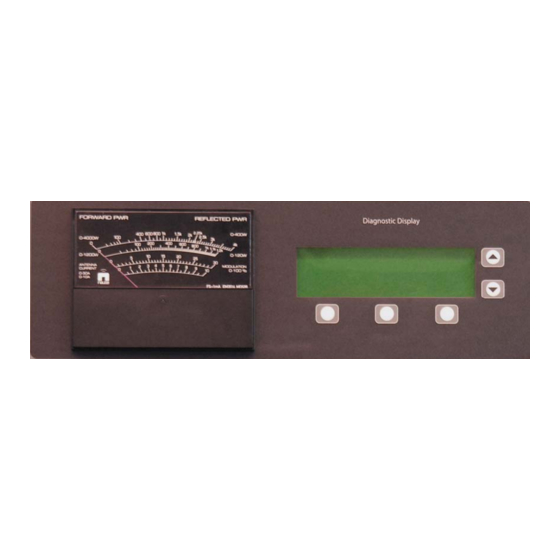
3.5.1 Front Panel Diagnostic Display – a menu-driven The front panel is the primary local user user interface screen - with five interface for the transmitter. Control and associated push-buttons - which allows indicators are grouped into four sections of control and monitoring of the transmitter’s the panel (see Figure 3-1) as follows: critical parameters and modes of... -
Page 46: Exciter Interface Pwb
3.5.2 Exciter Interface PWB 3.5.5 Miscellaneous Control and Controls and Indicators Exciter Controls and Indicators Figure 3-4 and Table 3-3 identify and Table 3-6 describes the miscellaneous describe the controls and indicators on the controls and indicators of the control/ exciter interface PWB (A2). - Page 47 Table 3-1: Front Panel - System Diagram Controls and Indicators PANEL MARKING DESCRIPTION Exciter When turned on (red), typically indicates a failure has occurred in the active exciter (side A or B). This alarm will initiate a changeover in dual transmitters; the side of the transmitter designated as standby will be operating as the active side.
-
Page 48: Vector-Lp Transmitter Front Panel - Control Section
Figure 3- - 3 Vector-LP Transmitter Front Panel – Control Section Page 3-6 Vector-LP Radio Beacon Transmitter Technical Instruction Manual Issue 1.1 Section 3 Operating Instructions... -
Page 49: Front Panel - Control Section Controls And Indicators
Table 3-2: Front Panel - Control Section Controls and Indicators PANEL DESCRIPTION MARKING Power Increase Pushbutton switch that increases the RF output power level of the transmitter. RF power is increased from minimum power to maximum power in approximately 200 steps. Each step will increase the output voltage of the switch mode power supplies to the RF power modules linearly –... -
Page 50: Part Of Napi76A/02 Exciter Interface Pwb A2
CR23 CR24 DGPS BEACON DGPS BEACON CR25 CR26 CR27 CR28 DGPS BEACON DGPS BEACON DGPS BEACON CR10 CR11 CR12 CR13 CR14 DGPS BEACON CR18 CR15 CR16 Figure 3- - 4 Part of NAPI76A/02 Exciter Interface PWB A2 Page 3-8 Vector-LP Radio Beacon Transmitter Technical Instruction Manual Issue 1.1 Section 3 Operating Instructions... -
Page 51: Exciter Interface Pwb Controls And Indicators
Table 3-3: Exciter Interface PWB Controls and Indicators PANEL REF DES DESCRIPTION MARKING E1, E2, Key CW Shorting jumpers that are installed in positions determined by E3, E8, Jumpers the type of transmitter. In NDB transmitters, the jumpers are factory installed in position 2. No user adjustment is required. E4, E5, DGPS/BEACON Bi-position selection jumpers that are installed in positions... -
Page 52: Part Of Napi78B/02 Remote Interface Pwb A3
R163 E13 - E15 E5 – E8 Figure 3- - 5 Part of NAPI78B/02 Remote Interface PWB A3 Page 3-10 Vector-LP Radio Beacon Transmitter Technical Instruction Manual Issue 1.1 Section 3 Operating Instructions... -
Page 53: Remote Interface Pwb Controls And Indicators
Table 3-4: Remote Interface PWB Controls and Indicators PANEL REF DES DESCRIPTION MARKING Press-To- Bi-position selection jumper that is installed based on the type Talk/Phantom of mode to enable voice operation. The jumper is factory Feed installed for ‘press-to-talk’ mode, position A (shorting pins 1 and 2). -
Page 54: Nape70C Rf Synthesizer Pwb A5 And A8
E1/E2 S1-S5 IPM BAL NAPE NAUTEL ASSY 10MHz 194-3060 SER. RF SYNTHESIZER INPUT 1 2 3 OPEN SYMMETRY ADJ EXT INT ENABLE DISABLE HIGH SOURCE EXT INT FREQUENCY (kHz) x1000 x100 x0.1 GRID1 A B C D E F M1940145 V1... -
Page 55: Rf Synthesizer Pwb Controls And Indicators
Table 3-5: RF Synthesizer PWB Controls and Indicators ITEM PANEL DESCRIPTION (Ref MARKING E1, E2 REF (10 MHz) Bi-position selection jumpers used to configure the RF synthesizer PWB to use either an internal or external 10 MHz reference generator. Jumpers are always set to INT (internal, shorting pins 2 and 3) for Vector-LP transmitters. - Page 56 Table 3-6: Miscellaneous Control and Exciter Controls and Indicators PANEL REF DES DESCRIPTION MARKING A1E1 No user adjustment should be required. Always installed in A1E2 position B. A1E3 No user adjustment required. A link is soldered between pins 1 and 3 for Vector-LP transmitters. A1LS1 SPEAKER Provides an audible signal for local monitoring of the...
-
Page 57: Miscellaneous Rf Power Stage Controls And Indicators
Table 3-7: Miscellaneous RF Power Stage Controls and Indicators PANEL REF DES DESCRIPTION MARKING A12A1DS1 MODULE When turned on (amber), indicates that RF power module A INSTALLED or B is installed in the transmitter. A13A1DS1 A12A1DS2 MODULE ON When turned on (green), indicates that RF power module A or B is on and is contributing to the transmitter’s RF output. -
Page 58: Naps35 Battery Boost Pwb A16A1 (Optional)
E7, E9, E10 250W 125W 250W 125W CHARGER 250W 125W SMPS, 24/48V BATTERY BOOST NAPS35 SER. +24V +48V OUT + M2050021 V1 Figure 3- - 7 NAPS35 Battery Boost PWB A16A1 (Optional) Page 3-16 Vector-LP Radio Beacon Transmitter Technical Instruction Manual Issue 1.1 Section 3 Operating Instructions... -
Page 59: Battery Boost Pwb Controls And Indicators
Table 3-8: Battery Boost PWB Controls and Indicators PANEL REF DES DESCRIPTION MARKING A16A1DS1 +15V When turned on (green), indicates the +15 V power supply voltage is being applied to the battery boost PWB and its switch mode PWM IC U4. A16A1E5 +24V/+48V Bi-position selection jumper that is installed in the position... - Page 60 Events Log Events Log Jul 27 2007 Jul 27 2007 SELECTIONS Settings Settings 13:52:45 13:52:45 Peripherals Peripherals Nautel Nautel RCMS Settings RCMS Settings Select Select Meters Meters Figure 3-9 Diagnostic Display – Main Menu 3.6 DIAGNOSTIC DISPLAY 3.6.2 Main Screens...
-
Page 61: Flow Diagram - Diagnostic Display Functions
Diagnostic Display (GUI) Functions Reference (organized by menu hierarchy) Paragraph MAIN MENU Meters Status 3.6.3 Power 3.6.15 Changeover Control 3.6.4 Events Log 3.6.5 Settings Set Real Time Clock 3.6.6 Monitor Settings 3.6.7 Monitor Timeout 3.6.7 (b) Power Thresholds 3.6.7 (d) Automatic Reset 3.6.7 (f) Mod % Thresholds... -
Page 62: Viewing Faults
Status Status Power Power Jul 27 2007 Jul 27 2007 Settings Settings 13:52:45 13:52:45 Peripherals Peripherals Nautel Nautel RCMS Settings RCMS Settings Select Select Meters Meters 12:43:16 Power: 12:43:16 Power: 12:43:16 Power: 0W Side A Bypass 0W Side A Bypass... -
Page 63: Setting Real Time Clock
Jul 27 2007 Jul 27 2007 mode, a list of events is displayed, sorted Settings Settings 13:52:45 13:52:45 Peripherals Peripherals chronologically, with a root-cause Nautel Nautel RCMS Settings RCMS Settings description of the event. Select Select Meters Meters NOTE Refer to Table 3-9 for a list of non-alarm... -
Page 64: Setting Rf Monitor Limits
Events Log Thresholds and press Select. The Jul 27 2007 Jul 27 2007 Settings Settings 13:52:45 13:52:45 following message is displayed. Press Peripherals Peripherals Nautel Nautel RCMS Settings RCMS Settings Continue to proceed. Select Select Meters Meters 12:43:16 Power: 12:43:16 Power:... - Page 65 (e) Use f and g to highlight the desired Waits the Fault 1 delay period (40 min) monitor timeout field and press Modify: Attempts to reset transmitter. If The low limit is factory set for 3.00 dB. successful, Automatic Reset schedule Adjust using f and g.
-
Page 66: Meter Settings
Events Log 1200 1200 Jul 27 2007 Jul 27 2007 Settings Settings Reflec. Power: 0.0W Reflec. Power: 0.0W 13:52:45 13:52:45 Peripherals Peripherals Nautel Nautel RCMS Settings RCMS Settings VSWR: 1.00 VSWR: 1.00 Select Select Meters Meters Save Backup Save Backup Modify... -
Page 67: Selecting Analog Meter
DC Curr B: 0.00A ( ) DC Curr B: 0.00A ( ) 13:52:45 13:52:45 Peripherals Peripherals DC Curr B: 0.00A ( ) DC Curr B: 0.00A ( ) Nautel Nautel RCMS Settings RCMS Settings Choose Scale Choose Scale Select Select... -
Page 68: Configuring The Sonalert
Events Log Jul 27 2007 Jul 27 2007 Settings Settings follows: 13:52:45 13:52:45 Peripherals Peripherals Nautel Nautel RCMS Settings RCMS Settings 12:43:16 Power: 12:43:16 Power: 12:43:16 Power: 0W Side A Bypass 0W Side A Bypass 0W Side A Bypass Main Menu... -
Page 69: Changing Factory Calibrated Settings
Stopped 00:05:00 15:17:38 15:17:38 Peripherals Peripherals Main Menu Main Menu Toggle Toggle Back Back Nautel Nautel RCMS Settings RCMS Settings Select Select Meters Meters (b) Use f and g to highlight Timed Shutdown, Interval or Auto Assert, noting: 12:43:16 Power:... -
Page 70: Calibrating Diagnostic Display Meters
Calibrate Meters Calibrate Meters CAUTION PDM B: 0.00 PDM B: 0.00 Protection threshold levels are factory set and do not normally require adjustment. Contact Nautel prior to attempting to alter Main Menu Main Menu Modify Modify Back Back these settings. Failure to comply could result in equipment damage. -
Page 71: Setting Maximum Output Limitations
3.6.12.3 SETTING MAXIMUM OUTPUT (b) To edit a parameter, press Modify and then f or g to adjust the value. If the LIMITATIONS The maximum allowable output gain can be Set Duty Cycle and Set Forward Power adjusted in terms of carrier reference. group is selected to Modify, use the Next button to toggle between the two items. -
Page 72: Viewing And Setting Peripherals
Jul 27 2007 Settings Settings (a) Audio Levels: Select the desired 13:52:45 13:52:45 Peripherals Peripherals Nautel Nautel parameter, using f or g. To edit, press RCMS Settings RCMS Settings Modify and then use f or g to adjust Select Select... -
Page 73: Viewing Power Module Status
Frame Format 12:43:16 Power: 12:43:16 Power: 12:43:16 Power: 0W Side A Bypass 0W Side A Bypass 0W Side A Bypass Keyer Modulation Keyer Modulation 12:43:16 Power: 12:43:16 Power: 0W Side A Bypass 0W Side A Bypass Modulation Modulation Frame Sequence Frame Sequence Press up/down Press up/down... -
Page 74: Atu Controls
Back Back 3.6.13.3 ATU CONTROLS If a Nautel antenna tuning unit (ATU) is being (c) In the coil control screen shown below, used, view and edit its control parameters as use f and g to select the desired coil to... -
Page 75: Testing The Standby Side
Site Control Board. selected coil to be manually tuned. Use f and g to slew the coil high or low. If a Nautel ATU is used and a serial Press Done when complete. interface is connected to the... -
Page 76: Checking Modules
Settings through 16 on TB3 of the remote control/ 15:17:38 15:17:38 Peripherals Peripherals monitor interface PWB. RCMS Settings RCMS Settings Nautel Nautel Select Select Meters Meters (b) Return to previous menu by pressing Back. Page 3-34 Vector-LP Radio Beacon Transmitter Technical Instruction Manual Issue 1.1... -
Page 77: Setting Monitor Points
To modify Tx Address, use f and g. 3.6.14.2 SETTING MONITOR POINTS Set the site interface PWB’s monitor points as follows: Press Toggle to set Connection Mode to DIRECT or MODEM. When MODEM is selected, the following 12:43:16 Power: 12:43:16 Power: 12:43:16 Power: 0W Side A Bypass 0W Side A Bypass... - Page 78 3.6.15 Viewing Power Related (a) From the meter screen, press Power. Parameters and Setting ATU The current forward power, reflected Current Feedback power, carrier reference, VSWR, View the transmitter’s power menu and, if antenna current, B+ voltage (for the necessary, set the status of the ATU active side’s power supply) and dc current feedback circuit as follows: current (for the active side’s power...
-
Page 79: Introduction
NOTE NOTE If an in-tolerance condition cannot be Nautel recommends all instructions be attained with the specified routine followed in the order presented, particularly adjustment, discontinue testing until the by personnel who are not familiar with... -
Page 80: Exciter Panel And Rear View
Figure 4-1 Exciter Panel and Rear View Page 4-2 Vector-LP Radio Beacon Transmitter Technical Instruction Manual Issue 1.1 Section 4 Testing and Adjustment... -
Page 81: Test Equipment Required
4.3.1.3 Some of the transmitter’s PWBs WARNING may be duplicated and connected as active If there is a jumper between TB1-19 and (main) and reserve (standby). The front TB1-20 on the remote interface PWB, panel diagnostic display provides selection safety features provided by the external of the active side (A or B). -
Page 82: Standard Adjustments
NOTE 4.3.5.3 SETTING DEFAULT MONITOR During initial turn-on and adjustment of STATES transmitter power, the diagnostic display’s If the optional NDB site interface PWB (A4) meters screen should be monitored. is installed, see 3.6.14.1 and 3.6.14.2 to set default monitor states. Various input parameters, such as Forward Power, Average B+ Voltage, 4.3.5.4 ADJUSTING AUDIO LIMITER... - Page 83 4.3.5.5 SETTING CHANGEOVER MODE modes (see 3.6.7). The thresholds AND RF MONITOR THRESHOLDS should be updated with the desired If a standby side is being used, adjust the values. transmitter’s high and low RF power limits, low modulation and tone levels, and the NOTE monitor delay period, as follows: At this point the system has automatically...
- Page 84 Ensure that antenna current feedback (g) Select Main Menu/Peripherals/Keyer is OFF (disabled, see 3.6.15) before Settings/Audio Levels. proceeding. (h) Note the modulation level. Decrease (b) Select the exciter (A or B) that will be the Keying Pot level (see 3.6.13.1). Power should be inhibited when 60 r operational for the next year as the Main Side (see 3.6.4) and note the...
- Page 85 (j) If the requirements of step (i) are not (e) In the Audio Levels menu, while met, set the transmitter to operate in monitoring the Mod %, increase the BYPASS mode. Press Reset in the Keying Pot value until the Mod % is as Status menu.
-
Page 86: Non-Standard Adjustments
(h) In the Keyer Modulation menu, set NOTE Modulation and Tone Generator to ON. When antenna current feedback is Set the Tone Frequency to 400 Hz or enabled, the transmitter will adjust the 1020 Hz. output power to ensure that antenna current remains constant. - Page 87 65 V. Stop increasing power if at any 1800 kHz), you will need to change the RF time: filter PWB (A14). Contact Nautel. the PA voltage between RF power (a) Turn off the RF power and the ac and modules varies by more than 5%, or dc circuit breakers.
- Page 88 (i) In the Maximum Output Gain menu Adjust the reading to the same value (see 3.6.12.3), calibrate the duty cycle calculated in step (h). Record this and forward power as follows: level. Press Done. Highlight the value for Set Duty Cycle. (n) Increase the power until maximum Press Modify.
- Page 89 NOTE (c) Set RF output power to 0 W. Press RF When you exit the Calibrate Meters menu a On. Monitor the external current while message is displayed indicating that you slowly increasing the power to half of have made changes. You will be prompted the reflected power limit.
- Page 90 (k) Verify the reflected power cutback is (e) Adjust the Low AC Voltage value until below 30 W (for VR250) or 15 W (for the voltage at TP19 matches the low VR125). Press RF Off. ac voltage reference calculated in step (b).
- Page 91 NOTE Change the value for Set Forward If an external RF generator is producing Power to match the power calculated the RF drive, verify its output waveform is in step (e). Press Done. symmetrical. (g) If the transmitter is operating at full 4.3.6.10 EQUALIZING EXCITER GAIN power, go to step (o).
-
Page 92: Battery Boost Pwb
4.3.6.11 CALIBRATING BATTERY (h) Press RF On and increase the RF VOLTAGE, BATTERY CURRENT AND output to rated power. CHARGER CURRENT (Optional) (i) Use a clip-on dc current meter to NOTE measure the current between the This procedure applies to transmitters that battery and TB1-3 of the battery boost use a dc power source and the battery PWB. -
Page 93: Cw Signal Set To Fill Display
4.3.6.13 ADJUSTING SPEAKER VOLUME See Setting Protection Thresholds (3.6.12.2). Adjust the Audio parameter as desired. 4.3.6.14 READING MODULATION LEVEL Read the modulation level as follows: (a) Connect an oscilloscope to the RF MONITOR connector (J8) on the remote interface PWB (A3). Figure 4-3: CW signal with position (b) Set the exciter in CW mode: use adjusted to mid-point of display... - Page 94 (g) If the modulation level requires adjustment select Main Menu/ Peripherals/Keyer Settings/Audio Levels. (h) Adjust the Keying Pot (in Press-to-talk mode adjust the PTT Keying Pot) to get the desired level of modulation. This adjustment will affect both exciters. (i) Check if the reading on the diagnostic display agrees with the oscilloscope measurement.
-
Page 95: General
Vector-LP Radio Beacon Transmitter TECHNICAL INSTRUCTION MANUAL Section 5 MAINTENANCE AND TROUBLESHOOTING x Once a year, clean the transmitter 5.1 GENERAL This section contains scheduled and using a vacuum cleaner and a soft- corrective maintenance information for the bristle brush to remove loose dirt. Use Vector-LP transmitter. -
Page 96: Corrective Maintenance
(paragraph 3.6.13.4). transmitter site. For off-air troubleshooting procedures, 5.3.1.1 Remote Troubleshooting Nautel recommends you connect the output to a precision 50 : , resistive Remote on-air troubleshooting consists of monitoring the transmitter's RF output dummy load (rated for twice the using an on-air monitor and polling the transmitter’s maximum carrier power). -
Page 97: Troubleshooting Front Panel Alarms
5.4.1 Discharging of Personnel The diagnostic display’s meter screen Maintainers should be electrically has real-time meter indications (e.g., discharged by a suitable grounding forward power) to assist in fault system (anti-static mats, grounding analysis. straps) during removal of an assembly from the exciter and while handling the The diagnostic display’s main screen assembly for maintenance procedures. - Page 98 (g) If replacement of a suspect PWB or interphase PDM driver PWB. The assembly does not remove the fault suspect PWB should be replaced as condition, contact Nautel. detailed in paragraph 5.8.1.2. NOTE For dual side transmitters, a changeover to the standby side should also occur.
-
Page 103: Replacing An Rf Power Module
5.6 REPLACING AN RF POWER (d) Grip the flanged edge at the top of the MODULE RF power module and carefully lift the The diagnostic display status messages module out of the transmitter cabinet. indicate which RF power module caused an alarm. -
Page 104: Rf Power Module Securing Hardware
Battery Boost Assembly A16 Replacement: Remove SHIPPING SCREWS: Remove TOP COVERS: Remove five screws from bottom for each RF power screws from top cover for each RF module. NOTE: Shipping screws may have power module. Reinstall this been removed during installation. They are hardware after module replacement not required after module replacement. -
Page 105: Fet Checking/Replacement
Nautel parts referenced below. (e) If the requirements of steps (c) and (d) x FETs Q1 and Q2 (Nautel Part # QR54) are not met, replace the device as of switch mode power supply PWB A2 detailed in steps (i) through (m). -
Page 106: Exciter Panel Pwb Replacement
See 5.8 first. The exciter interface PWB (cupped) washer with a new washer (A2) physically interconnects with the RF (Nautel Part # HZ48, located in synthesizer PWBs (A5 and A8) and the ancillary kit). Apply a thin, even coat interphase PDM driver PWBs (A6 and A9). -
Page 107: Exciter Monitor/Generator Pwb Replacement
NOTE 5.8.1.3 EXCITER INTERFACE PWB When an RF synthesizer PWB configured REMOVAL/REPLACEMENT to operate from an external RF drive (See 5.8 and 5.8.1 first) source is installed in a transmitter, its (a) Remove all connections to the top and frequency synthesizer must be operational bottom of the exciter interface PWB. -
Page 108: Interface Pwb Replacement
5.8.3 Interface PWB Replacement (a) Press the Control - RF OFF switch. See 5.8 first. Remove the interface PWB Switch off the ac power and disconnect (A11) as follows. the dc supply, if applicable. NOTE (b) Disconnect the dc input wiring from in The interface PWB is located on the back of terminal block A16TB1 the exciter panel (see Figure 4-1). -
Page 109: Introduction
NDB provided over several optional interfaces. applications. The transmitter also has provision to interface with a Nautel antenna tuning unit 6.2 TRANSMITTER OVERVIEW (ATU), using an isolated RS485 serial link. The transmitter operates at one fixed... -
Page 113: Interface Pwb
The ac input is applied through 10 A circuit 6.3.3 Battery Boost PWB (optional) breaker U5 and line filter U6. The ac voltage See Figures SD-1 and SD-25. The battery for the RF power stage (RF power modules boost PWB is a boost type switching power A12 and A13) passes through thermistor RT1 supplies that provide a regulated B+ supply and choke L1. -
Page 114: Exciter Stage
6.4 EXCITER STAGE position for RF relay K1. If a changeover is See Figures 6-2 and SD-2. In dual indicated by a low on either U4:3 or U4:4, the configuration the exciter stage contains two relay for the main side will open and the relay independent exciter sections (A and B) which for the standby side will close. - Page 115 6.4.2.1.1 DDS Control Information DesiredOut putFrequen The RF carrier frequency is set using five SYSCLK binary coded decimal (BCD) switches (S1 through S5). When a current-sink-to-ground The 10 MHz clock input is coupled with U5's is applied at the Reset DDS input, or during internal programmable reference clock turn on, the microprocessor monitors these multiplier.
-
Page 116: Interphase Pdm Driver Pwbs
6.4.2.9.1 Internal gc Source 6.4.2.7 BALANCED DRIVE The balanced drive buffer is a switching To use the integral numerically controlled circuit that ensures the rise and fall times of oscillator’s output as the RF drive source, its output square wave are minimal. The g set the shorting shunt posts as follows: signal is a 15 V peak-to-peak square wave x E1 in INT position (pins 2 and 3 shorted) - Page 117 The B+ Sample input at P1-3 is a dc voltage GAIN TRIM potentiometer R31 provides a directly proportional to the B+ voltage being nominal 10% adjustment in the carrier level applied to the transmitter's RF power stage. ref output of U3B. In dual exciter applications, When the B+ voltage is 236 V (for VR250) or it is adjusted to compensate for tolerance 167 V (for VR125), the B+ Sample input and,...
-
Page 121: Timing Diagram For Pdm Differential Amplifier
Carrier Reference Level Ramp PDM 1 Figure 6-3 Timing Diagram for PDM Differential Amplifier 6.4.3.5 INTERPHASE PDM 6.4.3.5.1 PDM1 Generator GENERATOR The PDM1 generator consists of U10B, The interphase PDM generator consists of transistors Q4, Q5, and associated two identical variable pulse duration components. - Page 122 6.4.3.6 PDM FAULT DETECTOR disconnect the PDM 1 output from the The PDM fault detector circuit contains a transmitter circuits when the PDM fault voltage controlled switch that controls the detector output is a current-sink-to-ground 'set/'reset' status of the shutback latch (logic low).
-
Page 123: Exciter Monitor/Generator Pwbs
6.4.4 Exciter Monitor/Generator 6.4.4.2 PRESS-TO-TALK PWBs The input to U11:11 indicates to the exciter See Figures SD-19 and SD-20. The exciter/ monitor/generator PWB which mode of monitor/generator PWBs [A7 (exciter A) and operation it should be operating in. It will A10 (exciter B, if used)] perform the react by adjusting the U16:1 that controls the following functions:... -
Page 124: Control/Monitor Stage
6.4.4.5 FORWARD POWER MONITOR Monitors critical parameters and turns off A dc voltage, proportional to the transmitter’s (shuts back) or reduces (cuts back) the forward power, is applied to the Forward Carrier Ref voltage when defined fault Power Sample input (P1-1). This voltage is threshold limits are exceeded. - Page 125 6.5.1.2.1 Ac Supply Voltage Turning off the RF output reduces the refld The Ac Power input (J4-21) is an pwr sample input to 0 V. The Carrier Ref (A) unregulated dc voltage that is proportional to and (B) outputs are restored to their the ac source.
- Page 126 6.5.1.3.2 Forward Power 6.5.1.3.5 Low Voltage Power Supplies The Fwd Pwr Sample input (J1-3) is a dc Attenuated, buffered samples of all low voltage dc power supplies (+24 V, r 15 V and voltage which represents the forward power at the transmitter’s RF output.
- Page 127 6.5.2 Remote Interface PWB 6.5.2.3 RS232 and RS422 Interface See Figures SD-11 through SD-13. The U19, U18, U12, convert the TTL levels remote interface PWB (A2A2) performs the produced by the control/display PWB to following functions: RS232 and RS422 levels for external control/monitoring of the transmitter.
-
Page 128: Diagnostic Display
6.5.2.6.3 Audio Limiting 6.5.3.3 CONTROL SWITCHES U10:B, U10:C, U10:D, Q7, and their The control switches determine the associated components form the audio transmitter’s control location (local or remote) limiter. The limiter will raise an alarm at and its RF status (on or off). U10:13 when the audio signal goes above a pre-defined threshold. -
Page 129: Ndb Site Interface Pwb (Optional)
6.5.4 NDB Site Interface PWB 6.5.4.2 Site Control Points (Optional) Shift registers U17 and U19, controlled by See Figures SD-14 and 15. The NDB site microcontroller U13 over the SPI bus will interface PWB (A4), if purchased, provides: control relays K1 to K16. Control point logic levels are determined by the control/display 16 optically isolated monitor inputs. -
Page 130: Rf Power Stage
6.6 RF POWER STAGE 6.6.1.1.2 Switching Signal See Figures 6-5 and SD-4. The RF power IC U3 is a high current FET driver that stage produces the transmitter’s final RF provides a switching PWM signal (0-18 V) to output. It contains the RF power modules the primary of transformer T2. -
Page 131: Rf Filter Pwb
6.6.1.2.2 Gate Bias Drive Signal 6.6.1.3.3 B+ Switching MOSFET U7, Q2 and associated components Power MOSFET Q1 is connected to switch generate a 15 V square wave at 263 kHz to the B+ voltage at the on/off ratio of the PDM drive the gate bias drive in the modulator. -
Page 135: Rf Power Probe Pwb
6.6.2 RF Filter PWB The in-phase voltages are summed, rectified See Figure SD-4. The RF filter PWB (A14) is by CR35, low-pass filtered by L9/C53/L11, a band pass filter that attenuates the resulting in a dc voltage being applied to the harmonics of the square wave output applied Fwd Pwr Sample output (J1-1). - Page 136 6.7 MODULATION DEPTH WHEN A typical radiobeacon antenna is relatively USING A HIGH ‘Q’ ANTENNA inefficient, since it is very short when When the transmitter's output is connected to compared with the wavelength of the carrier a high 'Q' antenna system, the modulation frequency.
-
Page 137: Simplified Principles Of Class 'D' Operation
SIMPLE CLASS 'D' OPERATION If the switch is opened and closed with a 50% duty cycle, a square wave at the switching frequency will result at the filter input. If the filter is designed to pass the switching frequency, but attenuate its harmonics, a sine wave is applied to the load. -
Page 139: Introduction
To locate the information for a specific part, the assigned reference designation for the Cable harnesses that are assigned a part must be known. In addition, the Nautel numbered Nautel part (e.g., 205-8001) configuration control number (e.g., NAPC147B) assigned to the assembly... -
Page 140: Oem Code To Manufacturer Cross-Reference
(address, telephone number, fax number, etc.) shall be displayed. Please contact 7.5.4 Vendor # Column: Nautel if a part cannot be obtained (see also This column contains an original equipment ON-LINE PART QUOTES in this manual’s manufacturer's part number for a part. A Warranty section). -
Page 141: Common Abbreviations/Acronyms
7.7 COMMON ABBREVIATIONS/ MTA - Denotes item is a Mass Termination ACRONYMS Assembly connector. The following abbreviations/acronyms may appear in Description column: SIP - Single In-line Package DIP - Dual In-line Package SMT - Denotes item is designed to be installed using Surface Mount IDC - Denotes item is an Insulation Technology. -
Page 142: Manufacturer's Index
Edac Incorporated IXYS See 0A5K5 33062 Ferronics Incorporated LITEON Liteon Inc. 35005 Dale Electronics Limited MAGNE MagneTek Triad 37338 Nautel Limited MICREL Micrel Incorporated 36AB3 Pacific Display Devices MURATA Murata 3DX59 Citizen America Corporation ONSEMI ON Semiconductors 3N087 Mill-Max Manufacturing Corporation... -
Page 143: Family Tree - Vector-Lp Radio Beacon Transmitter
VECTOR - LP NARB18 CONTROL/DISPLAY PWB EXCITER INTERFACE REMOTE INTERFACE SITE INTERFACE NAPC147B NAPI76A/02 NAPI78B/02 NAPI79 OR NAPI80 (OPTIONAL) RF SYNTHESIZER PWB INTERPHASE PDM DRIVER EXTERNAL MONITOR/GENERATOR PWB RF SYNTHESIZER PWB NAPE70C NAPM11 NAPE76A/03 NAPE70C (NDB) (DUAL NDB) INTERPHASE PDM DRIVER EXTERNAL MONITOR/GENERATOR PWB INTERFACE PWB NAPM11... - Page 145 Display Mod 195-3019 REFDES DESCRIPTION NAUTEL # VENDOR # OEM CODE Conn, Header, Ribbon Cbl, 20Pin JQ55 103308-5 00779 Display,LCD,240x60 Graphic,Ext Temp UT81 C10815(STATIC) 36AB3 PACIFIC DISPLAY DEVICES Ribbon Cable Assy 195-3023 REFDES DESCRIPTION NAUTEL # VENDOR # OEM CODE...
- Page 146 RF Transformer Assy 205-5050 REFDES DESCRIPTION NAUTEL # VENDOR # OEM CODE Connector, Quick-Dis, M,1/4 Tab, PWB HR26 1287 91833 Connector, Quick-Dis, M,1/4 Tab, PWB HR26 1287 91833 Connector, Quick-Dis, M,1/4 Tab, PWB HR26 1287 91833 Connector, Quick-Dis, M,1/4 Tab, PWB...
- Page 147 Cableform, Vector-LP 205-8001 REFDES DESCRIPTION NAUTEL # VENDOR # OEM CODE MTA, Standard Dust Cover, 8 pin JU07 640551-8 09482 MTA, Keyed Closed End Housing,8 pin,22AWG JU28 644463-8 00779 MTA, Standard Dust Cover, 8 pin JU07 640551-8 09482 MTA, Keyed Closed End Housing,8 pin,22AWG...
- Page 148 Continued from previous page Cableform, Vector-LP 205-8001 REFDES DESCRIPTION NAUTEL # VENDOR # OEM CODE MTA, Keyed Closed End Housing,4 pin,22AWG JU27 3-644463-4(ROHS) 00779 Conn, Socket, D-Sub, HDP-20, 25 pin JR38 205207-1 09482 Conn, Plug, D-Sub, 25 pin, HDP-20 JR39...
- Page 149 Ribbon Cable Assy 205-8019 REFDES DESCRIPTION NAUTEL # VENDOR # OEM CODE W01P1 Conn, Recept, Ribbon Cable, 40 pin JP51 746288-9 00779 W01P2 Conn, Recept, Ribbon Cable, 40 pin JP51 746288-9 00779 W02P1 Conn, Recept, Ribbon Cable, 40 pin JP51...
- Page 150 Cabinet-Vector-LP 205-8075 REFDES DESCRIPTION NAUTEL # VENDOR # OEM CODE Cord, Line Assy, SJT, 250V,10A JN50 17569 VOLEX TB01 Terminal Block, 4-Pos, Double, 61A JF27 G10/4 5Y407 Wire Assy Cabinet Vector-LP 205-8073 205-8073 37338 IP66 Cabinet w/Vector-LP Assy 205-8080 REFDES...
Need help?
Do you have a question about the Vector-LP VR125 and is the answer not in the manual?
Questions and answers