Sign In
Upload
Manuals
Brands
Nautel Manuals
Transmitter
Vector-LP VR125
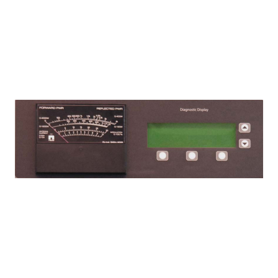
Nautel Vector-LP VR125 Beacon Transmitter Manuals
Manuals and User Guides for Nautel Vector-LP VR125 Beacon Transmitter. We have
1
Nautel Vector-LP VR125 Beacon Transmitter manual available for free PDF download: Technical Instruction Manual
Nautel Vector-LP VR125 Technical Instruction Manual (150 pages)
Radio Beacon Transmitter
Brand:
Nautel
| Category:
Transmitter
| Size: 1.56 MB
Table of Contents
Reference Designations
4
Electrical Schematics
5
Declaration of Conformity
7
Table of Contents
9
Introduction
10
Factory Support
19
Purpose and Scope of Manual
19
Purpose of Equipment
19
Remote Interface
20
Mechanical Description
20
Glossary of Terms
20
Recommended Site Test Equipment
21
Glossary of Terms
22
Transmitter Dimensions
23
Transmitter Weights
23
Transmitter Clearances
23
Air Flushing
23
Cooling and Heating
23
Work Area
23
Preparation for Use and Installation
23
Introduction
23
Preparation for Use
23
Transmitter Room Requirements
23
Lightning Protection
24
Station Reference Ground
24
Ac Power Source
24
Ac Wiring
24
Vector-LP Transmitter Environment Considerations
25
Antenna Feed Cable
29
Antenna Tower
29
External Control/Monitor Wiring
29
Electrical Power
29
Ac Voltage Source
29
External Ac Switching
29
DC Voltage Source
29
Antenna System
30
RF Feed Cable
30
Internal DDS Source
30
External Interlocks
31
Remote Control Circuits
31
On/Off Control
32
Charger Alarm
32
Standby Code
32
Press-To-Talk Input
32
User Assigned Information
32
Carrier Frequency
32
Keyed Tone Frequency
32
Vector-LP Radio Beacon Transmitter Technical Instruction Manual Feb.24.09
32
Identification Code
32
Standby Codes
32
Serial Port Features
33
Remote Control and Monitoring Interface
33
ATU Interface
33
RF Monitoring Sample
33
Parts Supplied by Nautel
33
Parts Not Supplied by Nautel
33
Test Equipment and Special Tools
33
Available Options
33
Installation
35
Acceptance of Shipment
35
Unpacking Instructions
35
Visual Inspection
35
Cabinet Mounting
36
Installing External Control/Monitor Wiring
36
Installing DC Power Source Wiring (Optional)
37
RF Filter PWB Tap Settings Vs Frequency (Standard Frequency Band)
38
Commissioning
39
Precautions
39
Turn-On Prerequisites
39
Initial Turn-On
39
Operating Instructions
43
Introduction
43
Precautions
43
Emergency Shutdown
43
Turn off RF Output
43
Complete Shutdown
43
External Safety Interlock
43
Electrostatic Discharge Protection
44
Controls and Indicators
44
Mechanical Drawings
44
Front Panel
45
Exciter Interface PWB
46
Remote Interface PWB
46
Vector-LP Transmitter Front Panel - Control Section
48
Front Panel - Control Section Controls and Indicators
49
Part of NAPI76A/02 Exciter Interface PWB A2
50
Exciter Interface PWB Controls and Indicators
51
Part of NAPI78B/02 Remote Interface PWB A3
52
Remote Interface PWB Controls and Indicators
53
NAPE70C RF Synthesizer PWB A5 and A8
54
RF Synthesizer PWB Controls and Indicators
55
Miscellaneous RF Power Stage Controls and Indicators
57
NAPS35 Battery Boost PWB A16A1 (Optional)
58
Battery Boost PWB Controls and Indicators
59
Flow Diagram - Diagnostic Display Functions
61
Viewing Faults
62
Setting Real Time Clock
63
Setting RF Monitor Limits
64
Meter Settings
66
Selecting Analog Meter
67
Configuring the Sonalert
68
Changing Factory Calibrated Settings
69
Calibrating Diagnostic Display Meters
70
Setting Maximum Output Limitations
71
Viewing and Setting Peripherals
72
Viewing Power Module Status
73
ATU Controls
74
Testing the Standby Side
75
Checking Modules
76
Setting Monitor Points
77
Introduction
79
Exciter Panel and Rear View
80
Test Equipment Required
81
Standard Adjustments
82
Non-Standard Adjustments
86
Battery Boost PWB
92
CW Signal Set to Fill Display
93
General
95
Corrective Maintenance
96
Troubleshooting Front Panel Alarms
97
Replacing an Rf Power Module
103
RF Power Module Securing Hardware
104
Fet Checking/Replacement
105
Exciter Panel Pwb Replacement
106
Exciter Monitor/Generator PWB Replacement
107
Interface PWB Replacement
108
Introduction
109
Interface PWB
113
Exciter Stage
114
Interphase PDM Driver Pwbs
116
Timing Diagram for PDM Differential Amplifier
121
Exciter Monitor/Generator Pwbs
123
Control/Monitor Stage
124
Diagnostic Display
128
Front Panel Metering
128
NDB Site Interface PWB (Optional)
129
Rf Power Stage
130
RF Filter PWB
131
RF Power Probe PWB
135
Simplified Principles of Class 'D' Operation
137
Introduction
139
Oem Code to Manufacturer Cross-Reference
140
Common Abbreviations/Acronyms
141
Manufacturer's Index
142
Family Tree - Vector-LP Radio Beacon Transmitter
143
Advertisement
Advertisement
Related Products
Nautel Vector-LP VR250
Nautel VS300
Nautel V10
Nautel VX300
Nautel VX600
Nautel VX1.5
Nautel VX5
Nautel VX6
Nautel VX4
Nautel V3.5
Nautel Categories
Transmitter
Antenna
Recording Equipment
Industrial Equipment
Receiver
More Nautel Manuals
Login
Sign In
OR
Sign in with Facebook
Sign in with Google
Upload manual
Upload from disk
Upload from URL