Table of Contents
Advertisement
V10/V7.5/V5/V3.5
FM Broadcast
Transmitter
Installation and Operation Manual
Original Issue 3.5 ....................... 05 July 2007
Nautel Limited
10089 Peggy's Cove Road,
Hackett's Cove, NS, Canada B3Z 3J4
T. 877 6 nautel (628835) or +1.902.823.2233
F.+1.902.823.3183
info@nautel.com
U.S. customers please contact:
Nautel Inc.
201 Target Industrial Circle, Bangor ME 04401
T. 877 6 nautel (628835) or +1.207.947.8200
F.+1.207.947.3693
info@nautel.com
e-mail: support@nautel.com
www.nautel.com
© Copyright 2007 NAUTEL. All rights reserved.
Advertisement
Table of Contents
Troubleshooting

Subscribe to Our Youtube Channel
Related Manuals for Nautel V10


Summary of Contents for Nautel V10
- Page 1 Installation and Operation Manual Original Issue 3.5 ....... 05 July 2007 Nautel Limited 10089 Peggy's Cove Road, Hackett's Cove, NS, Canada B3Z 3J4 T. 877 6 nautel (628835) or +1.902.823.2233 F.+1.902.823.3183 info@nautel.com U.S. customers please contact: Nautel Inc. 201 Target Industrial Circle, Bangor ME 04401 T.
-
Page 3: V10/V7.5/V5/V3.5 Installation And Operation Manual Jul
Nautel for repair. The repairs will be made without charge to the Customer. Where warranty replacements or repair are provided under items 2 or 3, Nautel will pay that part of the shipping costs incurred in returning the part/assembly to the Customer. - Page 4 Nautel's field service department provides telephone technical assistance on a 24 hour, seven days a week basis. Requests by other media (facsimile or e-mail) will be responded to the next working day if received after Nautel's normal working hours. Contact the appropriate field service centre from the following: U.S.A.
- Page 5 CAUTION shall immediately precede the text to which it applies. NOTE A NOTE denotes important information pertaining to an operating procedure, condition, statement, etc., which is essential to highlight. A NOTE may precede or follow the text to which it applies. V10/V7.5/V5/V3.5 Installation and Operation Manual Jul.05.07...
- Page 6 (l) DON’T GIVE UP. Continue without interruption until the casualty is revived, or until a doctor pronounces the casualty dead. Four hours or more may be required. (m) DO NOT PROVIDE ANYTHING ORALLY while victim is unconscious. V10/V7.5/V5/V3.5 Installation and Operation Manual Jul.05.07...
- Page 7 14. For burns and bleeding, immobilize injured part using splints, if necessary, and keep patient in restful position during removal to hospital or expert medical attention. 15. In all cases, send for medical aid immediately. V10/V7.5/V5/V3.5 Installation and Operation Manual Jul.05.07...
- Page 8 Use a dry, unpainted pole, clean dry rope, dry rubber, or plastic water hose to separate the casualty from the contact. Keep as far away as possible. Do not touch the casualty until the casualty is free. V10/V7.5/V5/V3.5 Installation and Operation Manual Jul.05.07...
- Page 9 DO NOT cut, crush or grind devices because the resulting dust may be HAZARDOUS IF INHALED. Unserviceable devices should be disposed of as harmful waste. V10/V7.5/V5/V3.5 Installation and Operation Manual Jul.05.07...
-
Page 11: Table Of Contents
2.2.13 Remote Control Circuits 2.2.13.1 On/Off Control 2-10 2.2.13.2 Main Exciter Selection 2-10 2.2.13.3 Main IPA Selection 2-10 2.2.13.4 Main IPA Power Supply Selection 2-11 2.2.13.5 Main Fan Supply Selection 2-11 2.2.13.6 Preset Power Level Selection 2-11 V10/V7.5/V5/V3.5 Installation and Operation Manual Jul.05.07... - Page 12 2.2.21.5 Output Connector Option 2-16 2.2.21.6 Station Spares Kit Option 2-16 2.2.21.7 Site Spares Kit Option 2-16 2.2.21.8 Ac Power Surge Protector Panel Option 2-16 2.2.21.9 Closed Ventilation Option 2-16 2.2.21.10 NX-Link Ethernet Interface Option 2-16 V10/V7.5/V5/V3.5 Installation and Operation Manual Jul.05.07...
- Page 13 3.6.2 Main Screens 3-20 3.6.2.1 Transmitter Status Bar 3-20 3.6.3 View Faults 3-22 3.6.4 Change Power, Frequency or Mode 3-22 3.6.5 View RF Module Status and Fan Speed 3-23 3.6.6 View Events Log 3-24 V10/V7.5/V5/V3.5 Installation and Operation Manual Jul.05.07...
- Page 14 4-11 4.3.6.4 IPA PS Auto Changeover Check 4-12 4.3.6.5 Fan Supply Changeover Check 4-12 4.3.7 Improving Reject Load Power 4-13 4.4 NON-STANDARD ADJUSTMENT 4-14 4.4.1 Changing Frequency 4-14 4.4.2 Changing Ac Input Configuration 4-14 V10/V7.5/V5/V3.5 Installation and Operation Manual Jul.05.07...
- Page 15 High Forward Power & Forward Power Limiting 5-17 5.5.3.6 Low Forward Power 5-18 5.5.3.7 High Reject Load Power and Reject Power Foldback 5-18 5.5.3.8 Reject Load Power Shutback 5-18 5.5.3.9 Reject Load Power Shutdown 5-19 V10/V7.5/V5/V3.5 Installation and Operation Manual Jul.05.07...
- Page 16 5.15.1 Control/Display PWB Replacement 5-35 5.15.2 Remote Interface PWB Replacement 5-36 5.15.3 Interconnect PWB Replacement 5-36 5.15.4 Miscellaneous PWB Replacement 5-36 5.16 COAXIAL CABLE REPLACEMENT 5-36 5.17 LOW POWER OPERATION FOR ANTENNA MAINTENANCE 5-37 V10/V7.5/V5/V3.5 Installation and Operation Manual Jul.05.07...
- Page 17 3-27 Improving Reject Load Power 4-13 Scheduled Maintenance Checklist (Example) Troubleshooting Guide 5-3a V10 – Output Power Level vs Module Failure/Removal 5-27 5-3b V7.5 – Output Power Level vs Module Failure/Removal 5-27 5-3c V5 – Output Power Level vs Module Failure/Removal...
- Page 18 Ac Input Connection Options Single Ended Input Selected Differential Input Selected 2-10 Removing Power Module Packing Bracket 2-18 2-7a External Input/Output Interface – V10/V7.5 2-27 2-7b External Input/Output Interface – V5/V3.5 2-28 Dimensional Information – V10/V7.5 2-29 Dimensional Information – V5/V3.5...
- Page 19 Moved packing bracket removal procedure to section 2 (from section 5) 22 March 2007 Incorporated Customer Service feedback 28 May 2007 Software release update 05 July 2007 Para. 2.2.11: Added exciter output power requirements V10/V7.5/V5/V3.5 Installation and Operation Manual Jul.05.07...
-
Page 21: General Information
INSTALLATION AND OPERATION MANUAL Section 1 GENERAL INFORMATION 1.1 INTRODUCTION 1.3 PURPOSE OF MANUAL The V10, V7.5, V5 or V3.5 is a totally solid This Installation and Operation Manual state, VHF, frequency modulated, broadcast provides the information required for transmitter. The transmitter contains:... -
Page 22: Glossary Of Terms
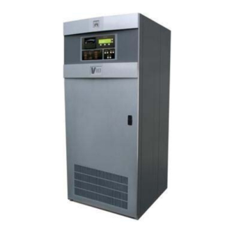
Table 1-3 provides a list of unique terms, special tools required to operate and abbreviations, and acronyms used in this maintain the transmitter. publication. Figure 1-1: V10/V7.5/V5/V3.5 FM Broadcast Transmitter V10/V7.5/V5/V3.5 Installation and Operation Manual Page 1-2 Issue 3.5 Section 1 General Information... -
Page 23: Recommended Site Test Equipment
NOMENCLATURE APPLICATION (EQUIVALENTS MAY BE USED) 50 Ω Dummy Load 'Off-air' testing Minimum power rating of 15,000 W (V10), 10,000 W (V7.5), 7,500 W (V5) or 5,000 W (V3.5) VSWR 1.1 (87.5 – 108 MHz) Digital Multimeter Testing and 3 1/2 digit, ac and dc volts (10 MΩ input), maintenance ohms and amps, ±0.5% accuracy, Fluke... -
Page 24: Glossary Of Terms
Static Random Access Memory Switching Power Refers to a module within the transmitter which supplies voltage to Supply (SPS) an RF power module. UART Universal Asynchronous Receiver-Transmitter V10/V7.5/V5/V3.5 Installation and Operation Manual Page 1-4 Issue 3.5 Section 1 General Information... -
Page 25: Preparation For Use And Installation
An air exchange rate of 1007 CFM (V10), 864 CFM (V7.5), 490 CFM (V5) or 431 NOTE CFM (V3.5) achieves acceptable intake/ Frequent reference is made to connectors exhaust temperature rise. -
Page 26: Work Area
Recommendations for Transmitter Site transients originating in the power source. Preparation booklet for specific protection Four toroids (Nautel Part # LP23) are techniques. Installing Nautel’s surge provided in the ancillary kit. A surge protection panel is highly recommended. -
Page 27: Transmitter Room Considerations
0.6 m (2 ft) ON LEFT- HAND SIDE TO OPEN FRONT DOOR No Right-Side Clearance Required MINIMUM 1.2 m (4 ft) Figure 2-1: Transmitter Room Considerations V10/V7.5/V5/V3.5 Installation and Operation Manual Page 2-3 Section 2 Preparation for Use and Installation Issue 3.5... -
Page 28: Customer Interface Connections
NX-LINK FERRITE TOROIDS V10/V7.5 SHOWN FOR REFERENCE (see Figure 2-3 for connection options) Figure 2-2: Customer Interface Connections V10/V7.5/V5/V3.5 Installation and Operation Manual Page 2-4 Issue 3.5 Section 2 Preparation for Use and Installation... -
Page 29: Ac Input Connection Options
220 - 240 V L-N (Line C) (Line B/ Neutral) (Line A) SINGLE-PHASE (1φ) (180 – 264 V ac) L-L or L-N Figure 2-3: Ac Input Connection Options V10/V7.5/V5/V3.5 Installation and Operation Manual Page 2-5 Section 2 Preparation for Use and Installation Issue 3.5... -
Page 30: Ac Wiring
The transmitter ancillary kit includes four 85.7 mm 2.2.9.1 Voltage Stability diameter toroids (Nautel Part # LP23). The ac power source’s nominal voltage must be maintained within the specified 2.2.6 Antenna/RF Output voltage range under all loading conditions. - Page 31 Observe local electrical codes when determining wire size and circuit breakers. Suggested wire sizes and breaker ratings based on maximum phase current for FM mode (25% over-capacity included). V10/V7.5/V5/V3.5 Installation and Operation Manual Page 2-7 Section 2 Preparation for Use and Installation...
-
Page 32: Power Consumption
Power consumption varies depending on are available (see below): the transmitter’s mode of operation (analog/hybrid/all-digital). If the transmitter V10/V7.5: 7/8 or 1-5/8 inch also available configuration is a dedicated analog, V5/V3.5: 7/8 or 3-1/8 inch also available hybrid, or all-digital transmitter, use Table 2.2.11 RF Drive Source(s) -
Page 33: External Interlocks
(minimum 100 ms) to input/output interface connections are ensure being sampled. See Table 2-3 or shown in Figure 2-7a (V10/V7.5) or 2-7b Figure 2-7a (V10/V7.5) or 2-7b (V5/V3.5) (V5/V3.5). The remote interface PWB for dc return (ground) locations. -
Page 34: On/Off Control
2.2.13.3 Main IPA Selection The main IPA selection circuit selects For V5/V3.5 transmitters, the remote which IPA (module for V10, PA for V5) is selection of the active IPA PA is enabled as the main IPA. It comprises an independent from the remote selection of A (TB3-7/8) and a B (TB3-9/10) circuit. -
Page 35: Main Ipa Power Supply Selection
[for FM+HD mode, 75 W (V10), 55 W (V7.5), 37 W (V5) or 27 W (V3.5); for HD mode, 30 W (V10), 20 W (V7.5), 15 W (V5) or 10 W (V3.5)]. V10/V7.5/V5/V3.5 Installation and Operation Manual... -
Page 36: Rf Monitor Samples
IPA Power Supply Status J4-23 Fan Supply Status J4-24 Transmitter, Mode, Power Valid Data Status J4-26 Monitor V10, FM, 10,000 W (250 W IPA) 1.0 V Ground J4-1,14,21,33,34,35 V10, FM+HD, 7,300 W 0.4 V Ac Fault Alarm J6-1 V10, HD, 2,800 W 0.4 V... -
Page 37: Forward Power Level Sample
The maximum sample voltage is the total power amplifier current is 360 A representative of the parameter’s full-scale (V10), 270 A (V7.5), 180 A (V5) or 135 A value (e.g., 12,000 W for V10 forward (V3.5). power; 9,000 W for V7.5 forward power;... -
Page 38: High Reflected Power Alarm
The same is true for +24 V. Its return must be connected to a GND terminal [see Figure 2-7a (V10/ V7.5) or V10/V7.5 transmitters except that the IPA 2-7b (V5/V3.5)] on the remote interface PWB. -
Page 39: Active Ipa Status
A logic false condition A status output that indicates which IPA is present when communication is lost. (Module for V10/V7.5, PA for V5/V3.5) is the active IPA is available on TB1-16 (IPA 2.2.17.10 +15 V Supply STATUS). A logic true condition is present A +15 V dc voltage for remote control/ when IPA 'B' is enabled as the active IPA. -
Page 40: Available Options
IPA source and an associated 2.2.21.8 Ac Power Surge Protector power supply. Panel Option Nautel can provide an ac power surge For V10/V7.5 transmitters, a standby IPA protector panel (Nautel Part # NAX188), module and associated IPA PS module to aid in protecting the transmitter from can be provided. -
Page 41: Installation
2.2 identifies all (a) Remove the packing bracket from of the remote controls and alarm/status each column (two for V10/V7.5, one outputs available. It is assumed that you for V5/V3.5; see Figure 2-6) of RF have reviewed this information and have power modules. -
Page 42: Removing Power Module Packing Bracket
QTY: 6 REMOVE EXISTING M4 SCREW FROM RF POWER MODULE AND REPLACE AFTER PACKING BRACKET IS REMOVED. Figure 2-6: Removing Power Module Packing Bracket V10/V7.5/V5/V3.5 Installation and Operation Manual Page 2-18 Issue 3.5 Section 2 Preparation for Use and Installation... -
Page 43: Installing Ac Power Wiring
1/8 inch (3.2 mm) of insulation from the end of (d) Get two ferrite toroids (Nautel Part # each wire. LP23, 85.7 mm) from the ancillary kit. V10/V7.5/V5/V3.5 Installation and Operation Manual... - Page 44 (j) Connect the ac ground wire to the inside threads of the station reference ground bolt (E1). (b) For M50 exciter(s), proceed to 2.3.7.1. For NE30 exciter(s), proceed to 2.3.7.2. V10/V7.5/V5/V3.5 Installation and Operation Manual Page 2-20 Issue 3.5 Section 2 Preparation for Use and Installation...
-
Page 45: M50 Exciter(S)
For IBOC operation only: Exciter RF wires from step (b) in a 37-pin D-sub sample BNC plug(s) (P71 for A14 and plug (Nautel Part # JS52, located in the P73 for A15, if used), and optional blank exciter kit) with the centre-... -
Page 46: Ne30 Exciter(S)
(exciter A) or J2 (exciter B) of RF (b) If the visible printing does not indicate drive splitter/changeover assembly the correct ac source voltage, A16 (see Figure MD-3 of the V10 or carefully withdraw it from the V5 Repair Manual). connector and re-insert it so that the •... -
Page 47: Installing Rf Feed Coaxial Cable
Use the It is important that this conductor does not M6 securing screws removed in contact the transmitter at any other point. step (b). V10/V7.5/V5/V3.5 Installation and Operation Manual Page 2-23 Section 2 Preparation for Use and Installation Issue 3.5... -
Page 48: Commissioning Procedures
IPA, IPA power supply and/or fan switching power supply module (A-H power supply may be duplicated and for V10, A-C and E-G for V7.5, A-D for connected to form main and standby V5, A-C for V3.5, IPA A and IPA B, if modules. -
Page 49: Initial Turn-On
Re-install covers when the preset and there should be no alarms commissioning procedure is complete. on the front panel System Diagram. V10/V7.5/V5/V3.5 Installation and Operation Manual Page 2-25 Section 2 Preparation for Use and Installation Issue 3.5... -
Page 50: Placing Transmitter On-Air
Select the sheet. Verify that the reflected power desired main exciter (A or B). indicated is less than 63 W (V10), 57 W (V7.5), 23 W (V5) or 16 W (V3.5) (t) If a standby fan PS is installed, select into a 50 Ω... - Page 51 A44J4 # IPA PS STATUS - # FAN PS STATUS - # VALID DATA STATUS - GROUND GROUND GROUND S2040058 VE Dimensions = mm (inches) External Input/Output Interface – V10/V7.5 Transmitter Issue 3.5 Not to Scale Figure 2-7a Page 2-27...
- Page 53 TRANSMITTER TRANSMITTER EXTERNAL EXTERNAL INPUT/OUTPUT INPUT/OUTPUT CONNECTIONS CONNECTIONS FROM 1-PHASE LINE A A1E1 RF OUTPUT TO ANTENNA SYSTEM # SMY ALARM - A42J6 AC POWER SOURCE # INTLK OPEN ALARM - (180-264 VAC) LINE B/NEUTRAL A1E2 # BATT/MEM FAIL ALARM - RF MONITOR TO EXTERNAL A42J3...
-
Page 55: Dimensional Information - V10/V7.5
Dimensions = inches (mm) Dimensional Information – V10/V7.5 Transmitter Issue 3.5 Not to Scale Figure 2-8 Page 2-29... -
Page 57: Dimensional Information - V5/V3.5
Dimensions = mm (inches) Dimensional Information – V5/V3.5 Transmitter Issue 3.5 Not to Scale Figure 2-9 Page 2-30... -
Page 59: Operating Instructions
RF power produced by the state). It is not possible to enable the RF power modules: power stages until all of the external interlock switches are closed. V10/V7.5/V5/V3.5 Installation and Operation Manual Page 3-1 Section 3 Operating Instructions Issue 3.5... -
Page 60: Electrostatic Discharge Protection
Electronic components should be stored in anti-static materials. 3.4.3 Tools/Test Equipment Testing and maintenance equipment, including soldering and unsoldering tools, should be suitable for contact with static sensitive semiconductor devices. V10/V7.5/V5/V3.5 Installation and Operation Manual Page 3-2 Issue 3.5 Section 3 Operating Instructions... -
Page 61: Front Panel
Off switch is functional regardless of local or remote selection. Refer to Figure 3-3 and Table 3-2 for a description of the controls and indicators. Figure 3-1: Transmitter Front Panel (Primary User Interface) V10/V7.5/V5/V3.5 Installation and Operation Manual Page 3-3 Section 3 Operating Instructions Issue 3.5... -
Page 62: Switching Power Supply Module
A30). System Diagram Exciter Output Network IPA/ Changeover Low Voltage Power Supply External Alarm AC Mains Power Supply Figure 3-2: Transmitter Front Panel – System Diagram Section V10/V7.5/V5/V3.5 Installation and Operation Manual Page 3-4 Issue 3.5 Section 3 Operating Instructions... -
Page 63: Front Panel - System Diagram Controls And Indicators
OR the forward power level has exceeded an acceptable level (while ALC is disabled) OR the forward power has been decreased below 1630 W (V10)/1223 W (V7.5)/815 W (V5)/ 612 W (V3.5) (due to SWR foldback) OR one of the combiner’s cooling fans has failed OR the power level or temperature in one of the hybrid combiner’s reject loads has exceeded an acceptable level. -
Page 64: Transmitter Front Panel - Control Section
Figure 3-3: Transmitter Front Panel – Control Section V10/V7.5/V5/V3.5 Installation and Operation Manual Page 3-6 Issue 3.5 Section 3 Operating Instructions... -
Page 65: Front Panel - Control Section Controls And Indicators
100 W (V10/V7.5) or 50 W (V5/V3.5). In hybrid (FM+HD) or all-digital (HD) mode each step increases the RF drive from the M50 exciter to achieve a power increase of 1% of the rated power. -
Page 66: Switching Power Supply Module - Front Panel
AC OK DC FAIL STANDBY Figure 3-4: Switching Power Supply Module – Front Panel V10/V7.5/V5/V3.5 Installation and Operation Manual Page 3-8 Issue 3.5 Section 3 Operating Instructions... -
Page 67: Switching Power Supply Module (Pa/Ipa) Controls And Indicators
PA ‘A’ or ‘B’ for V5/V3.5 transmitters NOTES: For V10 transmitters, there are up to ten identical switching power supply modules. Prefix with U1 (IPA ‘A’), U2 (IPA ‘B’) or U3 through U10 (PA ‘A’ through PA ‘H’ respectively) as applicable. -
Page 68: Control/Display Pwb A43 - Partial View
R310 R312 R307 C193 R279 R105 R311 TP18 C191 R106 R107 R108 M1980240 VA E7, E8 E2, E3, E10-E13 Figure 3-5: Control/Display PWB A43 – Partial View V10/V7.5/V5/V3.5 Installation and Operation Manual Page 3-10 Issue 3.5 Section 3 Operating Instructions... -
Page 69: Control/Display Pwb - Controls And Indicators
Jumpers single or balanced operation. Factory installed in BAL (balanced) E10 – E13 position (shorting pins 2 and 3) for V series transmitters. No user adjustment required. V10/V7.5/V5/V3.5 Installation and Operation Manual Page 3-11 Section 3 Operating Instructions Issue 3.5... -
Page 70: Interconnect Pwbs
OPEN M2040049 VA Figure 3-6: Interconnect PWBs NOTE: V10 transmitters use PWBs A17, A18 & A23 through A30 V7.5 transmitters use PWBs A17, A18, A23 through A25 & A27 through A29 V5 transmitters use only A17 and A23 through A26 V3.5 transmitters use only A17 and A23 through A25... -
Page 71: A Interconnect Pwb – Controls And Indicators
4-position dipswitch, which is set to configure and identify its interconnected module (see Table 3-5b for switch settings). For the V10, there are up to ten electrically identical interconnect PWBs [A17, A18 (optional) and A23 through A30] used in conjunction with IPA modules ‘A’... -
Page 72: B Interconnect Pwb – Transmitter Usage
PA B PA C V10/V5 PA D V10/V7.5 PA E V10/V7.5 PA F V10/V7.5 PA G PA H 0 – OPEN 1 – CLOSED X – NOT APPLICABLE V10/V7.5/V5/V3.5 Installation and Operation Manual Page 3-14 Issue 3.5 Section 3 Operating Instructions... - Page 73 This page intentionally left blank V10/V7.5/V5/V3.5 Installation and Operation Manual Page 3-15 Section 3 Operating Instructions Issue 3.5...
-
Page 74: Remote Interface Pwb A44
C120 C124 C137 C107 C121 -15V +15V R112 INTLK EXCTR A EXCTR B C110 C122 R113 M2040009 VA E1 – E21 Figure 3-7 Remote Interface PWB A44 V10/V7.5/V5/V3.5 Installation and Operation Manual Page 3-16 Issue 3.5 Section 3 Operating Instructions... -
Page 75: Remote Interface Pwb - Controls And Indicators
E21) shorts pins 2 and 3 of its associated 3-pin header. See Table 2-3 for specific jumper settings. Note that some jumpers are installed as part of spare circuitry (E5 and E19) and do not require configuration. V10/V7.5/V5/V3.5 Installation and Operation Manual Page 3-17 Section 3 Operating Instructions Issue 3.5... - Page 76 M1980247 VA Nautel Part # NAPI71A/01 variation shown; Nautel Part # 198-1025 is a modified version of the NAPI71A/01 that is used only for dual PA IPA modules in V5 and V3.5 transmitters. In this case, LEDs DS1 and DS2 are removed.
-
Page 77: Power Module Interface Pwb
This jumper is factory set in the BIAS position (shorting pins 1 and 2) and requires no adjustment in a V10/V7.5 transmitter. The jumper is factory set in the DUAL IPA position (shorting pins 2 and 3) for a dual PA IPA module in a V5/V3.5 transmitter. -
Page 78: Diagnostic Display
There are three soft- key push buttons whose functions are indicated by the text displayed directly above them for a given menu. V10/V7.5/V5/V3.5 Installation and Operation Manual Page 3-20 Issue 3.5 Section 3 Operating Instructions... -
Page 79: Flow Diagram - Diagnostic Display Menu Functions
** - Optional. Displayed only when required - should only be performed by NxLink is installed and trained personnel. communicating with transmitter. Figure 3-11 – Flow Diagram – Diagnostic Display Menu Functions V10/V7.5/V5/V3.5 Installation and Operation Manual Page 3-21 Section 3 Operating Instructions Issue 3.5... -
Page 80: View Faults
A preset can be edited without making it the menu. active preset. Pressing Select on a highlighted preset in the Power Control screen is the only way to activate a preset from the GUI. V10/V7.5/V5/V3.5 Installation and Operation Manual Page 3-22 Issue 3.5 Section 3 Operating Instructions... -
Page 81: View Rf Module Status And Fan Speed
(A - H and IPA modules A Preset screen for the active preset and will and B for V10 transmitters; A – C, E – G, and highlight the Power parameter. If Power - IPA modules A and B for V7.5 transmitters;... -
Page 82: View Events Log
Modules A - H and IPA modules A and B Log (using ) and press Select. for V10; A - C, E - G and IPA modules A A list of events (1 is the most recent) will and B for V7.5; A - D and IPA module for be displayed, sorted by date and time, V5;... -
Page 83: Select Metered Parameters
(a) From the main menu, highlight Meter **** denotes used only in V7.5 Presets (using ) and press ***** denotes used only in V10 Select. A list of possible metered parameters will be displayed (two at a • Forward Power time, in the default display order of the •... -
Page 84: Front Panel Metering/Setting Display Contrast
Edit. Use set the highlighted field. Press Save to update the setting. (c) Press Back to return to previous screen. V10/V7.5/V5/V3.5 Installation and Operation Manual Page 3-26 Issue 3.5 Section 3 Operating Instructions... -
Page 85: Change Hardware Settings
Back remote interface PWB A44 NOTE (c) Use to highlight either the Hardware settings are established at Nautel parameter or the scaling factor. Press during factory testing and recorded in the Edit. Critical Parameters sheet. User adjustments - which are not normally required - should •... -
Page 86: Calibrate Hd Pa And Ipa Voltages
Modifying factory settings (see Critical Calibrate Meters Calibrate Meters Parameters sheet) may void the equipment’s +2.5V Ref. +2.5V Ref. 2.50 V 2.50 V warranty. Contact Nautel prior to performing 3.00 3.00 these adjustments. Scaling: 4.011 E-1 Scaling: 4.011 E-1 Edit Edit... -
Page 87: Enable/Disable Setup Mode
If Disabled is displayed, setup and do not normally require adjustment. mode is enabled. The default mode is Contact Nautel prior to attempting to alter Disabled. Cycling of the ac power will these settings. Failure to comply could reset to default mode. -
Page 88: System Configuration
Back active preset as the transmitter) or Disable E-H (or E-G for V7.5) Rej Pwr High and O/P Rej Pwr High used in V10/V7.5 NOTE only. Display reads Unused for V5/V3.5. The preset synchronization feature only selects the M50’s preset. The associated 3.6.12.7 System Configuration... -
Page 89: Save/Recall Factory Settings
Changing from Analog to Digital mode, with the transmitter’s controller. the IPA Input Low threshold changes from 12 W to 6 W (V10/V7.5) or from 6 W to 11:26 98.10MHz 0.00kW 1 ExA IPAA/A FanA 11:26 98.10MHz 0.00kW 1 ExA IPAA/A FanA... -
Page 90: Set Main/Standby Operation
Main and Auto fields cannot be supply module and fan supply module is selected/edited. The main exciter, IPA optional. (V10/V7.5 only), IPA PA (V5/V3.5 only), IPA PS (V5/V3.5 only) and Fan PS will In V10/V7.5 transmitters, the entire IPA default to A. -
Page 91: Testing And Adjustment
(e.g., forward power, PA voltage, total PA current, etc.). All transmitter parameters, in combinations of three, may be displayed on this screen. See paragraph 3.6.8. V10/V7.5/V5/V3.5 Installation and Operation Manual Page 4-1 Section 4 Testing and Adjustment Issue 3.5... -
Page 92: Test Equipment Required
Critical Parameters sheet, taped to A dummy load, rated for a minimum of the tray in front of IPA module A 15,000 W for V10, 10,000 W for V7.5, (A19). For future reference, store 7,500 W for V5, 5,000 W for V3.5, and a... -
Page 93: Optionally Duplicated Modules
V5/V3.5 V10/V7.5 (V5 shown for reference) (V10 shown for reference) V5/V3.5 IPA MODULE Figure 4-1 Optionally Duplicated Modules V10/V7.5/V5/V3.5 Installation and Operation Manual Page 4-3 Section 4 Testing and Adjustment Issue 3.5... -
Page 94: Transmitter Turn-On
(e) The remote interface PWB's remote (d) The Refld Pwr (reflected power) on status pin (J4-22) and XMTR READY the GUI will be less than 63 W (V10), STATUS terminal (TB1-13) will be 57 W (V7.5), 23 W (V5) or 16 W current-sink-to-ground. -
Page 95: Remote Selection Of Active Exciter
TB3-3 (-)]. (k) All cooling air fans, except the standby (f) The RF output, as displayed by the RF IPA module’s fan (for V10 only), will KILOWATTS meter and GUI, will turn on. momentarily go to 0 W and then return to rated power. -
Page 96: Remote Selection Of Active Ipa Module Or Pa
(c) The RF output, as displayed by the RF (d) The GUI will indicate IPA B (and IPA KILOWATTS meter and GUI, will PS B for the V10/V7.5) is active. The momentarily go to 0 W and then return remote interface PWB’s IPA STATUS to rated power. -
Page 97: Remote Selection Of Fan Power Supply
KILOWATTS meter and GUI, will be (b) Remotely select preset 2 by activating the preset 5 level. an input to remote interface PWB's Ext Preset 2 pin(s) [J4-4 (+)/J4-5 (-)]. V10/V7.5/V5/V3.5 Installation and Operation Manual Page 4-7 Section 4 Testing and Adjustment Issue 3.5... -
Page 98: Remote Power Trim Control
PWB's Ext smaller steps [in FM mode, increment is Preset 6 pin(s) [J4-12 (+)/J4-13 (-)]. 100 W (V10/V7.5) or 50 W (V5/V3.5); in FM+HD or HD mode, increment is 1% of (o) The RF output, as displayed by the RF rated transmitter power (see 2.2.13.7)] until... -
Page 99: Remote Reset Control
(c) Enter the address from step (b) into the web browser’s address bar. The (a) Verify the prerequisites of 4.3.5.1 are transmitter’s remote diagnostic web complete and are being met. page should appear. V10/V7.5/V5/V3.5 Installation and Operation Manual Page 4-9 Section 4 Testing and Adjustment Issue 3.5... -
Page 100: Exciter Auto Changeover Check
In the GUI’s changeover menu, set changeover is initiated when a main exciter A as the main exciter (see (active) exciter fault occurs as follows: 3.6.13). The alarms should clear. V10/V7.5/V5/V3.5 Installation and Operation Manual Page 4-10 Issue 3.5 Section 4 Testing and Adjustment... -
Page 101: Ipa Auto Changeover Check
ON/STANDBY switch of IPA B’s If the transmitter has dual IPA modules (for switching power supply (U2) to standby V10/V7.5 transmitters) or a dual PA IPA (toggle down). A changeover to IPA module (for V5/V3.5 transmitters), verify an module A (and IPA PS B) shall occur. -
Page 102: Ipa Ps Auto Changeover Check
Power Supply alarm will turn on momentarily, the system diagram Changeover alarm will turn on, and the GUI will note the IPA PS V10/V7.5/V5/V3.5 Installation and Operation Manual Page 4-12 Issue 3.5 Section 4 Testing and Adjustment... -
Page 103: Improving Reject Load Power
• Swap A and C • Swap E and G • Swap C and G • Swap B and D (V10/V5 only) • Swap F and H (V10 only) • Swap E and H (V10 only) • Swap B and F •... -
Page 104: Changing Frequency
E4 (as applicable) of the ac distribution assembly. Ensure the ac terminals do not turn during wire installation. Retain any ferrite toroids used with the ac wiring. V10/V7.5/V5/V3.5 Installation and Operation Manual Page 4-14 Issue 3.5 Section 4 Testing and Adjustment... -
Page 105: System Level Troubleshooting
– open-air and symptoms to determine the corrective closed-air. Open-air systems contain two action required. Troubleshooting (V5/V3.5) or three (V10/V7.5) air filters information is presented based on the located in the back. For closed-air systems transmitter front panel’s diagnostic the user must supply the filters, which are information (see 5.5). -
Page 106: Corrective Maintenance
Replace the battery (3 V lithium, Nautel 5.3.1.1 Remote Troubleshooting Part # BBLT01, Vendor # CR2032) at Remote on-air troubleshooting consists of... -
Page 107: Local Troubleshooting
(rated at a minimum of air troubleshooting. 15,000 W for V10, 10,000 W for V7.5, 5.4 ELECTROSTATIC PROTECTION 7,500 W for V5, 5,000 W for V3.5) for off- air troubleshooting procedures. If an... -
Page 108: Handling/Storage
IPA should also occur. • The GUI’s main screen will indicate when a fault has occurred. Status is displayed above the centre soft key. V10/V7.5/V5/V3.5 Installation and Operation Manual Page 5-4 Issue 3.5 Section 5 System Level Troubleshooting... - Page 109 Table 5-2 is keyed to illuminated (red) front panel ‘System Diagram’ alarm lamps. Locate the offending alarm lamp(s) in Table 5-2 and then refer to the appropriate troubleshooting paragraph. V10/V7.5/V5/V3.5 Installation and Operation Manual Page 5-5 Section 5 System Level Troubleshooting Issue 3.5...
-
Page 110: Troubleshooting Guide
Mode/Freq Mismatch 5.5.1.6 5.5.2 IPA Shutdown 5.5.2 IPA Fwd High (V5/V3.5) or IPA Q3 Fwd High (V10/V7.5) or 5.5.2.1 IPA Q4 Fwd High (V10/V7.5) IPA Fwd Low (V5/V3.5) or IPA Q3 Fwd Low (V10/V7.5) or 5.5.2.2 IPA Q4 Fwd Low (V10/V7.5) IPA Match (V5/V3.5) or... - Page 111 Rej Pwr Shutdown 5.5.3.9 A-B Rej Ld Tmp High or B-C Rej Ld Tmp High (V7.5/V3.5) or C-D Rej Ld Tmp High (V10/V5) or 5.5.3.10 E-F Rej Ld Tmp High (V10/V7.5) or F-G Rej Ld Tmp High (V7.5) or G-H Rej Ld Tmp High (V10) Comb Top Fan Fail or 5.5.3.11...
-
Page 112: Exciter Alarm
NOTE systems or 6 W for V10/V7.5 and 3 W for V5/V3.5 for digitally configured systems If the alarm lamp is still on after each step, operating in FM mode]. This may be a the fault remains; continue troubleshooting result of an exciter fault, excessive load at the next paragraph. -
Page 113: Low Rf Drive
• stable and within acceptable limits Input High threshold is user definable, but [above 12 W (6 W) for analog is defaulted to 38 W for V10/V7.5 or 19 W configured V10/V7.5 (V5/V3.5) or 6 W for V5/V3.5 in FM mode; the threshold is (3 W) for digitally configured V10/V7.5... -
Page 114: Check Exciter
Check Exciter alarm. changeover to reserve IPA. Refer to the exciter’s technical manual for further information on the indicated V10 or V7.5, Single IPA Module: only the fault(s). faulty IPA PA [A19A3 (Q3) or A19A4 (Q4)] latches off. The remaining IPA PA Possible Associated Faults: continues to operate. -
Page 115: Ipa Forward High
RF drive PWB fault detection circuitry. input level. The associated Module Fail (A-H for V10; A-C, E-G for V7.5; A-D for (c) Before removing a switching power V5, A-C for V3.5) and associated switching supply module from the transmitter, power supply module PS Fail (A-H for V10;... -
Page 116: Ipa Forward Low
PWB (A23 - A30 alarm occurs when the IPA (specifically for V10, A23 - A25 and A27 - A29 for A3 or A4 in the V10/V7.5) peak forward V7.5, A23 - A26 for V5, A23 - A25 for power falls below the reference IPA volts V3.5). -
Page 117: Ipa Reflected High
(A21 or A22, as applicable), power module’s interconnect PWB (A23 the control/display PWB (A43) fault - A30 for V10, A23 - A25 and A27 - A29 detection circuitry, or the IPA module/ for V7.5, A23 - A26 for V5, A23 - A25 PA. -
Page 118: Module Offline
PWB [A17 (IPA A), A18 If the voltage is not between 47 V and (IPA B), A23 (A) - A30 (H) for V10; A17 53 V, check the voltage between (IPA A), A18 (IPA B), A23 (A) - A25 (C), E1 (+) and E2 (-) of the PS interface PWB [A2 (IPA A), A3 (IPA B, V10/V7.5... -
Page 119: Pa Failure
PA currents) is outputs and the combiner/filter inputs detected. Use these LEDs to isolate which [A41A1 - A41A4 for V10/V7.5 or A41A1 PA has failed on which RF power module. and A41A2 for V5/V3.5] for loose Troubleshoot as follows: connections or damage. -
Page 120: Output Network Alarm
103 W for V3.5 in FM mode; 197 W for RF power module. If the voltage is V10, 147 W for V7.5, 98 W for V5 or 73 W present, a wiring defect may exist. If no for V3.5 in FM+HD mode; 79 W for V10, voltage is present, check for a hot PTC 59 W for V7.5, 39 W for V5 or 29 W for... -
Page 121: Swr Shutdown
[SWR detection circuitry. Shutback threshold is user definable, but is defaulted to 1,200 W for V10, 900 W for Possible Associated Faults: V7.5, 600 W for V5 or 450 W for V3.5, for - SWR Shutdown all modes]. -
Page 122: Low Forward Power
- Low Fwd Pwr 5.5.3.8 Reject Load Power Shutback 5.5.3.7 High Reject Load Power and An A-D Rej Ld Shutback (V10/V5), A-C Reject Power Foldback Rej Ld Shutback (V7.5/V3.5), E-H Rej Ld A High Rej Pwr alarm occurs when any of Shutback (V10), E-G Rej Ld Shutback the transmitters reject loads’... -
Page 123: Reject Load Power Shutdown
FM+HD and HD modes; (a) Check for fan blockage. If the fan is 1500 W (V10), 1120 W (V7.5), 750 W (V5) functioning (compared to other fans), or 560 W (V3.5) for FM mode, and the but the indicated speed is zero (see High Temp Latch alarm will be displayed. -
Page 124: Low Voltage Power Supply Alarm
U11 and U12 for dual LVPS transmitters) fail, resulting in an out-of- tolerance dc power supply voltage(s) (+5 V, +15 V, or -15 V). Troubleshoot an LVPS Fault as follows: V10/V7.5/V5/V3.5 Installation and Operation Manual Page 5-20 Issue 3.5 Section 5 System Level Troubleshooting... -
Page 125: Fan Ps Fail And Replacement
Log will indicate a Low Ac Alarm on the ac and press RF On. occurred. (e) Adjust the replacement fan PS module’s potentiometer one turn counter-clockwise. V10/V7.5/V5/V3.5 Installation and Operation Manual Page 5-21 Section 5 System Level Troubleshooting Issue 3.5... -
Page 126: Low Ac Alarm
A Low Ac Alarm occurs when the ac Fail input voltage is below the switching power A PS Fail (A-H for V10, A-C, E-G for supplies’ internal threshold or one of the V7.5, A-D for V5 or A–C for V3.5) or IPA... -
Page 127: Backup Battery Low Alarm
Exciter (see 5.5.1) alarm to troubleshoot. - PS Fail A - PS Fail D as applicable - PS Fail E - PS Fail H (V10/V7.5) as applicable - IPA PS Fail A or B V10/V7.5/V5/V3.5 Installation and Operation Manual... -
Page 128: External Alarms
NOTE 5.5.8 External Alarms In a V10/V7.5, an IPA changeover affects both the IPA module and its associated IPA 5.5.8.1 Interlock Open Alarm PS (i.e., they are ganged together). In a An Interlock Open alarm occurs if the V5/V3.5, however, the IPA PA and IPA PS transmitter interlock is open. -
Page 129: Operation With Defective Or Missing
The top combiner fan (B11) is attached to components due to the failure, i.e., reject load assembly A39. The bottom power reduction. combiner fan (B12) is attached to reject load assembly A40. V10/V7.5/V5/V3.5 Installation and Operation Manual Page 5-25 Section 5 System Level Troubleshooting Issue 3.5... -
Page 130: Power Modules(S)
RF power modules from a specific to 77% of its desired power level with one pair are removed (e.g., for a V10: modules module removed, or up to 56% with two A and B, C and D, E and F, or G and H). - Page 131 Table 5-3a: V10 - Output Power Level vs. Module Failure/Removal RF Output Power PA/Module (% of original RF output power) Failures/ Removal Best Case Worst Case 1 PA 2 PAs 3 PAs 1 Module 2 Modules Table 5-3b: V7.5 - Output Power Level vs. Module Failure/Removal...
-
Page 132: Replacing An Rf Power Module
Refer to right-hand column contains - from top to paragraph 5.9.2 to install an RF power bottom - RF power modules E-H (V10) or module. Refer to the Repair manual to E-G (V7.5) and IPA module B, if troubleshoot and/or repair a defective RF applicable. -
Page 133: Rf Power Module Installation
5.10 IPA MODULE FAULT ISOLATION Install an operational RF power module in the transmitter as follows: Determine if an IPA module (V10/V7.5) or IPA PA (V5/V3.5) is defective, as follows: (a) Lift the operational RF power module NOTE into the transmitter and onto its support tray. -
Page 134: Replacing An Ipa Module
5.11.1 IPA Module Removal power module interface PWB – A5). Remove a defective IPA module from the transmitter as follows: (b) For V10/V7.5 or dual IPA V5/V3.5 transmitters, disconnect the following (a) Verify the requirements of paragraph connections on the power module 5.11 have been completed. -
Page 135: Ipa Module Installation
PA #2, PA #3, and therefore J1, J2, J3, drive source. A5DS1, A5DS2, and A5DS3 are no longer applicable with respect to the IPA replacement module. V10/V7.5/V5/V3.5 Installation and Operation Manual Page 5-31 Section 5 System Level Troubleshooting Issue 3.5... -
Page 136: Reject Load Module Removal
The reject load module is heavy. Ensure Retain the securing hardware [12 adequate manpower is available when (V5/V3.5) or 14 (V10/V7.5) M5 Phillips installing it in the transmitter. screws]. V10/V7.5/V5/V3.5 Installation and Operation Manual Page 5-32 Issue 3.5... -
Page 137: Rf Drive Splitter/Changeover Removal
(b) Reverse the order of steps in For V10 transmitters, reject load PWB paragraph 5.12.1. A39A2 accepts all PA outputs of RF power modules E and F and applies them NOTE to combiner A41A3. For V7.5 transmitters, Coaxial cables W51-W82 (V10), W51- reject load PWB A39A2 accepts all PA W62, W67-W78 (V7.5), W51-W66 (V5),... -
Page 138: Ipa Splitter Removal
5.13.2 to install an RF drive splitter/changeover assembly. Refer to the Remove a defective IPA splitter assembly Repair manual to troubleshoot or repair a (A21 or – for V10/V7.5 transmitters – A22) defective RF drive splitter/changeover from the transmitter as follows: assembly. -
Page 139: Printed Wiring Board (Pwb) Replacement
IPA splitter assembly: All coaxial cables and plugs have tags near their connectors indicating their A21 - A-D (V10/V5) or A-C (V7.5/V3.5): designation and mating information. Use Disconnect coaxial cables W11P1- these tags and the labels on the assembly... -
Page 140: Control/Display Pwb Replacement
PWB connectors. The spares kit, if (b) Verify preset parameters and purchased, contains a tool (Nautel Part # thresholds are as desired. HAS69, Vendor # DMC DRK38) for this purpose. Contact Nautel before attempting (c) Verify Meter Scale Factors are equal to to replace an interconnect PWB. -
Page 141: Low Power Operation For Antenna Maintenance
STANDBY (toggle down) until the desired power is achieved. V10/V7.5/V5/V3.5 Installation and Operation Manual Page 5-37 Section 5 System Level Troubleshooting Issue 3.5...
Need help?
Do you have a question about the V10 and is the answer not in the manual?
Questions and answers