
Related Manuals for Nautel VX Series


Summary of Contents for Nautel VX Series
- Page 1 1: INSTALLATION MANUAL FM B ROADCAST RANSMITTER Document ID: NHB-VX3-VX6-INS Version: Issue Date: 2023-08-16 Status: Standard...
- Page 3 For verification of materials, the reader is encouraged to consult the respective manufacturer's most recent publication on the official website or through contact with Customer Service. © Copyright 2023 NAUTEL. All rights reserved. VERSION 1.0 2023-08-16 PAGE III...
- Page 5 10089 Peggy’s Cove Road Hackett’s Cove, NS B3Z 3J4 Canada declare under our sole responsibility that the product: Product Name: VX Series FM Transmitter Model Number: to which this declaration relates, is in conformity with the following standards and/or technical specifications: Safety (3.1a):...
- Page 6 10089 Peggy’s Cove Road Hackett’s Cove, NS B3Z 3J4 Canada declare under our sole responsibility that the product: Product Name: VX Series FM Transmitter Model Number: VX3.5 to which this declaration relates, is in conformity with the following standards and/or technical specifications: Safety (3.1a):...
- Page 7 10089 Peggy’s Cove Road Hackett’s Cove, NS B3Z 3J4 Canada declare under our sole responsibility that the product: Product Name: VX Series FM Transmitter Model Number: to which this declaration relates, is in conformity with the following standards and/or technical specifications: Safety (3.1a):...
- Page 8 10089 Peggy’s Cove Road Hackett’s Cove, NS B3Z 3J4 Canada declare under our sole responsibility that the product: Product Name: VX Series FM Transmitter Model Number: to which this declaration relates, is in conformity with the following standards and/or technical specifications: Safety (3.1a):...
- Page 9 10089 Peggy’s Cove Road Hackett’s Cove, NS B3Z 3J4 Canada declare under our sole responsibility that the product: Product Name: VX Series FM Transmitter Model Number: to which this declaration relates, is in conformity with the following standards and/or technical specifications: Safety (3.1a):...
-
Page 11: Table Of Contents
VX3 TO VX6 INSTALLATION MANUAL TABLE OF CONTENTS CONTENTS Contact Information 1.iii Release Control Record 1.ix About This Manual Technical Support 1.xi VX Series Transmitter Manuals 1.xi Nautel Website / Online Resources 1.xii About Safety 1.xv Electrical Hazards 1.xv Lightning Hazards 1.xvi RF Hazards 1.xvi... - Page 12 VX3 TO VX6 INSTALLATION MANUAL TABLE OF CONTENTS Pre-installation tasks 1.2.1 Preparing for Installation 1.2.1 Selecting a Location for the Transmitter 1.2.2 Physical Requirements 1.3.1 Dimensions and Weights 1.3.1 Clearances 1.3.1 Cooling requirements 1.4.1 Air Flow in the Transmitter 1.4.1 Cooling 1.4.2 Heating...
- Page 13 Going On-Air 1.11.4 Network Setup 1.11.5 Parts and Tools 1.12.1 Contacting Nautel 1.12.1 Parts Supplied by Nautel 1.12.2 Parts Not Supplied by Nautel 1.12.2 Parts Ordering 1.12.2 Module Exchange Program 1.12.3 Tools for Installation 1.12.3 VERSION 1.0 2023-08-16 PAGE VII...
- Page 14 VX3 TO VX6 INSTALLATION MANUAL TABLE OF CONTENTS Pre-Installation / Installation Assistance 1.13.1 Pre-Installation Consulting 1.13.1 Installation and Commissioning Service 1.13.1 Online Documentation 1.13.2 On-Site Support 1.13.3 Training 1.13.3 Standard Warranty 1.13.4 Extended Warranties 1.13.7 List of terms 1.14.1 PAGE VIII VERSION 1.0 2023-08-16...
-
Page 15: Release Control Record
VX3 TO VX6 INSTALLATION MANUAL Release Control Record ISSUE DATE REASON 2023-08-16 Release 1.0 for VX high power models. Supports hardware versions: VX3, VX3.5 and VX4 (NARF82) VX5, VX6 (NARF83) Supports software version VX SW 6.2 and later. VERSION 1.0 2023-08-16 PAGE IX... - Page 16 VX3 TO VX6 INSTALLATION MANUAL PAGE X VERSION 1.0 2023-08-16...
-
Page 17: About This Manual
About This Manual Technical Support Nautel offers technical support to customers over the Internet and by telephone. Nautel’s customer support team will answer your questions and work with you to identify and resolve problems. For 24-hour technical support, call toll free at 1.877.628.8353 (in USA and Canada only) or call 1.902.823.5100 (international) or find us on the Internet at http://www.nautel.com. -
Page 18: Nautel Website / Online Resources
VX3 TO VX6 INSTALLATION MANUAL Nautel Website / Online Resources The Nautel website provides useful resources to keep you up to date on your VX series transmitter. Frequently asked questions (FAQ), How To Videos, latest software versions are just a few of the many resources available. - Page 19 VX3 TO VX6 INSTALLATION MANUAL Online Documentation The Technical Documentation section of the Nautel Support website provides online access to all the documentation for your VX series transmitter. Documentation is provided in Acrobat (PDF) format. You can use the documentation online or print the sections that you need.
- Page 20 VX3 TO VX6 INSTALLATION MANUAL PAGE XIV VERSION 1.0 2023-08-16...
-
Page 21: About Safety
VX3 TO VX6 INSTALLATION MANUAL About Safety All Nautel transmitters are designed to meet the requirements of EN60215, Safety Requirements for Radio Transmitters. The philosophy of EN60215 is that the removal of any cover or panel that can only be opened using a tool is a maintenance activity, and that any person performing a maintenance activity is expected to be trained for that activity. -
Page 22: Lightning Hazards
VX3 TO VX6 INSTALLATION MANUAL Lightning Hazards Before opening the transmitter and touching internal parts, remove and solidly ground the antenna connection. WARNING: It is not enough to ground the antenna terminal with the antenna still connected. Even a small impedance in the ground strap will result in lethal voltages during a lightning strike. -
Page 23: Safety Precautions
Personnel must be familiar with the transmitter, so that they can avoid physical danger, and be aware of hazards to themselves and the equipment. Nautel offers a number of training courses covering the basic fundamentals of RF systems and transmitters, and the operation and maintenance of the transmitter. For more information about available courses and schedules, go to the Nautel website at http://support.nautel.com/training/, or ask... -
Page 24: Site Safety
Operation of safety interlocks (if installed) First Aid Nautel does not offer first aid training, since the hazards associated with high voltage and RF energy are not specific to the transmitter. However, the customer should provide first aid training to all personnel who have access to the transmitter site. - Page 25 VX3 TO VX6 INSTALLATION MANUAL Ac Power Protection You should take steps to protect equipment from surges (over-voltage spikes) on the ac power lines. Surges may occur during thunderstorms, or because of malfunctions in the electrical distribution grid. Surge suppressors and ac power conditioners can prevent serious damage to your on-site equipment, including the transmitter.
-
Page 26: Equipment Safety
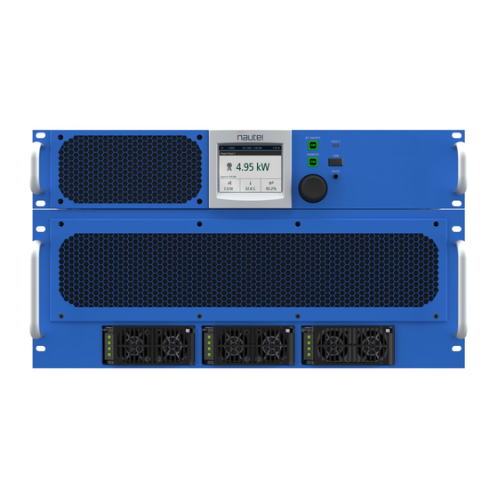
(and to protect the rest of your site equipment and your personnel). For detailed information about lightning protection, see the Nautel Site Preparation Manual on the provided documentation USB, or online from the Nautel website. Physical Protection Consider physical hazards to equipment at your site, including the transmitter. - Page 27 VX3 TO VX6 INSTALLATION MANUAL DESCRIPTION SECTION 1.1: DESCRIPTION This section provides a basic description of the VX3 to VX6 transmitters and includes the following topics: Overview Capabilities - see page 1.1.2 Transmitter Configuration - see page 1.1.3 Options - see page 1.1.4 Overview The VX3 to VX6 transmitter consists of two separate units - the exciter/controller assembly (top) and the amplifier assembly (bottom) (see...
-
Page 28: Description
VX3 TO VX6 INSTALLATION MANUAL DESCRIPTION Capabilities Power The VX3 to VX6 transmitters are solid-state, VHF, frequency modulated broadcast transmitters. See Table 1.1.1 for continuous RF output power capability, noting the maximum VSWR limitations for rated and maximum power. Table 1.1.1: VX3 to VX6 Power Capability RATED POWER (W) MINIMUM POWER MAXIMUM POWER (W) -
Page 29: Transmitter Configuration
1-5/8 inch EIA (standard) 18-53 V dc Nautel Part # VX3.5 1-5/8 to 7/8 inch EIA adapter (optional) (Nautel Part # UG132) NAPI201/01 320-460 V ac, 3 phase 185-265 V ac, 1 or 3 phase 1-5/8 inch EIA (standard) 23-65 V dc... - Page 30 RF Output Connector Nautel can provide a 1-5/8 to 7/8 inch EIA adapter to accommodate a 7/8 inch RF coaxial cable. Audio Processor The transmitter can be upgraded with an internal audio processor, available from Nautel (Nautel part # 235-5575), which is mounted on a tray inside the exciter/controller assembly.
-
Page 31: Pre-Installation Tasks
Refer to the Lightning Protection section of Nautel’s Recommendations for Transmitter Site Preparation Manual Install the ac power service into the planned transmitter location, and select a location for the ac surge protection panel (if purchased) near the transmitter. -
Page 32: Selecting A Location For The Transmitter
VX3 TO VX6 INSTALLATION MANUAL PRE-INSTALLATION TASKS Order any accessories or optional equipment that you may need. Typical requirements include: Tools - screwdrivers, nut drivers, etc. (see Parts and Tools, on page 1.12.1 for further details). Test equipment - digital multimeter. Peripheral equipment - PC or laptop, LAN/network connection, etc. -
Page 33: Physical Requirements
VX3 TO VX6 INSTALLATION MANUAL PHYSICAL REQUIREMENTS SECTION 1.3: PHYSICAL REQUIREMENTS This section provides physical specifications for the VX3 to VX6 transmitter and its components, and lists physical site requirements. Dimensions and Weights Dimensions and weights for the VX3 to VX6 transmitter are shown in Table 1.3.1. - Page 34 VX3 TO VX6 INSTALLATION MANUAL PHYSICAL REQUIREMENTS PAGE 1.3.2 VERSION 1.0 2023-08-16...
-
Page 35: Cooling Requirements
VX3 TO VX6 INSTALLATION MANUAL COOLING REQUIREMENTS SECTION 1.4: COOLING REQUIREMENTS This section provides information about heating and cooling requirements for the VX3 to VX6 transmitter site. Topics in this section include: Air Flow in the Transmitter Cooling - see page 1.4.2 Heating - see page 1.4.2 Air Flow in the Transmitter The VX3 to VX6 transmitter draws air in through the front, and exhausts air through the rear. -
Page 36: Cooling
VX3 TO VX6 INSTALLATION MANUAL COOLING REQUIREMENTS Cooling Do not allow the transmitter room ambient air temperature to exceed 50°C (122°F) at sea level. Cooler temperatures are recommended in order to improve the reliability of the transmitter. The transmitter will shutback its output power to 0 W if the intake temperature exceeds 55°C (131°F) and will recover automatically when the intake temperature reduces below 50°C (122°F). -
Page 37: Electrical Requirements
AC power for the exciter/controller assembly enters through a IEC 60320, C14 type connector on its rear panel. In the ancillary kit, Nautel provides a mating line cord (Nautel part # JN25) for 120 V ac power sources, and a mating connector (Nautel part # JDP48) with 3-terminal connections (accepts 14 to 18 AWG) for 220 V ac power sources. - Page 38 VX3 TO VX6 INSTALLATION MANUAL ELECTRICAL REQUIREMENTS Power Consumption and Typical Line Currents The input power requirement for the VX3 to VX6 is shown in Table 1.5.1. Use Table 1.5.1 to determine the maximum line current and maximum inrush current values for a given ac supply voltage. Choose wire sizes for the amplifier assembly’s ac input that are suitably rated.
-
Page 39: Station Reference Ground
Nautel recommends adding a bi-directional surge protector between the service entrance and the transmitter. A surge protector panel containing suitably rated varistors is available from Nautel. If purchased, install the surge protector panel close to the station reference ground, and as close as possible to the ac service entrance. - Page 40 VX3 TO VX6 INSTALLATION MANUAL ELECTRICAL REQUIREMENTS PAGE 1.5.4 VERSION 1.0 2023-08-16...
-
Page 41: Rf Output Requirements
The antenna feed line interconnecting the transmitter and the antenna system should be a suitably rated coaxial cable. The RF output is configured, by default, to accept a male 1-5/8 inch EIA connection. An optional 1-5/8 to 7/8 inch adapter is available (contact Nautel Sales), which provides a male 7/8 inch EIA connection. - Page 42 VX3 TO VX6 INSTALLATION MANUAL RF OUTPUT REQUIREMENTS PAGE 1.6.2 VERSION 1.0 2023-08-16...
-
Page 43: Program Inputs
VX3 TO VX6 INSTALLATION MANUAL PROGRAM INPUTS SECTION 1.7: PROGRAM INPUTS IMPORTANT! The transmitter’s USB ports are not designed to act as charging ports. The VX3 to VX6’s exciter/controller assembly accepts a variety of analog and digital program inputs. This section describes the requirements associated with the audio feeds to the transmitter. All VX3 to VX6 - Program connections are made at the rear of the exciter/controller assembly (see Input Connections on page... -
Page 44: Digital Inputs
XLR connectors (110 ohm balanced; support sample rates between 32 to 192 kHz). Connect (+) to pin 2, (-) to pin 3 and shield to pin 1 on the XLR connectors. The VX series transmitter's remote AUI or front panel UI allows for configuration of the audio input mode (left, right or stereo) and level (in dBfs). - Page 45 VX3 to VX6 Installation Manual AES/EBU 10 MHz 1 PPS MPX/SCA ANALOG 19 kHz 1 and 2 1 and 2 AUDIO L and R Connector, Input/Output Specifications Type/Gender ANALOG AUDIO L and R Balanced left/right 30 Hz to 15 kHz; adjustable between -12 to +12 dBm (nominal 0 dBm for ±75 kHz XLR, female composite input deviation, 600 ohm input impedance...
-
Page 46: Control And Monitor Wiring
VX3 TO VX6 INSTALLATION MANUAL CONTROL AND MONITOR WIRING SECTION 1.8: CONTROL AND MONITOR WIRING This section describes the types of control and monitoring for the VX3 to VX6. All connections are made VX3 to VX6 - Control/Monitor Connections on to the rear panel of the transmitter (see page 1.8.11). -
Page 47: Remote Inputs
(see Connections on page 1.8.11), which allow you to remotely control various operational characteristics of the transmitter. Each input is factory set to a control at Nautel, but they are user-configurable using the remote AUI. Table 1.8.1 on page 1.8.3 for a list of the preset inputs, their default functional descriptions and their associated pins on the REMOTE I/O-A, 9 -pin female D-sub connector. - Page 48 VX3 TO VX6 INSTALLATION MANUAL CONTROL AND MONITOR WIRING When the remote input is configured for logic ‘0’, a negative logic (current-sink-to-ground) command must be applied to the appropriate remote input (1 through 7). To avoid a ground loop, obtain the ground from pin 7).
-
Page 49: Remote Outputs
Nautel provides a D-sub mating connector (Nautel Part # JS223) and connector shell (Nautel Part # JS225) in the ancillary kit to facilitate customer connections to the controller, as applicable. The JS223 connector accepts 24-30 AWG wire. - Page 50 VX3 TO VX6 INSTALLATION MANUAL CONTROL AND MONITOR WIRING Table 1.8.2: Factory Defined Remote Outputs DEFAULT REMOTE PIN OF OUTPUT FUNCTION OUTPUT # REMOTE I/O-B (CHANNEL) Indicates the on/off status of the transmitter’s RF power stage. By default, RF On Status the output is low (current-sink-to -ground) when RF is on (enabled) and high (open collector) when RF is off (disabled).
-
Page 51: Analog Outputs
Nautel provides a D-sub mating connector (Nautel Part # JS223) and connector shell (Nautel Part # JS225) in the ancillary kit to facilitate customer connections to the controller, as applicable. The JS223 connector accepts 24-30 AWG wire. -
Page 52: Web Based Aui Control
The customer’s browser must support HTML5 to view the remote AUI. For security purposes, Nautel recommends you place your transmitter behind a firewall router. To allow remote AUI access to a transmitter behind a firewall, the firewall must allow TCP traffic through the... -
Page 53: Snmp Control/Monitoring
SNMP Agent Port number, Read Community and Write Community passwords and SNMP Trap information. If you are planning to use SNMP, contact Nautel to obtain MIB files for your client software or are available through Nautel’s FTP site: ftp://www3.nautel.com/SNMP_MIBs/... -
Page 54: External Interlock
It must present an open circuit when any interlock switch is activated and the RF output should be inhibited. A mating connector (Nautel part # JR52) and shorting jumper (Nautel part # JB56) are supplied with the transmitter to facilitate this connection. - Page 55 VX3 TO VX6 INSTALLATION MANUAL CONTROL AND MONITOR WIRING PAGE 1.8.10 VERSION 1.0 2023-08-16...
- Page 56 Provides a (-44 dB, typical) sample output, relative to the RF drive level. Intended for troubleshooting purposes only. EXTERNAL INTERLOCK (INTLK) Mating connector (Nautel part # JR52) and Jumper (Nautel part # JB56), pre-installed on transmitter. Spare connector and jumper located in the ancillary kit.
-
Page 57: Unboxing And Mounting The Transmitter
VX3 to VX6 transmitter assemblies (exciter/controller and amplifier assemblies), the VX3 to VX6 Quick Start Guide, VX Series USB (contains technical manual set, Unboxing and First Time Setup videos) and ancillary kit. -
Page 58: Mounting The Transmitter
Unless otherwise specified, all hardware referenced in the Unpacking/Installation video or the NOTE VX3 to VX6 Quick Start Guide is included in the VX3 to VX6’s ancillary kit (Nautel Part # 235-8554). Figure 1.9.1: Mounting Exciter/Controller and Amplifier Assemblies in a Rack... -
Page 59: Completing External Connections
NOTE commission your transmitter. If you used the Quick Start Guide to successfully commission your transmitter, Nautel recommends you use the information in this Installation Manual to verify your installation or for more in depth information, as required. Connecting Transmitter Cableset... -
Page 60: Connecting Ac Power
VX3 TO VX6 INSTALLATION MANUAL COMPLETING EXTERNAL CONNECTIONS Connecting Ac Power To connect ac power to the transmitter, perform the following steps: WARNING! ENSURE THAT WIRING SIZES ARE APPROPRIATE. AC WIRING MUST BE INSTALLED BY A QUALIFIED, LOCALLY-CERTIFIED ELECTRICIAN. DANGER! ENSURE AC POWER IS DISCONNECTED AND LOCKED OUT AT THE SOURCE BEFORE PROCEEDING. - Page 61 VX3 TO VX6 INSTALLATION MANUAL COMPLETING EXTERNAL CONNECTIONS Figure 1.10.2: Ac Entrance Drawer Slide showing terminal blocks Ac line connections Cable clamp screws Partial rear view of amplifier assembly Loosen the two (2) screws on the amplifier assembly’s conduit clamp (see Figure 1.10.2).
- Page 62 Push in the drawer slide and reattach the ac cover to the rear panel using the two (2) retained M4 screws. 10. Obtain a clip-on ferrite (Nautel part # LX70) from the ancillary kit and install over the customer provided ac cable, in close proximity to the ac entrance cover.
-
Page 63: Connecting Station Reference Ground
For information about grounding the lightning protection, see the Lightning Hazards, on page 1.1.xvi. For detailed information about lightning protection, see Nautel’s Recommendations for Transmitter Site Preparation Manual, available on the USB documentation provided with the transmitter or online from the Nautel website. -
Page 64: Installing And Connecting The Rf Feed Cable
Prepare and install an RF feed coaxial cable as follows: WARNING! ENSURE THAT AC POWER IS NOT BEING APPLIED TO THE TRANSMITTER DURING THIS PROCEDURE. Nautel recommends that you perform the commissioning procedure in Section 1.11, NOTE , which connects the transmitter to a dummy load, before connecting the transmitter “Commissioning”... -
Page 65: Connecting Remote Control/Monitor Wiring
Route all remote control/monitor cables to the rear panel of the exciter/controller assembly. Obtain two ferrite toroids (Nautel Part # LXP38, 19 mm inner diameter) from the ancillary kit. Pass all remote control and monitor cables through the ferrite toroids obtained in Step 3. - Page 66 VX3 TO VX6 INSTALLATION MANUAL COMPLETING EXTERNAL CONNECTIONS PAGE 1.10.8 VERSION 1.0 2023-08-16...
- Page 67 90-265 V ac, single phase, 47-63 Hz, Mating connector (Nautel part # JR52) and Jumper (Nautel part # JB56), pre-installed Connect the provided ac line cord (Nautel part # JN25) or equivalent). on transmitter. Spare connector and jumper located in the ancillary kit.
-
Page 68: Commissioning
VX3 TO VX6 INSTALLATION MANUAL COMMISSIONING SECTION 1.11: COMMISSIONING WARNING! Before applying ac power and turning on the transmitter, you must customize some circuits to the station's power source and operating requirements. Do not perform this pre-commissioning unless you are a station engineer or a competent electronics technician. -
Page 69: Pre-Commissioning Tasks
RF output stages and the antenna system if the transmitter is turned on. Ensure the external interlock is closed. Nautel ships the VX3 to VX6 with an external interlock mating connector and jumper (Nautel part # JR52/JB56) that has a short circuit between the two contacts. -
Page 70: Commissioning
Perform the steps outlined in the VX3 to VX6 Quick Start Guide (found in the shipping box) or the Unboxing and First Time Setup videos (found on the VX Series USB) for details on setting up the initial preset when the transmitter is turned on for the first time. -
Page 71: Going On-Air
VX3 TO VX6 INSTALLATION MANUAL COMMISSIONING Going On-Air WARNING! If a jumper is placed between the INTLK inputs on the rear panel of the transmitter, safety features controlled by the external interlocks will be disabled. A fail-safe method of alerting personnel to this fact should be implemented. -
Page 72: Network Setup
COMMISSIONING Network Setup CAUTION! When connecting to a Nautel transmitter, we support both HTTP and HTTPS protocols. If using HTTP, the data traffic is not encrypted, meaning your username/password could be compromised. For security reasons, Nautel recommends using HTTPS whenever possible. - Page 73 VX3 TO VX6 INSTALLATION MANUAL COMMISSIONING Figure 1.11.1: Network Settings screen All IP addresses shown are for reference purposes only MAC Address: Set during factory testing; cannot be modified DHCP or Static IP: Set to DHCP if your network has a DHCP server. Automatically assigns IP, netmask, gateway and nameservers.
-
Page 74: Parts And Tools
Module Exchange Program - see page 1.12.3 Tools for Installation - see page 1.12.3 Contacting Nautel You can reach Nautel to order parts or for technical assistance at: Nautel Limited 10089 Peggy’s Cove Road Hackett’s Cove, NS Canada B3Z 3J4 Phone: +1.877.628.8353 (Canada/US) -
Page 75: Parts Supplied By Nautel
See “VX3 to VX6 Transmitter Manuals” in the “About this Manual” section. Parts Not Supplied by Nautel Some parts and materials required to complete installation are not supplied by Nautel. The parts you need vary with the installation requirements. The list of parts you normally provide yourself during... -
Page 76: Module Exchange Program
May not be applicable to all customers. The replacement module is shipped to the customer as soon as the customer reports the failure. The customer then returns the failed module to Nautel using the same shipping package. - Page 77 VX3 TO VX6 INSTALLATION MANUAL PARTS AND TOOLS PAGE 1.12.4 VERSION 1.0 2023-08-16...
-
Page 78: Pre-Installation / Installation Assistance
Extended Warranties - see page 1.13.7 Pre-Installation Consulting Nautel field support specialists are available to answer questions and work with you to ensure that your site will be ready for the installation of your VX3 to VX6 transmitter. For support, contact Nautel... -
Page 79: Online Documentation
Frequency counter test load (rated for 150% of carrier power, VSWR less than 1.1:1) Nautel’s service representative takes full responsibility for commissioning the transmitter, validating all external interfaces (i.e., the ac supply, RF output, remote control and monitoring equipment) and checking out the equipment prior to activation. -
Page 80: On-Site Support
Nautel training programs are made up of individual modules that can be 'mixed and matched' to meet the customer’s specific training needs. All Nautel training courses are available at the Nautel Training Centre. -
Page 81: Standard Warranty
If the Buyer receives a replacement module, as part of Nautel's module exchange program, the old module must be returned to Nautel within 30 days of receipt of the new module, at the buyers expense. If the old module is not received after 30 days, the customer will be invoiced. The buyer is responsible for installing the replacement/repaired module in the transmitter. - Page 82 Nautel shall have the right and shall be provided full access to investigate whether failures have been caused by factors beyond its control. 10. In no event shall Nautel be liable for any consequential damages arising from the use of this equipment.
- Page 83 Module Exchange Service In order to provide Nautel customers with a fast and efficient service in the event of a problem, Nautel provides - for North American customers only - a factory rebuilt, module exchange service which takes full advantage of the high degree of module redundancy in Nautel equipment. May not be applicable to all customers.
-
Page 84: Extended Warranties
Only repairs done at Nautel's facilities or by Nautel authorized personnel will be covered by the Extended Warranty Plans. You must ship faulty products back to Nautel, prepaid, and in the original package or in a package that provides equivalent protection. - Page 85 If Nautel’s service technicians are unable to solve the problem over the telephone, Nautel will give you an RMA number. You then return the module or circuit board to a Nautel service facility so that Nautel can provide a replacement. Do not ship a component back to Nautel until you have an RMA number.
-
Page 86: List Of Terms
VX3 TO VX6 OPERATIONS & MAINTENANCE MANUAL LIST OF TERMS SECTION 1.14: LIST OF TERMS This section defines some of the terms that are used in Nautel documentation. Audio Engineering Society/European Broadcasting Union (AES/EBU) is the name of a digital AES/EBU. - Page 87 VX-LP OPERATIONS & MAINTENANCE MANUAL LIST OF TERMS PAGE 2.14.2 VERSION 1.0 2023-08-16...
- Page 89 Phone: +1.902.823.3900 or Fax: +1.902.823.3183 Nautel Inc. 201 Target Industrial Circle Bangor, Maine USA 04401 Phone: +1.207.947.8200 Fax: +1.207.947.3693 Customer Service (24-hour support) +1.877.628.8353 (Canada & USA only) +1.902.823.5100 (International) Email: support@nautel.com Web: www.nautel.com © Copyright 2023 NAUTEL. All rights reserved.
Need help?
Do you have a question about the VX Series and is the answer not in the manual?
Questions and answers