
Related Manuals for Nautel VX3


Summary of Contents for Nautel VX3
- Page 1 3: TROUBLESHOOTING MANUAL FM B ROADCAST RANSMITTER Document ID: NHB-VX3-VX6-TRB Version: Issue Date: 2023-08-16 Status: Standard...
- Page 3 For verification of materials, the reader is encouraged to consult the respective manufacturer's most recent publication on the official website or through contact with Customer Service. © Copyright 2023 NAUTEL. All rights reserved. VERSION 1.0 2023-08-16 PAGE III...
-
Page 5: Table Of Contents
VX3 TO VX6 TROUBLESHOOTING MANUAL TABLE OF CONTENTS CONTENTS Contact Information Responding to alarms 3.1.1 Corrective Maintenance 3.1.1 Electrostatic Protection 3.1.3 Identifying and Troubleshooting an Alarm 3.1.4 Replacement Procedures 3.1.41 Exciter PWB Replacement 3.1.43 Analog Audio PWB Replacement 3.1.46 PA Power Supply Replacement 3.1.49... - Page 6 VX3 TO VX6 TROUBLESHOOTING MANUAL TABLE OF CONTENTS Electrical Schematics 3.4.1 Component Values 3.4.1 Graphic and Logic Symbols 3.4.1 Reference Designations 3.4.1 Unique Symbols 3.4.2 Identifying Schematic Diagrams 3.4.2 Structure of Schematics 3.4.3 Locating Schematic Diagram(s) for a Functional Block 3.4.3...
- Page 7 VX3 TO VX6 TROUBLESHOOTING MANUAL RELEASE CONTROL RECORD ISSUE DATE REASON 2023-08-16 Release 1.0 for VX high power models. Supports hardware versions: VX3, VX3.5 and VX4 (NARF82) VX5, VX6 (NARF83) Supports software version VX SW 6.2 and later. VERSION 1.0 2023-08-16...
- Page 8 VX3 TO VX6 TROUBLESHOOTING MANUAL PAGE VIII VERSION 1.0 2023-08-16...
-
Page 9: Responding To Alarms
Identifying and Troubleshooting an Alarm - see page 3.1.4 Replacement Procedures - see page 3.1.41 If none of the procedures and alarms described in this section address your problem, contact Nautel for assistance. See “Technical Support” in the Installation Manual. - Page 10 VX3 TO VX6 TROUBLESHOOTING MANUAL RESPONDING TO ALARMS if a standby transmitter must be enabled (if one is available). It is recommended that the significance of remote indications, and the appropriate responses, be incorporated into a station's standard operating procedures. Refer to Identifying and Troubleshooting an Alarm, on page 3.1.4...
-
Page 11: Electrostatic Protection
VX3 TO VX6 TROUBLESHOOTING MANUAL RESPONDING TO ALARMS Electrostatic Protection The transmitter's assemblies contain semiconductor devices that are susceptible to damage from electrostatic discharge. The following precautions must be observed when handling an assembly which contains these devices. CAUTION! Electrostatic energy is produced when two insulating materials are rubbed together. -
Page 12: Identifying And Troubleshooting An Alarm
VX3 TO VX6 TROUBLESHOOTING MANUAL RESPONDING TO ALARMS Identifying and Troubleshooting an Alarm You can identify an alarm locally by viewing the front panel user interface (UI) (see Front Panel Alarm Checks) or remotely by viewing the remote AUI’s Alarms page (see... - Page 13 VX3 TO VX6 TROUBLESHOOTING MANUAL RESPONDING TO ALARMS Alarms Screen If an alarm exists and is currently being recognized by the transmitter system, it is displayed in the Alarms screen of the front panel display (see Figure 3.1.2). Figure 3.1.2: Alarms Screen Table 3.1.1 on page 3.1.7...
- Page 14 VX3 TO VX6 TROUBLESHOOTING MANUAL RESPONDING TO ALARMS Remote AUI Alarms Page Checks If an alarm exists and is being recognized by the transmitter, it is displayed on the Alarms page (see Figure 3.1.3). The warning symbol in the upper, right section of the remote AUI dashboard (any page) will be amber or red when an alarm is present.
- Page 15 VX3 TO VX6 TROUBLESHOOTING MANUAL RESPONDING TO ALARMS Table 3.1.1: Troubleshooting Alarms Alarm Name Trigger Conditions Clear Conditions Troubleshooting The AES1/2 Left audio input level has fallen This alarm will clear immediately when the AES1/2 Left Low Audio Check the audio feed connected to the AES1/2 input.
- Page 16 RESPONDING TO ALARMS VX3 TO VX6 TROUBLESHOOTING MANUAL Alarm Name Trigger Conditions Clear Conditions Troubleshooting AES1/2 Right Low Audio The AES1/2 Right audio input level has fallen This alarm will clear immediately when the Check the audio feed connected to the...
- Page 17 VX3 TO VX6 TROUBLESHOOTING MANUAL RESPONDING TO ALARMS Alarm Name Trigger Conditions Clear Conditions Troubleshooting AES1 Unlocked The AES1 audio input is receiving invalid data This alarm will clear after the AES1 input Check the audio feed connected to the receives at least eight consecutive valid or no data at all.
- Page 18 RESPONDING TO ALARMS VX3 TO VX6 TROUBLESHOOTING MANUAL Alarm Name Trigger Conditions Clear Conditions Troubleshooting Amp Fan 1-5 Fail The Fan Speed meter is below 1500 RPM for This alarm will clear if the Fan Speed meter is Check Fan for obstruction or damage.
- Page 19 VX3 TO VX6 TROUBLESHOOTING MANUAL RESPONDING TO ALARMS Alarm Name Trigger Conditions Clear Conditions Troubleshooting Analog Audio PWB +12V The Analog Audio PWB +12V Meter measures The Analog Audio PWB +12V Meter measures Possible Failure of the connection Failure less than 6 V for a period of at least 5 s.
- Page 20 RESPONDING TO ALARMS VX3 TO VX6 TROUBLESHOOTING MANUAL Alarm Name Trigger Conditions Clear Conditions Troubleshooting Analog Left Low Audio The Analog Left audio input level has fallen This alarm will clear immediately when the Check the audio feed connected to the...
- Page 21 VX3 TO VX6 TROUBLESHOOTING MANUAL RESPONDING TO ALARMS Alarm Name Trigger Conditions Clear Conditions Troubleshooting Analog Right Audio Low The Analog Right audio input level has fallen This alarm will clear immediately when the Check the audio feed connected to the...
- Page 22 RESPONDING TO ALARMS VX3 TO VX6 TROUBLESHOOTING MANUAL Alarm Name Trigger Conditions Clear Conditions Troubleshooting Audio Processor Offline The Orban Inside Present switch is enabled in The Orban Inside Present switch is disabled in If no Orban Inside is installed, disable the Front Panel UI Settings ->...
- Page 23 VX3 TO VX6 TROUBLESHOOTING MANUAL RESPONDING TO ALARMS Alarm Name Trigger Conditions Clear Conditions Troubleshooting Boot Configuration Failed A serious fault has occurred during one of the The Initial configuration of the Exciter PWB A possible cause is damage to...
- Page 24 RESPONDING TO ALARMS VX3 TO VX6 TROUBLESHOOTING MANUAL Alarm Name Trigger Conditions Clear Conditions Troubleshooting DMPX 1/2 Low Audio The DMPX1/2 input level has fallen below the This alarm will clear immediately when the Check the audio feed connected to the...
- Page 25 VX3 TO VX6 TROUBLESHOOTING MANUAL RESPONDING TO ALARMS Alarm Name Trigger Conditions Clear Conditions Troubleshooting Entered Firmware Update The Exciter PWB has detected that the The Exciter PWB has completed updating the This alarm may occur after completing a firmware on the Exciter/Controller System firmware on the Exciter/Controller System software update and cycling AC.
- Page 26 RESPONDING TO ALARMS VX3 TO VX6 TROUBLESHOOTING MANUAL Alarm Name Trigger Conditions Clear Conditions Troubleshooting Exciter DC Voltage Failure Any of the following Exciter PWB voltage All of the following Exciter PWB voltage If the Exciter PWB +12V Failure alarm is...
- Page 27 VX3 TO VX6 TROUBLESHOOTING MANUAL RESPONDING TO ALARMS Alarm Name Trigger Conditions Clear Conditions Troubleshooting Exciter/Controller SWR There have been at least 5 Exciter/Controller This alarm must be cleared by performing an This alarm can be caused by an issue in Shutdown SWR Shutback alarms within the past 30 s.
- Page 28 RESPONDING TO ALARMS VX3 TO VX6 TROUBLESHOOTING MANUAL Alarm Name Trigger Conditions Clear Conditions Troubleshooting Fan Fail Shutback At least two Amplifier Fan Failure alarms are This alarm will clear immediately if all Fan Check Fans for obstruction or damage.
- Page 29 VX3 TO VX6 TROUBLESHOOTING MANUAL RESPONDING TO ALARMS Alarm Name Trigger Conditions Clear Conditions Troubleshooting High Ambient Temperature The Ambient Temperature meter has This alarm will clear if the Ambient Check site cooling. Warning / High Ambient Temp exceeded 50°C for at least 30 s.
- Page 30 RESPONDING TO ALARMS VX3 TO VX6 TROUBLESHOOTING MANUAL Alarm Name Trigger Conditions Clear Conditions Troubleshooting High Reject Power Shutback Reject load power exceeds 150 W. This alarm will automatically clear Check load SWR and PA currents. If 1 PA immediately after the transmitter is inhibited.
- Page 31 Nautel about restoring the license file. Exciter PWB. Exciter PWB. Replacing the System Interface PWB will invalidate the current license file. Contact Nautel to obtain a new license file. VERSION 1.0 2023-08-16 PAGE 3.1.23...
- Page 32 RESPONDING TO ALARMS VX3 TO VX6 TROUBLESHOOTING MANUAL Alarm Name Trigger Conditions Clear Conditions Troubleshooting IPA Fail The IPA current is less than 180mA while RF is This alarm must be cleared by performing an Check the IPA connections, fuse, and alarm reset in the Front Panel UI, AUI, or via FET.
- Page 33 VX3 TO VX6 TROUBLESHOOTING MANUAL RESPONDING TO ALARMS Alarm Name Trigger Conditions Clear Conditions Troubleshooting Low Ac Foldback The AC Voltage meter for any of the power The AC voltage meters for all the power Possible phase failure or brownout on the...
- Page 34 RESPONDING TO ALARMS VX3 TO VX6 TROUBLESHOOTING MANUAL Alarm Name Trigger Conditions Clear Conditions Troubleshooting Low RF Drive The RF Drive meter measures a value less than The RF Drive meter measures a value greater Possible IPA failure, an Exciter failure, or...
- Page 35 VX3 TO VX6 TROUBLESHOOTING MANUAL RESPONDING TO ALARMS Alarm Name Trigger Conditions Clear Conditions Troubleshooting Modulation Loss Shutback This alarm will clear immediately once the Possible loss of audio or composite signal he modulation meter is less than the user into the transmitter.
- Page 36 RESPONDING TO ALARMS VX3 TO VX6 TROUBLESHOOTING MANUAL Alarm Name Trigger Conditions Clear Conditions Troubleshooting Need to run Autobias Routine No saved PA or IPA bias voltages loaded This alarm will clear when the Autobias If this alarm is present, it’s possible that routine is run.
- Page 37 VX3 TO VX6 TROUBLESHOOTING MANUAL RESPONDING TO ALARMS Alarm Name Trigger Conditions Clear Conditions Troubleshooting PA 1 - 6 Bias Fail The Autobias routine was unable to reach the This alarm is cleared by starting the Autobias Check PA 1-6 connections, fuse, and FET.
- Page 38 RESPONDING TO ALARMS VX3 TO VX6 TROUBLESHOOTING MANUAL Alarm Name Trigger Conditions Clear Conditions Troubleshooting Pilot Unsync Pilot PPS Synchronization fails to produce a Pilot PPS Synchronization succeeds at Check PPS signal input. consistent pilot phase at the PPS' rising edge.
- Page 39 VX3 TO VX6 TROUBLESHOOTING MANUAL RESPONDING TO ALARMS Alarm Name Trigger Conditions Clear Conditions Troubleshooting PS A/B/C Not Installed The PA power supply has been removed as The PA Power Supply is installed, and the Install Power supply. indicated by the absence of a grounded pin...
- Page 40 RESPONDING TO ALARMS VX3 TO VX6 TROUBLESHOOTING MANUAL Alarm Name Trigger Conditions Clear Conditions Troubleshooting RF Output Fault Summary alarm that is triggered if any of the Summary alarm that is cleared so long as all Summary alarm to indicate a possible...
- Page 41 VX3 TO VX6 TROUBLESHOOTING MANUAL RESPONDING TO ALARMS Alarm Name Trigger Conditions Clear Conditions Troubleshooting RF Sample Fault The last measured forward power sample is < The Forward Power Sample is > 0.5% of the Check the RF sample cable between the 0.5% of the transmitter nameplate power or...
- Page 42 RESPONDING TO ALARMS VX3 TO VX6 TROUBLESHOOTING MANUAL Alarm Name Trigger Conditions Clear Conditions Troubleshooting SCA1 Analog Left Low Audio The Analog Left audio input level has fallen This alarm will clear immediately when the Check the audio feed connected to the...
- Page 43 SWR slowly rises due to ice building on the antenna. VX3=120 W, VX3.5=140 W, VX4=160 W, VX5=200 W, VX6=240 W Check for faults in transmission line or the antenna system, measure load SWR The default thresholds are based on the at the transmitter output.
- Page 44 System Controller is inhibiting the the External Interlock. transmitter. Check the System Controller status and alarms. The Transmitter must be set up as an N+1 system using a Nautel System Controller for this alarm to appear. PAGE 3.1.36 VERSION 1.0 2023-08-16...
- Page 45 VX3 TO VX6 TROUBLESHOOTING MANUAL RESPONDING TO ALARMS Alarm Name Trigger Conditions Clear Conditions Troubleshooting Temperature Sensor Fail The temperature reading calculated by the The temperature reading calculated by the Check ECSIB/PSIB Thermistor ECSIB/PSIB is below -40 degrees Celsius. The ECSIB/PSIB is not below -40 degrees Celsius connections.
- Page 46 RESPONDING TO ALARMS VX3 TO VX6 TROUBLESHOOTING MANUAL PAGE 3.1.38 VERSION 1.0 2023-08-16...
- Page 47 VX3 TO VX6 TROUBLESHOOTING MANUAL RESPONDING TO ALARMS Heartbeat LED Several PWB assemblies inside of the transmitter contain heartbeat LEDs used for indicating the board has booted correctly and is actively running firmware/software. It can be helpful when troubleshooting to identify whether or not these heartbeat LEDs are blinking. The normal expected behavior is a blinking...
- Page 48 VX3 TO VX6 TROUBLESHOOTING MANUAL RESPONDING TO ALARMS Disconnect the PA Volts cable from E1and using a digital multimeter, check the continuity between each drain lead of the FET (positive meter probe) and the metal flange of the FET (negative meter probe).
-
Page 49: Replacement Procedures
VX3 TO VX6 TROUBLESHOOTING MANUAL RESPONDING TO ALARMS Replacement Procedures Table 3.1.2 lists the procedures available in this manual for replacing PWBs and modules that have been designated as lowest replaceable units (LRUs). Table 3.1.2: Replacement Procedures Module Replacement Procedure page 3.1.43... - Page 50 VX3 TO VX6 TROUBLESHOOTING MANUAL RESPONDING TO ALARMS Table 3.1.3: Acronyms/Abbreviations Description Acronym/Abbreviation Exciter, FM, PWB Assembly Exciter PWB Analog Audio PWB Assembly Analog Audio PWB Power Supply, 18-53Vdc, 47A, 2250W/1200W, 90-265Vac, CC Power Supply (UG132) Power Supply, 23-65Vdc, 3500W/1500W,90-265Vac, Conf. Coat...
-
Page 51: Exciter Pwb Replacement
13. Obtain the Knurled Nut Install Tool (Nautel Part # HAY376A), found in the Ancillary kit. 14. Remove and retain the two Locking Rings from the 10 MHz In and 1 PPS In BNC connectors using the Knurled Nut Install Tool. - Page 52 RESPONDING TO ALARMS Figure 3.1.4: BNC Connector Removal 15. Obtain the Push Lever Removal Tool (Nautel Part # HAS78, found in the Ancillary kit). 16. From the rear of the transmitter, remove and retain the two silver push button connector lock (“push”...
- Page 53 20. Slide the Exciter PWB towards the front of the transmitter and lift out to remove. 21. Obtain a replacement Exciter PWB (Nautel part # NAPE90*). 22. Remove the Push Button Connector Locks, nut and washer from SMA connector and D-sub hardware (if present) from the new Exciter PWB.
-
Page 54: Analog Audio Pwb Replacement
Remove and retain the sixteen (16) M3 screws securing the top cover. Remove cover. Obtain the Push Lever Removal Tool (Nautel Part # HAS78, found in the Ancillary kit). From the rear of the transmitter, remove and retain the two silver push button connector lock (“push”... - Page 55 Remove and retain the four (4) #4 screws securing the Analog Audio XLR connectors on the rear panel. Obtain the Knurled Nut Install Tool (Nautel Part # HAY376A), found in the Ancillary kit. 10. Remove and retain the three locking rings from three BNC connectors (two MPX/SCA and 19 kHz OUT) using the Knurled Nut Install Tool.
- Page 56 13. Slide the Analog Audio PWB towards the front of the transmitter and lift out to remove. 14. Obtain the replacement Analog Audio PWB (Nautel Part # NAPI189). 15. Remove the Push Button Connector Locks from the new Analog Audio PWB (if present).
-
Page 57: Pa Power Supply Replacement
Figure 3.1.9 on page 3.1.50 as a guide, remove the PA Power Supply from the front of the amplifier section. Locate or obtain a replacement PA Power Supply (Nautel Part # UG132 for VX3/3.5/4 or UG136 for VX5/6). Using Figure 3.1.9 on page 3.1.50 as a guide, reinstall the new PA Power Supply. - Page 58 VX3 TO VX6 TROUBLESHOOTING MANUAL RESPONDING TO ALARMS Verify that the AC OK LED on the front of the PA Power Supply are solid green. If the transmitter is RF ON (and not inhibited) then the DC OK LED should also be lit solid green.
-
Page 59: Cooling Fan (Exciter/Controller) Replacement
VX3 TO VX6 TROUBLESHOOTING MANUAL RESPONDING TO ALARMS Cooling Fan (Exciter/Controller) Replacement The USB provided with the transmitter contains videos (mp4 format) that support the NOTE replacement procedures in this section. Go to the USB’s HOME screen and click VIDEOS . Videos for replacing LRUs are listed in the Maintenance section. - Page 60 VX3 TO VX6 TROUBLESHOOTING MANUAL RESPONDING TO ALARMS Figure 3.1.11: Disconnecting Fan Wiring from Clip Remove and retain the four (4) M3 screws securing the Filter Securing Bracket and filter media. See Figure 3.1.12. Figure 3.1.12: Air Filter and Media Bracket Removal 10.
- Page 61 Figure 3.1.13: Fan Securing Screw Removal 11. Remove and discard fan, noting orientation of fan (wiring is in the upper right position). 12. Obtain the replacement fan (B1, Nautel part # ZAP50). 13. Install the fan in the orientation noted in Step 10 with the wiring in the upper right position.
-
Page 62: Cooling Fan (Amplifier) Replacement
VX3 TO VX6 TROUBLESHOOTING MANUAL RESPONDING TO ALARMS Cooling Fan (Amplifier) Replacement The USB provided with the transmitter contains videos (mp4 format) that support the NOTE replacement procedures in this section. Go to the USB’s HOME screen and click VIDEOS . Videos for replacing LRUs are listed in the Maintenance section. - Page 63 Remove and discard the defective fan, retain the fan guard, noting orientation. See Figure 3.1.16. Figure 3.1.16: Fan and Fan Guard Removal Obtain the replacement fan(s) (Nautel part # ZAP70). Install the fan and fan guard in the correct orientation, see Figure 3.1.17 on page 3.1.56.
- Page 64 VX3 TO VX6 TROUBLESHOOTING MANUAL RESPONDING TO ALARMS Figure 3.1.17: Fan and Fan Guard Installation Complete the Installation of the fan(s) by reversing Step 3 Step 1. Torque all hardware to 6 in- lbs (0.68 N-M). Return the transmitter to operation.
-
Page 65: Front Panel User Interface (Fpui) Display Replacement
Disconnect ribbon cable from the LCD display. Remove and retain the four (4) M3 screws securing the LCD display. See Figure 3.1.18. Figure 3.1.18: LCD Display Securing Screws Remove the LCD Display. Obtain a replacement LCD Display (Nautel part # UR119). VERSION 1.0 2023-08-16 PAGE 3.1.57... - Page 66 VX3 TO VX6 TROUBLESHOOTING MANUAL RESPONDING TO ALARMS 10. Remove the protective film from the display. Observe Precautions. See Figure 3.1.19 Figure 3.1.20. Figure 3.1.19: Display Handling Precautions Figure 3.1.20: Protective Film Removal 11. Complete the installation of the LCD Display by reversing...
-
Page 67: Front Panel User Interface (Fpui) Pwb Assembly Replacement
Place the transmitter on a suitable workbench. Remove and retain the sixteen (16) M3 screws securing the top cover. Remove cover. Loosen the set screw securing Rotary knob to the shaft using the 1.27 mm Hex L-key (Nautel part # HY164, found in the Ancillary kit). - Page 68 VX3 TO VX6 TROUBLESHOOTING MANUAL RESPONDING TO ALARMS Figure 3.1.21: Cable Removal 10. Remove and retain the four (4) M3 screws securing the FPUI PWB Assembly. See Figure 3.1.22. Figure 3.1.22: FPUI PWB Securing Screws 11. Remove the FPUI PWB Assembly but retain the 1/4-inch flat washer on the shaft. See Figure 3.1.23...
- Page 69 RESPONDING TO ALARMS Figure 3.1.23: FPUI PWB Flat Washer 12. Obtain a replacement FPUI PWB Assembly (Nautel part # NAPI193). 13. Remove and retain the nut and washer from the rotary switch shaft of the new PWB using a 10 mm deep socket.
- Page 70 VX3 TO VX6 TROUBLESHOOTING MANUAL RESPONDING TO ALARMS If a torque driver is not available, only hand tighten the rotary switch shaft nut. NOTE Figure 3.1.25: Rotary Switch Shaft Nut/Washer Installation 18. Install the rotary switch knob on the shaft. Ensure the flat side of the shaft and the set screw in the knob are facing downwards.
-
Page 71: Power Amplifier Pwb Replacement
Go to the USB’s HOME screen and click VIDEOS . Videos for replacing LRUs are listed in the Maintenance section. For VX3 to VX6 transmitters, refer to Mechanical Drawing MD-2 to determine the location of PA1 NOTE to PA6 (A4-A9). - Page 72 VX3 TO VX6 TROUBLESHOOTING MANUAL RESPONDING TO ALARMS Figure 3.1.28: PA PWB Jumper Jumper Disconnect the two cables connected to the PA PWB (PA Volts at E1 and RF Drive from J1). Discard the M3 screw attached to E1. See Figure 3.1.29.
- Page 73 12. Clean the heatsink of any residual thermal compound where the FET attaches to the heatsink. Use isopropyl alcohol and a microfiber cloth. 13. Obtain the replacement thermal pad (Nautel part # HAK77*) from the 235-5046* NAPA40* Replacement Kit. 14. Install the thermal pad into the cavity in the heatsink. See Figure 3.1.31.
- Page 74 VX3 TO VX6 TROUBLESHOOTING MANUAL RESPONDING TO ALARMS 15. Obtain the replacement PA PWB (Nautel part # NAPA40*), Thermal Compound (Nautel part # HAG80) and Thermal Compound Applicator (Nautel part # 235-5026) from the 235-5046* NAPA40* Replacement Kit. 16. Apply a thin, even layer of thermal compound to the FET flange using the thermal compound applicator.
- Page 75 22. Complete the PA PWB installation by reversing Step 2 Step 8. Use three (3) M3 screws (Nautel part # HMSP08F) from the PA Replacement Kit for securing E1 and the jumper. Torque all hardware to 6 in-lbs (0.68 N-m).
-
Page 76: Pre-Amplifier/Ipa Pwb Replacement
VX3 TO VX6 TROUBLESHOOTING MANUAL RESPONDING TO ALARMS Pre-Amplifier/IPA PWB Replacement CAUTION! The Pre-Amplifier/IPA PWB is static sensitive and must be handled in a static protected manner. The USB provided with the transmitter contains videos (mp4 format) that support the NOTE replacement procedures in this section. - Page 77 11. Wipe off of any residual thermal compound on the heatsink using Isopropyl alcohol and a microfiber cloth. 12. Obtain the replacement IPA PWB (Nautel part # NAPA45*), thermal compound (Nautel part # HAG80) and thermal compound applicator (Nautel part # 235-5026) from the 235-5028 NAPA45 Replacement Kit.
- Page 78 RESPONDING TO ALARMS Figure 3.1.35: IPA PWB FET Thermal Compound Application 14. Obtain two (2) replacement M3 screws (Nautel part # HMSP08F) from the 235-5028 NAPA45 Replacement kit. 15. Attach the IPA PWB to the Mounting Block using the seven (7) M3 screws retained in...
-
Page 79: Parts Information
The family tree is based on the descending order of the reference designation hierarchy. Included are assemblies that have a Nautel configuration control number (e.g., A2, part number NAPI189), non- repairable third-party items (e.g., U3, part number UG147), and Nautel-modified third-party items (e.g., U5, part number 235-5910). -
Page 80: Column Content
Nautel configuration control number, then locate the reference designation information for that Nautel configuration control number. Locate the part's reference designation and associated Nautel Part # in the list provided at the end of this section. In a PDF manual, use Ctrl-F (find) to quickly locate the reference designation. - Page 81 NOTE manufacturer (OEM) information (i.e., vendor part numbers). Some vendor information is provided in the Responding to Alarms section of this manual, otherwise contact Nautel to order a replacement part or to request assistance to find a suitable replacement. Description Column The Description column contains the name and descriptive information for each part.
- Page 82 CONNECTOR COUPLER, RJ45 FEED-THRU 3-PORT, 1-5/8" EIA UG147 UG146 UP177 JA76 A1U5 SD CARD, PROGRAMMED 235-5910 ** DENOTES THE NAPE90/01 EXCITER IS CONSIDERED PROPRIETARY BY NAUTEL. COMPONENT DETAILS ARE NOT PROVIDED IN THIS MANUAL. 235-8360-FAM01 Iss. A PAGE 3.2.4 VERSION 1.0 2023-08-16...
- Page 83 CONNECTOR COUPLER, RJ45 FEED-THRU 3-PORT, 1-5/8" EIA UG147 UG146 UP177 JA76 A1U5 SD CARD, PROGRAMMED 235-5910 ** DENOTES THE NAPE90/01 EXCITER IS CONSIDERED PROPRIETARY BY NAUTEL. COMPONENT DETAILS ARE NOT PROVIDED IN THIS MANUAL. 235-8550-FAM01 Iss. A VERSION 1.0 2023-08-16 PAGE 3.2.5...
- Page 84 VX3 TO VX6 TROUBLESHOOTING MANUAL PARTS INFORMATION PAGE 3.2.6 VERSION 1.0 2023-08-16...
- Page 85 Ancillary Kit, VX3-VX6 235-8549 FAN, FILTER, AIR, 1/4" THK, 30 PPI, CUSTOM SHAPE 235-8917 Filter, Air, 1/8" Thk, 30 PPI, Custom Shape NAA66 Amplifier Section Assy, VX3/VX3.5/VX4 235-8504 Cableset Assy, Amplifier Section Assy JT104 Conn, Coax, SMA, Plug, Crimp, RG58 W03P1...
- Page 86 NARF82 Page 2 of 16 StockCode: Final Assy, VX3/VX3.5/VX4, Description: Component Lvl, StockCode Description Reference Designation CT66 Capacitor, SMT, Ceramic, 0.1uF 10%, 100V C01, C12 FA79 Fuse, SMT, 40A, 72VDC, Very Fast HAC122 1 Pin Screw Terminal, Power Tap M3 Surface Mount...
- Page 87 NARF82 Page 3 of 16 StockCode: Final Assy, VX3/VX3.5/VX4, Description: Component Lvl, StockCode Description Reference Designation NAPI201/01 PS Interface PWB Assy- 3 x 2kW CCJ01 Cap,SMT,Ceramic,1000pF,10%, 50V,X7R,0402 C004, C006, C012, C013, C018, C023, C024, C025, C026, C027, C031, C052, C098, C102, C103, C107,, C108, C109,...
- Page 88 NARF82 Page 4 of 16 StockCode: Final Assy, VX3/VX3.5/VX4, Description: Component Lvl, StockCode Description Reference Designation QN53 Transistor,SMT,MOSFET,N-Channel, 60v,115mA,SOT-23 Q1, Q2, Q3 QR82 Diode, SMT, TVS, Vw 5V, Vb 6V Vc 10.8V, SOT-143 CR1, CR2 RAF01 Resistor SMT MF 0.0 Ohm Jumper 0402...
- Page 89 NARF82 Page 5 of 16 StockCode: Final Assy, VX3/VX3.5/VX4, Description: Component Lvl, StockCode Description Reference Designation UT198 IC, SMT, Power Monitor, 16-bit, I2C, VSSOP-10 U01, U03, U13, U14, U20, U21 UW204 IC, SMT, SPI Flash, 128Mbit, 3V, 8-SOIC UW207 Attenuator, SMT, 20dB, 50 ohm, 0.5W, DC to 8 GHz...
- Page 90 NARF82 Page 6 of 16 StockCode: Final Assy, VX3/VX3.5/VX4, Description: Component Lvl, StockCode Description Reference Designation NAPA45 Pre-Amp/IPA PWB Assy CCFS60 Cap,SMT,Ceramic,1uF,10%,100V, X7R,1210 C03, C05, C13, C17 CT110 Cap, SMT, Elect, Alum Polymer,56uF, +/-20%, 63V CT124 Capacitor,SMT,22pF,+/-1%,250V, NP0,0805 CT126 Capacitor, SMT, Ceramic, 200pF, 250V, 2%, NPO,0805...
- Page 91 NARF82 Page 7 of 16 StockCode: Final Assy, VX3/VX3.5/VX4, Description: Component Lvl, StockCode Description Reference Designation CCFS89 CAP, SMT, Ceramic, 22uF, Low ESR, 25V,+/-20%, 0603 C056, C062 CCFS90 CAP, SMT, Ceramic, 10uF, Low ESR, 25V,+/-20%, 0603 C044, C046, C048, C049, C076, C084...
- Page 92 NARF82 Page 8 of 16 StockCode: Final Assy, VX3/VX3.5/VX4, Description: Component Lvl, StockCode Description Reference Designation CCJ05 Cap,SMT,Ceramic,10uF,10%, 25V,X5R,0805 C063, C109, C139, C143, C163, C173, C195, C196, C197, C198, C222, C225, C286, C294, C320, C321,, C323,, C348, C355, C378, C391, C423, C429, C430, C431, C433, C451,...
- Page 93 NARF82 Page 9 of 16 StockCode: Final Assy, VX3/VX3.5/VX4, Description: Component Lvl, StockCode Description Reference Designation JT87 Conn,3-pin,PWB Mount, Fem, XLR J01, J02 JU85 Conn, Header, Shrouded, 0.050" 30pos, Dual Row, Go JU91 Conn, Header, Shrouded, 0.050" 10pos, Dual Row, Go JU92 Conn, SMT, Header, 10-pin, 0.1", Dual Row, Gold...
- Page 94 NARF82 Page 10 of 16 StockCode: Final Assy, VX3/VX3.5/VX4, Description: Component Lvl, StockCode Description Reference Designation RAF28 Resistor SMT MF 150 Ohm 1% 1/16W 0402 R393, R394, R395, R396 RAF32 Resistor SMT MF 332 Ohm 1% 1/16W 0402 R026, R219...
- Page 95 NARF82 Page 11 of 16 StockCode: Final Assy, VX3/VX3.5/VX4, Description: Component Lvl, StockCode Description Reference Designation RAF85 Resistor SMT MF 13.3K Ohm 1% 1/16W 0402 R035, R122, R190, R194, R254, R257, R258, R262, R274, R306, R316, R333 RAF86 Resistor SMT MF 41.2K Ohm 1% 1/16W 0402...
- Page 96 NARF82 Page 12 of 16 StockCode: Final Assy, VX3/VX3.5/VX4, Description: Component Lvl, StockCode Description Reference Designation UT165 Oscillator, SMT, CMOS, 24MHz, 50ppm, 1.8-3.3V, Ext UT166 IC, SMT, Voltage Regulator, LDO, 3.3V, 500mA, WSON U06, U07 UT180 IC, SMT, Linear Voltage Reg, 0.8-6 Vout, 1A, ADJ, UT181 IC, SMT, Switching Voltage Reg, 1A, ADJ, 0.9-6 Vou...
- Page 97 NARF82 Page 13 of 16 StockCode: Final Assy, VX3/VX3.5/VX4, Description: Component Lvl, StockCode Description Reference Designation CCJ04 Cap,SMT,Ceramic,1uF,10%, 25V,X5R,0402 C004, C009, C012, C014, C021, C024, C025, C027, C037, C041, C046, C050, C055, C063, C068, C069,, C073, C078, C081, C086, C092, C094, C101, C102, C103, C107, C112,...
- Page 98 NARF82 Page 14 of 16 StockCode: Final Assy, VX3/VX3.5/VX4, Description: Component Lvl, StockCode Description Reference Designation RAF52 Resistor SMT MF 15.0K Ohm 1% 1/16W 0402 R021, R029, R079, R118 RAF56 Resistor SMT MF 33.2K Ohm 1% 1/16W 0402 R055 RAF57 Resistor SMT MF 39.2K Ohm 1% 1/16W 0402...
- Page 99 NARF82 Page 15 of 16 StockCode: Final Assy, VX3/VX3.5/VX4, Description: Component Lvl, StockCode Description Reference Designation RFFS26 Resistor, SMT, MF, 100ohms, 1%, 1/10W, 0603 R12, R16 RFFS28 Resistor, SMT, MF, 150ohms, 1%, 1/10W, 0603 R03, R05, R06, R14, R18 RFFS50 Resistor,SMT,MF,10.0Kohms,1%,1/10W,0603...
- Page 100 NARF82 Page 16 of 16 StockCode: Final Assy, VX3/VX3.5/VX4, Description: Component Lvl, StockCode Description Reference Designation QN53 Transistor,SMT,MOSFET,N-Channel, 60v,115mA,SOT-23 Q1, Q2, Q3, Q4 QR82 Diode, SMT, TVS, Vw 5V, Vb 6V Vc 10.8V, SOT-143 CR2, CR3 RAD13 Resistor, SMT, MF, 100 Ohms, 1% 1/4W...
- Page 101 UA370 Cable, Coax, RS316, Dbl Shielded, SMA(M) to SMA(M) UA376 Cable, Cat6A, 2ft, Shld, Black, 26AWG, 50degC 235-8554 Ancillary Kit, VX3-VX6 235-8549 FAN, FILTER, AIR, 1/4" THK, 30 PPI, CUSTOM SHAPE 235-8917 Filter, Air, 1/8" Thk, 30 PPI, Custom Shape...
- Page 102 NARF83 Page 2 of 16 StockCode: Final Assy, VX5/VX6, Description: Component Lvl, StockCode Description Reference Designation CT66 Capacitor, SMT, Ceramic, 0.1uF 10%, 100V C01, C12 FA79 Fuse, SMT, 40A, 72VDC, Very Fast HAC122 1 Pin Screw Terminal, Power Tap M3 Surface Mount E1, E2 JT188 Conn, Jack, MCX, 50Ohm, Gold, Vert, SMT...
- Page 103 NARF83 Page 3 of 16 StockCode: Final Assy, VX5/VX6, Description: Component Lvl, StockCode Description Reference Designation NAPI201 PS Interface PWB Assy- 3 x 3.5kW CCJ01 Cap,SMT,Ceramic,1000pF,10%, 50V,X7R,0402 C004, C006, C012, C013, C018, C023, C024, C025, C026, C027, C031, C052, C098, C102, C103, C107,, C108, C109, C113 CCJ02 Cap,SMT,Ceramic,0.01uF,10%, 50V,X7R,0402...
- Page 104 NARF83 Page 4 of 16 StockCode: Final Assy, VX5/VX6, Description: Component Lvl, StockCode Description Reference Designation QN53 Transistor,SMT,MOSFET,N-Channel, 60v,115mA,SOT-23 Q1, Q2, Q3 QR82 Diode, SMT, TVS, Vw 5V, Vb 6V Vc 10.8V, SOT-143 CR1, CR2 RAF01 Resistor SMT MF 0.0 Ohm Jumper 0402 R002, R003, R006, R007, R085, R121, R122, R139, R140, R165, R166, R169,, R170 RAF10...
- Page 105 NARF83 Page 5 of 16 StockCode: Final Assy, VX5/VX6, Description: Component Lvl, StockCode Description Reference Designation UW207 Attenuator, SMT, 20dB, 50 ohm, 0.5W, DC to 8 GHz UW216 IC, SMT, DAC, 12-bit, 8-ch, I2C, TSSOP-16 UW227 Attenuator, SMT, 30dB, 50 ohm, 0.5W, DC to 3 GHz UX161 IC, SMT, Micro, 128K, 8K SRAM, 3.3V, TQFP-100 UX191...
- Page 106 NARF83 Page 6 of 16 StockCode: Final Assy, VX5/VX6, Description: Component Lvl, StockCode Description Reference Designation CT110 Cap, SMT, Elect, Alum Polymer,56uF, +/-20%, 63V CT124 Capacitor,SMT,22pF,+/-1%,250V, NP0,0805 CT126 Capacitor, SMT, Ceramic, 200pF, 250V, 2%, NPO,0805 C01, C02 CT127 Capacitor, SMT, Ceramic, 150pF, 250V, 2%, NP0,0805 CT128 Capacitor, SMT, Ceramic, 180pF, 250V, 2%, NP0,0805 C09, C10...
- Page 107 NARF83 Page 7 of 16 StockCode: Final Assy, VX5/VX6, Description: Component Lvl, StockCode Description Reference Designation CCJ01 Cap,SMT,Ceramic,1000pF,10%, 50V,X7R,0402 C014, C022, C027, C031, C093, C094, C460 CCJ02 Cap,SMT,Ceramic,0.01uF,10%, 50V,X7R,0402 C004, C007, C016, C028, C032, C039, C041, C052, C053, C057, C058, C059, C065, C066, C069, C070,, C074, C075, C077, C078, C079, C081, C082, C083, C085, C087, C130, C136, C144, C149, C152, C156,, C159, C164, C165, C167, C169, C175, C176, C178, C179, C182, C183, C191, C192,...
- Page 108 NARF83 Page 8 of 16 StockCode: Final Assy, VX5/VX6, Description: Component Lvl, StockCode Description Reference Designation CCJ05 Cap,SMT,Ceramic,10uF,10%, 25V,X5R,0805 C063, C109, C139, C143, C163, C173, C195, C196, C197, C198, C222, C225, C286, C294, C320, C321,, C323,, C348, C355, C378, C391, C423, C429, C430, C431, C433, C451, C459 CCJ06 Cap,SMT,Ceramic,4.7uF,10%, 25V,X7R,0805...
- Page 109 NARF83 Page 9 of 16 StockCode: Final Assy, VX5/VX6, Description: Component Lvl, StockCode Description Reference Designation JT87 Conn,3-pin,PWB Mount, Fem, XLR J01, J02 JU85 Conn, Header, Shrouded, 0.050" 30pos, Dual Row, Go JU91 Conn, Header, Shrouded, 0.050" 10pos, Dual Row, Go JU92 Conn, SMT, Header, 10-pin, 0.1", Dual Row, Gold JU96...
- Page 110 NARF83 Page 10 of 16 StockCode: Final Assy, VX5/VX6, Description: Component Lvl, StockCode Description Reference Designation RAF28 Resistor SMT MF 150 Ohm 1% 1/16W 0402 R393, R394, R395, R396 RAF32 Resistor SMT MF 332 Ohm 1% 1/16W 0402 R026, R219 RAF34 Resistor SMT MF 475 Ohm 1% 1/16W 0402 R025, R034, R139, R140, R142, R143, R171, R208, R221,...
- Page 111 NARF83 Page 11 of 16 StockCode: Final Assy, VX5/VX6, Description: Component Lvl, StockCode Description Reference Designation RAF85 Resistor SMT MF 13.3K Ohm 1% 1/16W 0402 R035, R122, R190, R194, R254, R257, R258, R262, R274, R306, R316, R333 RAF86 Resistor SMT MF 41.2K Ohm 1% 1/16W 0402 R255, R256, R265, R307, R312, R317 RAF88 Resistor SMT MF 243 Ohm 1% 1/16W 0402...
- Page 112 NARF83 Page 12 of 16 StockCode: Final Assy, VX5/VX6, Description: Component Lvl, StockCode Description Reference Designation UT165 Oscillator, SMT, CMOS, 24MHz, 50ppm, 1.8-3.3V, Ext UT166 IC, SMT, Voltage Regulator, LDO, 3.3V, 500mA, WSON U06, U07 UT180 IC, SMT, Linear Voltage Reg, 0.8-6 Vout, 1A, ADJ, UT181 IC, SMT, Switching Voltage Reg, 1A, ADJ, 0.9-6 Vou UT188...
- Page 113 NARF83 Page 13 of 16 StockCode: Final Assy, VX5/VX6, Description: Component Lvl, StockCode Description Reference Designation CCJ04 Cap,SMT,Ceramic,1uF,10%, 25V,X5R,0402 C004, C009, C012, C014, C021, C024, C025, C027, C037, C041, C046, C050, C055, C063, C068, C069,, C073, C078, C081, C086, C092, C094, C101, C102, C103, C107, C112, C116, C119, C120 CCJ05 Cap,SMT,Ceramic,10uF,10%, 25V,X5R,0805...
- Page 114 NARF83 Page 14 of 16 StockCode: Final Assy, VX5/VX6, Description: Component Lvl, StockCode Description Reference Designation RAF52 Resistor SMT MF 15.0K Ohm 1% 1/16W 0402 R021, R029, R079, R118 RAF56 Resistor SMT MF 33.2K Ohm 1% 1/16W 0402 R055 RAF57 Resistor SMT MF 39.2K Ohm 1% 1/16W 0402 R006, R013, R020, R043, R059, R072, R088, R111, R116, R141, R151...
- Page 115 NARF83 Page 15 of 16 StockCode: Final Assy, VX5/VX6, Description: Component Lvl, StockCode Description Reference Designation RFFS26 Resistor, SMT, MF, 100ohms, 1%, 1/10W, 0603 R12, R16 RFFS28 Resistor, SMT, MF, 150ohms, 1%, 1/10W, 0603 R03, R05, R06, R14, R18 RFFS50 Resistor,SMT,MF,10.0Kohms,1%,1/10W,0603 R02, R04, R07, R08, R09, R10, R11, R13, R15, R17, R19, R22, SD94...
- Page 116 NARF83 Page 16 of 16 StockCode: Final Assy, VX5/VX6, Description: Component Lvl, StockCode Description Reference Designation QN53 Transistor,SMT,MOSFET,N-Channel, 60v,115mA,SOT-23 Q1, Q2, Q3, Q4 QR82 Diode, SMT, TVS, Vw 5V, Vb 6V Vc 10.8V, SOT-143 CR2, CR3 RAD13 Resistor, SMT, MF, 100 Ohms, 1% 1/4W R70, R74 RAD15 Resistor, SMT, MF, 150 Ohms, 1% 1/4W...
-
Page 117: Wiring Information
VX3 TO VX6 TROUBLESHOOTING MANUAL WIRING INFORMATION SECTION 3.3: WIRING INFORMATION This section contains the wiring information for the transmitter, and applicable connector mating information. Wiring Lists Provided Wiring lists are provided in tabular format. Table 3.3.1 on page 3.3.2 lists the tables containing wiring and cable information. - Page 118 VX3 TO VX6 TROUBLESHOOTING MANUAL WIRING INFORMATION Table 3.3.1: Wiring Lists Provided TABLE # Description Table 3.3.2 Wiring List - Exciter/Controller Assembly (235-3002) Table 3.3.3 Wiring List - Amplifier Assembly (235-8502) Table 3.3.4 Connector Mating - Exciter/Controller Assembly (235-3003) Table 3.3.5 Connector Mating - Amplifier Assembly (235-8503) Table 3.3.6...
- Page 119 VX3 TO VX6 TROUBLESHOOTING MANUAL WIRING INFORMATION Table 3.3.3: Wiring List - Amplifier Assembly (235-8502) Source Destination Wire # Colour Size Remarks A2E2 A4E1 White Wire Cut length 46" A2E8 A5E1 White Wire Cut length 46" A2E14 A6E1 White Wire Cut length 46"...
- Page 120 VX3 TO VX6 TROUBLESHOOTING MANUAL WIRING INFORMATION Table 3.3.4: Connector Mating - Exciter/Controller Assembly (235-3003) Connector (Mate) Comments W1P1(A1J14) NAPE90, UA316 W1P2(A4J1) NAPI193, UA316 W2P1(A2J5) NAPI189, UA318 W2P2(A1J17) NAPE90, UA318 W3P1(A1J11) NAPE90, UA298 W3P2(A3J9) NAPI204, UA298 W4P1(A3J1) NAPI204, UA298 W4P2(A4J2)
- Page 121 VX3 TO VX6 TROUBLESHOOTING MANUAL WIRING INFORMATION Table 3.3.5: Connector Mating - Amplifier Assembly (235-8503) Connector (Mate) Comments W1P1(A2J6) NAPI201 &/01, UA376, CAT6A W1P2(U6) JA76 (RJ45 coupler input), UA376, CAT6A W2J1(Rear Panel) Rear Panel, UA367, SMA(F) Bulkhead W2P1(A2J9) NAPI201 &/01, UA367, SMA RA...
- Page 122 VX3 TO VX6 TROUBLESHOOTING MANUAL WIRING INFORMATION Table 3.3.6: Connector Mating - System Connections (235-8553) Connector (Mate) Comments W1P1(A1-RF DRIVE OUT) NAE113 Rear Panel, RG142, N(M) W1P2(A2-RF DRIVE IN) NAA66/NAA67 Rear Panel, RG142, N(M) W2P1(A1-XMTR LINK) NAE113 Rear Panel, UA376, CAT6A...
-
Page 123: Electrical Schematics
Resistor power ratings are not shown when less than 0.5 W Unidentified diodes are part number BAS21HT1 (Nautel Part # QDRS01) 24V Unidentified transient suppressors are part number 0603E SDA-TR1 (Nautel Part # QR70) Graphic and Logic Symbols The graphic symbols used on electrical schematics are in accordance with American National Standard ANSI Y32.2-1975 - Graphic Symbols for Electrical and Electronic Diagrams. -
Page 124: Unique Symbols
VX3 TO VX6 TROUBLESHOOTING MANUAL ELECTRICAL SCHEMATICS Unique Symbols Nautel uses unique symbols on electrical schematics to describe logic (two-state) signals. These signals differ from single-state signals or analog signals that may have multiple values. Type of Inputs and Outputs On electrical schematics, names used to describe logic (two-state) input and output signals are prefixed with a # symbol. -
Page 125: Structure Of Schematics
When a functional block is assigned a reference designation (e.g., A2), refer to the family trees in Parts Information on page 3.2.1. Follow the family tree branches to the block that contains the desired reference designation, and associated Nautel nomenclature (e.g., NAPI204 Exciter/ Controller System Interface PWB). Refer to Table 3.4.1 on page 3.4.5... -
Page 126: Locating A Part Or Assembly On A Schematic
3.2.1. Follow the family tree branches to the block that contains the desired reference designation, while noting the Nautel nomenclatures and names of all higher assemblies in the path. Example: A1A3 NAPI204 Exciter/Controller System Interface PWB. The drawings in the Mechanical Drawings section depict the assembly detail of the transmitter... - Page 127 NAPI204 Exciter/Controller System Interface PWB (Sheet 1 of 2) SD-14 NAPI204 Exciter/Controller System Interface PWB (Sheet 2 of 2) SD-15 NAPI201/01 Power Supply Interface PWB (VX3, VX3.5, VX4) (Sheet 1 of 3) SD-16 NAPI201/01 Power Supply Interface PWB (VX3, VX3.5, VX4) (Sheet 2 of 3) SD-17 NAPI201/01 Power Supply Interface PWB (VX3, VX3.5, VX4) (Sheet 3 of 3)
- Page 128 VX3 TO VX6 TROUBLESHOOTING MANUAL ELECTRICAL SCHEMATICS PAGE 3.4.6 VERSION 1.0 2023-08-16...
- Page 129 ANALOG OUTPUT 2 AC IN LINE 1 FROM AC POWER SOURCE LINE 2 90-265 VAC, 1 PHASE, 47-63Hz FROM AC POWER SOURCE LINE 3 380 VAC, 3 PHASE, NEUTRAL 47-63Hz 235-8360-SCH01.SchDoc Iss. B Figure SD-1: VX3/VX3.5/VX4 Transmitter System VERSION 1.0 2023-08-16 SD-1...
- Page 130 AC IN FROM AC POWER SOURCE 90-265 VAC, 1 PHASE, 47-63Hz EXCITER/ CONTROLLER ASSEMBLY SHIELD LEFT A2J3 RF DRIVE SAMPLE RF DRIVE SAMPLE BALANCED ANALOG AUDIO SHIELD A2J2 19 kHz OUT RIGHT A2J4 TXD (RS323) RXD (RS323) MPX/SCA 1 A2J1A RDS/SYS A1J5A FWD PWR SAMPLE...
- Page 131 W1P1 W1P2 W5P1 W5P2 DIGITAL INPUT 1 +3.3V DIGITAL INPUT 2 VBUS 3 DIGITAL INPUT 3 DISPLAY CLK DIGITAL INPUT 4 DISPLAY MISO DISPLAY REMOTE I/O - A DIGITAL INPUT 5 USB3_N DISPLAY MOSI MODULE +12V IN USB3_P # DISPLAY CS - USER INTERFACE DIGITAL INPUT 6...
- Page 132 W7P2 W6P1 W6P2 FROM SHEET 1 RF DRIVE IPA V IPA V IPA V PART OF IPA BIAS 1 EXCITER/ CONTROLLER SYSTEM INTERFACE IPA BIAS 2 INLET AIR TEMP W10P1 W10J1 RF DRIVE RF DRIVE OUT W8P1 W8P2 TO AMPLIFIER SECTION IPA RF OUT W9P1 W9J1...
- Page 133 LINE 12V(+) LINE 1 LINE 1 +12V LINE/N POWER 12V(-) W1P1 W1P2 LINE 1 PART OF SUPPLY PART OF POWER SUPPLY # EXT INTERRUPT - LINE 2 LINE 2 POWER SUPPLY INTERFACE RJ45 COUPLER INTERFACE FROM AC LINE 2 RS485(+) POWER SOURCE XMTR LINK VAC L1...
- Page 134 W3J1 W3P1 RF DRIVE FROM EXCITER/CONTROLLER SECTION 6-WAY SPLITTER PART OF POWER SUPPLY W13P2 INTERFACE FWD PWR SAMPLE W4P1 W4P2 W6P1 PA1 DRIVE & BIAS FAN1 PWM W15P2 FAN1 TACH FROM SHEET 3 REJECT PWR SAMPLE W7P1 PA2 DRIVE & BIAS FAN2 PWM W14P2 FAN2 TACH...
- Page 135 PAV 1(+) FROM SHEET 1 PAV 1(-) POWER 6-WAY COMBINER AMPLIFIER LOW PASS FILTER W6P2 FROM SHEET 2 PA1 DRIVE & BIAS RF OUT PAV 2(+) FROM SHEET 1 PAV 2(-) POWER AMPLIFIER LOW PASS FILTER W7P2 W15P1 0° FROM SHEET 2 PA2 DRIVE &...
- Page 136 POWER SOURCE NEUTRAL NEUTRAL 380 VAC, 3 PHASE, VOUT (-) 47-63Hz NEUTRAL VOUT (-) NEUTRAL # PWR FAIL WARNING - # MODULE PRESENT - 235-8350-SCH01.SchDoc Iss. B Figure SD-8: VX3/VX3.5/VX4 Amplifier Section (Sheet 1 of 3) VERSION 1.0 2023-08-16 SD-8...
- Page 137 FAN VOLTS (-) FAN VOLTS (+) FAN VOLTS (-) FAN VOLTS (+) FAN VOLTS (-) FAN VOLTS (+) FAN VOLTS (-) 235-8350-SCH02.SchDoc FAN VOLTS (+) Iss. A Figure SD-9: VX3/VX3.5/VX4 Amplifier Section (Sheet 2 of 3) VERSION 1.0 2023-08-16 SD-9...
- Page 138 FWD PWR SAMPLE SLOT #3 (SMA) W11P2 FROM SHEET 2 PA6 DRIVE & BIAS RF OUT TO SHEET 2 W14P1 REFLD PWR SAMPLE SLOT #1 (SMA) 235-8350-SCH03.SchDoc Iss. A Figure SD-10: VX3/VX3.5/VX4 Amplifier Section (Sheet 3 of 3) VERSION 1.0 2023-08-16 SD-10...
- Page 139 7150 4120 R127 R113 1/16W 1/16W 1000 100pF 100pF TP11 R128 U15:1 C105 R126 1000 18pF R104 10.0K MPX1+ U14:1 10.0K R116 U16:1 7150 220pF 3570 R111 MPX1 J1:1 V_CLAMP_MPX- V_CLAMP_MPX+ U14:2 AINP-B MPX1- 39.2K 1/16W 1/16W 39.2K 4120 39pF 470pF 2100 R103...
- Page 140 VOUTL- 1000 U1:1 PILOT SAMPLE J4:3 10.0K 10.0K SHD R 10.0K 1000 1000 0.001 J4:1 100pF SHIELD 39.2K 10.0K 10.0K U5:1 RIGHT 0.001 V_CLAMP_ADO- V_CLAMP_ADO+ VINR U13:2 PILOT SAMPLE 3740 3740 470pF 1/16W U6:29 0.001 100pF 10.0K 39.2K PCM3060PW 1/16W 1/4W 100pF 0.001...
- Page 141 +12V +12V-A DENOTES TB1 DENOTES TB5 DENOTES TB2 DENOTES TB6 +12V 10.0K 10.0K DENOTES TB3 DENOTES TB7 +12V IN +12V-A DENOTES TB4 DENOTES TB8 ALL RESISTORS ARE RATED 1/16W UNLESS OTHERWISE SHOWN +12V-A J3:1 AVCC +42V IN IPA POWER J3:2 22.1K 0.01 2210...
- Page 142 RF DRIVE IN RF DRIVE OUT REFLD SAMPLE OUT 6.8pF 6.8pF 1/4W 1/4W 1/4W 1/4W 1/4W 1/4W BAT54HT1 BAT54HT1 RF SAMPLE OUT 0.028µH 0.028µH 22.1K 0.001 22.1K 0.001 3320 0.001 3320 10.0K 10.0K PART OF T2OUT U4:32 R2IN ATxmega128A1U-AU T2IN U6:17 ADM3202ARN +3.3V...
- Page 143 0.01 LTC1480IS8 TO SHEET 2 235-4052-01-SCH01 Iss. B R106 R105 0.01 1/16W 1/16W U5:5 +3.3V PS RS485 (-) MC33074AD R104 0.01 1/16W Figure SD-15: NAPI201/01 Power Supply Interface PWB (VX3, VX3.5, VX4) (Sheet 1 of 3) VERSION 1.0 2023-08-16 SD-15...
- Page 144 UNIT ID 1/16W 1/16W 4.75 1/16W U21:11 J1:20 1/16W INA237AQDGSRQ1 235-4052-01-SCH02 Iss. B J1:22 C118 VBUS J1:24 J1:26 J1:28 C131 C132 J1:30 Figure SD-16: NAPI201/01 Power Supply Interface PWB (VX3, VX3.5, VX4) (Sheet 2 of 3) VERSION 1.0 2023-08-16 SD-16...
- Page 145 1/16W 1/16W 1/16W C102 U17:12 0.001 LTC5582IDD#PBF PPAD +3.3V R160 C106 C107 C104 C105 1.50 0.001 0.01 0.01 1/10W FLTR 235-4052-01-SCH03 Iss. B Figure SD-17: NAPI201/01 Power Supply Interface PWB (VX3, VX3.5, VX4) (Sheet 3of 3) VERSION 1.0 2023-08-16 SD-17...
- Page 146 +3.3V AVCC CPU OK +3.3V C101 C100 PUP1 10.0K FWD SAMPLE OUT 1/16W PUP2 AVCC 1/16W +3.3V FWD SAMPLE IN +3.3V R156 10.0K +3.3V +3.3V +3.3V 1/16W U15:22 +3.3V 10.0K R187 R188 R155 PE4312 +3.3V 1/16W J3:24 10.0K 10.0K 10.0K U2:1 PA1 BIAS C120...
- Page 147 TP13 TP14 +3.3V R132 J2:25 U12:8 R134 J2:22 10.0K LINE 1 LINE LINE 1 +5V-A +3.3V +5V-A 10.0K LP5912-3.3DRV PS A J2:26 1/16W 1/16W J2:3 LINE 2/NEUTRAL LINE 2/NEUTRAL PS A +5V-B +3.3V J2:27 +5V-C EPAD 2740 J2:19 1/16W SHELF ID J7:25 J2:1 LINE 1/LINE 2...
- Page 148 +3.3V 47.5K 1/16W ZXMP3A17E6 +3.3V-F R202 100K 1/16W 10.0K 1/16W FROM SHEET 2 FAN VOLTS (+) UA78M33CDCY +3.3V-F +3.3V-F +3.3V-F +3.3V-F +3.3V-F +3.3V-F 2210 2210 2210 2210 2210 1/16W 1/16W 1/16W 1/16W 1/16W J3:2 FAN1 PWM PWMOUT1 1/16W J3:3 FAN1 TACH TACH1 1/16W +3.3V-F...
- Page 149 EXCITER DISPLAY MOSI DISPLAY MOSI DISPLAY CLK DISPLAY CLK DISPLAY MISO DISPLAY MISO # DISPLAY CS - # DISPLAY CS - # DISPLAY RESET - # DISPLAY RESET - +3.3V +3.3V +3.3V 2.2µH +3.3V 1/10W FAULT 2N7002 FAULT 10.0K 1/10W +3.3V +3.3V 10.0K...
- Page 150 110nH 0.01 510pF 510pF 100V 100V 1/10W 100V 100V 120nH 510pF 110nH 100V 0.01 510pF 510pF 100V 100V 100V 100V 120nH RF OUTPUT 1/10W 30nH 22pF 47pF 47pF 2.7pF 36pF 510pF MRF101AN 250V 250V 250V 250V 250V 100V 20nH 27nH 1/10W MRF101AN 150pF...
- Page 151 PA VOLTS 0.022µH 1000pF 1000pF 1000pF 470pF 470pF 10.0 47.5K MRFX1K80H 1/4W 1/4W RF OUT 680pF 300V RF DRIVE 470pF 12pF 12pF 300V 0.15µH 0.15µH 22pF 12pF 0.0175µH 100pF 250V 250V 470pF 300V 10.0 MRFX1K80H 235-1050-SCH01.SchDoc 680pF V: A 300V Figure SD-23: NAPA40A Power Amplifier PWB VERSION 1.0 2023-08-16 SD-23...
- Page 152 *DENOTES FORMED BY PADS ON THE PWB 5.6pF 5.6pF 1500V 1500V 1.5pF 3.3pF 1.8pF 1500V 1500V 1500V 235-6020-SCH01.SchDoc Figure SD-24: NAPF16A Low Pass Filter PWB VERSION 1.0 2023-08-16 SD-24...
- Page 153 J8:2 J9:2 J10:1 FAN1 PWM FAN VOLTS (+) FAN VOLTS (+) PA1 DRIVE & BIAS J8:4 J9:3 J10:2 FAN1 TACH 1000pF FAN 1 J8:6 J10:3 FAN VOLTS (+) J8:8 J10:4 FAN VOLTS (-) PA2 DRIVE & BIAS J8:10 J9:5 J11:1 1000pF FAN2 PWM J8:12...
-
Page 154: Mechanical Drawings
3.2.1. Follow the family tree branches to the block that contains the desired reference designation and Nautel nomenclature (e.g., NAPI204 Exciter/Controller System Interface PWB). Note the reference designations and Nautel nomenclatures of all higher assemblies in the path. Example: A1A3 NAPI204 Exciter/Controller System Interface PWB. - Page 155 VX3-VX6 Transmitter (front view) MD-5 NAPI189 Analog Audio PWB MD-6 NAPI204 Exciter/Controller System Interface PWB MD-7 NAPI201/01 Power Supply Interface PWB (VX3, VX3.5, VX4) MD-8 NAPI201Power Supply Interface PWB (VX5, VX6) MD-9 NAPI193 Front Panel User Interface PWB MD-10 NAPA45 Pre-Amp/IPA PWB...
- Page 156 ORBAN AUDIO PROCESSOR ANALOG AUDIO PWB (optional) (A2) (A6) EXCITER PWB (A1) +42 V POWER SUPPLY (U4) +12 V POWER SUPPLY (U3) PRE-AMP/IPA PWB (A5) EXCITER/CONTROLLER SYSTEM INTERFACE PWB (A3) FAN (B1) FRONT PANEL USER FRONT PANEL DISPLAY INTERFACE PWB (U1) TOP AND IPA COVERS REMOVED FOR CLARITY (A4, located behind front panel)
- Page 157 RF OUTPUT CONNECTOR (1-5/8“ EIA, part of U5) DIRECTIONAL COUPLER (U5, hidden under combiner section AC SUPPLY ENTRANCE 6-WAY COMBINER PWB (A16) REJECT RESISTORS (A16R1 - A16R8) 3dB REJECT ATTENUATOR LOAD (A16U1) PA LPF PWB (A10 to A15, located under shield) (A10 on LHS, A15 on RHS) PA PWBs (A4 to A9)
- Page 158 POWER SUPPLY INTERFACE PWB +12 V POWER SUPPLY AC ENTRANCE (A2) (U4) TERMINAL BLOCKS REAR PANEL, TOP COVER AND DIRECTIONAL COUPLER REMOVED FOR CLARITY Figure MD-3: NAA66/NAA67 Amplifier Assembly (rear view) VERSION 1.0 2023-08-16 MD-3...
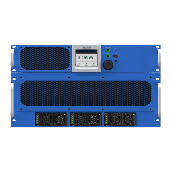
- Page 159 FRONT PANEL DISPLAY (U1) FAN (B1 to B5) (located behind panel, B1 on LHS, B5 on RHS) POWER SUPPLY (U1-U3) VX5 shown for reference (UG132 for VX3-VX4 and UG136 for VX5 -VX6) Figure MD-4: VX3-VX6 Transmitter (front view) VERSION 1.0 2023-08-16 MD-4...
- Page 160 Figure MD-5: NAPI189 Analog Audio PWB VERSION 1.0 2023-08-16 MD-5...
- Page 161 Figure MD-6: NAPI204 Exciter/Controller System Interface PWB VERSION 1.0 2023-08-16 MD-6...
- Page 162 Figure MD-7: NAPI201/01 Power Supply Interface PWB (VX3, VX3.5, VX4) VERSION 1.0 2023-08-16 MD-7...
- Page 163 Figure MD-8: NAPI201 Power Supply Interface PWB (VX5, VX6) VERSION 1.0 2023-08-16 MD-8...
- Page 164 Figure MD-9: NAPI193 Front Panel User Interface PWB VERSION 1.0 2023-08-16 MD-9...
- Page 165 Figure MD-10: NAPA45 Pre-Amp/IPA PWB VERSION 1.0 2023-08-16 MD-10...
- Page 166 Figure MD-11: NAPA40A Power Amplifier PWB VERSION 1.0 2023-08-16 MD-11...
- Page 167 Figure MD-12: NAPF16A Low Pass Filter PWB VERSION 1.0 2023-08-16 MD-12...
- Page 168 Figure MD-13: NAPH16 6-Way Splitter PWB VERSION 1.0 2023-08-16 MD-13...
- Page 169 Figure MD-14: 6-Way Combiner PWB (Nautel Part # PU30B) VERSION 1.0 2023-08-16 MD-14...
-
Page 170: List Of Terms
Low Voltage Power Supply. A module or modules used in the ac-dc power stage that generates LVPS. the low level dc supply voltage for the transmitter. A setting that controls power level, frequency and audio parameters. The VX3 to VX6 allows Preset. you to pre-program multiple presets. - Page 171 VX-LP TROUBLESHOOTING MANUAL LIST OF TERMS PAGE 3.6.2 VERSION 1.0 2023-08-16...
- Page 173 Phone: +1.902.823.3900 or Fax: +1.902.823.3183 Nautel Inc. 201 Target Industrial Circle Bangor, Maine USA 04401 Phone: +1.207.947.8200 Fax: +1.207.947.3693 Customer Service (24-hour support) +1.877.628.8353 (Canada & USA only) +1.902.823.5100 (International) Email: support@nautel.com Web: www.nautel.com © Copyright 2023 NAUTEL. All rights reserved.
Need help?
Do you have a question about the VX3 and is the answer not in the manual?
Questions and answers