Advertisement
Table of Contents
- 1 Table of Contents
- 2 Introduction
- 3 General Layout
- 4 Technical Data
- 5 Dimensions
- 6 System Details
- 7 Site Requirements
- 8 Initial Preparation
- 9 Installation
- 10 Commissioning the Boiler
- 11 Servicing the Boiler
- 12 Changing Components
- 13 Illustrated Wiring Diagram
- 14 Fault Finding
- 15 Short Parts List
- Download this manual
Advertisement
Table of Contents

Related Manuals for Chappee EDENA CLASSIC E 35


Summary of Contents for Chappee EDENA CLASSIC E 35
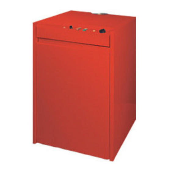
- Page 1 INTALLATION AND SERVICING INSTRUCTIONS E D E N A C L A S S I C E Model : 35 - 43 - 53 - 64 kW Gas Fired Floor Standing Boiler Réf. : CH - 1254 - I - 0 - EN 09/05 Réf.
-
Page 2: Table Of Contents
Contents 1.0 Introduction 2.0 General Layout 3.0 Technical Data 4.0 Dimensions 5.0 System Details 6.0 Site Requirements 7.0 Installation 8.0 Commissioning the boiler 9.0 Servicing the boiler 10.0 Changing Components 11.0 Illustrated Wiring Diagram 12.0 Fault Finding 13.0 Short Parts List Réf. -
Page 3: Introduction
1.0 INTRODUCTION NOTE:This appliance must be installed in accordance with the manufacturer’s instructions and the regulations in force. Read the instructions fully before installing or using the appliance. Boilers are built in accordance with the following European directives: Directive “Low voltage” 73 / 23 / EEC Directive “Electromagnetic 89 / 336 / EEC... -
Page 4: General Layout
2.0 GENERAL LAYOUT Layout Flue Spigot 16. Overheat Thermostat Draught Diverter 17. Boiler Thermostat Cable Clamp 18. Inner Front Panel Flue Safety Thermostat 19. Control Panel Flow Connection 20. Cleaning Brush Return Connection 21. Heat Exchanger Burner 22. Flue Hood Gas Inlet Connection 23. -
Page 5: Technical Data
3.0 TECHNICAL DATA Model CE N° 1312BM3629 1312BM3628 1312BM3626 1312BM3627 Applliance Type B11BS Appliance Categorie gas 2H 3P Heat input 43,07 47,83 58,34 71,83 Heat Ouput 35,0 43,0 52,8 64,5 Gas rate G 20 - 20 mbar 5,06 Burner pressure G 20 - 20 mbar mbar 11,2 ±0,4 11,4 ±0,4... -
Page 6: Dimensions
4.0 DIMENSIONS Model 332,5 427,5 Réf. : CH - 1254 - I - 0 - EN... -
Page 7: System Details
5.0 SYSTEM DETAILS 5.1 Primary Circuit The appliance is suitable for fully pumped systems only. The system can be open vented or sealed. A sealed system must incorporate the following : • Safety Valve • Pressure Gauge • Expansion Vessel •... -
Page 8: Site Requirements
6.0 SITE REQUIREMENTS 6.1 B.S. Codes of Pracitice WARNING : The addition of anything that may interfere with the normal operation of the appliance without the express written permission of BAXI could invalidate the appliance warranty and infringe the GasSafety (Installation and Use) Regulations. - Page 9 6.2 Location 6.5 Flues & Ventilation 1. The boiler must be positioned on a flat and level floor The room or space of installation must be ventilated or base which must be capable of supporting the full to ensure the correct and safe operation of the boiler. operational weight of the boiler.
-
Page 10: Installation
7.0 INSTALLATION Securing Screws Top Panel 7.1 Initial Preparation The gas supply, gas type and pressure must be checked for suitability before connection. Ensure that the floor or base on to which the boiler is to be fitted is clean and free from debris. Magnets Install any pipework that will be behind the boiler, and any appropriate flue components. -
Page 11: Commissioning The Boiler
8.0 COMMISSIONING THE BOILER Thermostat Knod 8.1 Commisioning the Boiler 1. Open the water supply to the boiler. 2. The system must be flushed, (see Section 5.1 of these instructions and the flushing agent manufactu- rer's instructions). 3. Turn the gas supply on and purge the system. Test for gas soundness. -
Page 12: Servicing The Boiler
9.0 SERVICING THE BOILER Securing Screws Top Panel 9.1 Annual Servicing For reasons of safety and economy, it is recommended that the boiler is serviced annually. Servicing must be performed by a competent person. Ensure that the boiler is cool. Magnets Ensure that both the gas and electrical supplies to the boiler are isolated. -
Page 13: Changing Components
10.0 CHANGING COMPONENTS Securing Screws Top Panel IMPORTANT : When changing components ensure thatboth the gas and electrical supplies to the boiler are isolated before any work is started. Undo the two securing screws from the rear of the top panel. - Page 14 10.3 Gas Valve Sealing Washer Undo the disconnecting union on the gas inlet. Remove Gas Cock the screw securing the burner ignition control to the gas valve. Draw the control off the valve. Undo the two nuts securing the valve, injector mani- Disconnecting Securing fold and burner assembly to the boiler.
- Page 15 10.7 Flue Safety Thermostat 1. Undo the nut securing the Flue Safety Thermostat to the draught diverter. Ease the cable clamp from the slot in the draught diverter. 2. Undo the screw retaining the earth wire to the boiler and disconnect the plug on the Flue Safety Thermos- tat cable from the boiler harness.
-
Page 16: Illustrated Wiring Diagram
11.0 ILLUSTRATED WIRING DIAGRAM b 50 Flame Failure w 27 Neon (Red) Power ON Neon Flame Failure (orange) Burner ON Rest Button Neon (green) w 61 b 50 Safety Thermostat b 50 ON / OFF Button Safety Thermostat Neon (Red) b 30 Control Thermostat w 42... -
Page 17: Fault Finding
12.0 FAULT FINDING This page shows the configuration of the plug and socket on the Burner Ignition Control supply. The socket is part of the boiler harness and the plug is on the lead connected to the Burner Ignition Control. Illustrates the layout of the edge connector on the Burner Ignition Control. - Page 18 Is the “Power On” neon Is there 230V at SWL & N Does the On/Off button START illuminated ? on terminal strip? illuminate when pressed in? Electrical fault external to Is there permanent live Is there 230V at L & N of boiler to the boiler? the On/Off button?
- Page 19 Is there a spark at the Does the pump run ? electrode? Is there 230V at PL & PN Is the Boiler Safety on the terminal strip? Overheat neon illuminated? Check pump or pump Unscrew the cover and wiring press the reset button Check boiler internal Check and clean the wiring...
- Page 20 BOILER Does the boiler shut down Does the pilot burner Do the main burners light ? OPERATING when the flow flame light ? CORRECTLY temperature reaches 85°? Ensure control knob is fully Does the spark continue Is there 20mb pressure at clockwise and the for 25 seconds? Gas Valve inlet?
-
Page 21: Short Parts List
13.0 SHORT PARTS LIST Short Parts List Description Manufactuers Part No. Gas Valve Assembly S17074500 Burner S17000837 Main Burner Injector S17003199 Injecteur Washer S17006504 Control Thermostat S133624 Safety Thermostat S17006955 Pilot Burner Assembly S133535 Burner Ignition Control S17000601 Flue Products Safety Thermostat S500540 Pilot Injector S17003216... - Page 22 NOTES Réf. : CH - 1254 - I - 0 - EN...
- Page 23 Réf. : CH - 1254 - I - 0 - EN...
- Page 24 93158 Le Blanc-Mesnil - Cedex Telephone : + 33 (0)1 45 91 56 00 : + 33 (0)1 45 91 59 50 www.chappee.com S A au capital de 43 214 640 € RCS Bobigny B 602 041 675 A.P.E 282 D Réf.
Need help?
Do you have a question about the EDENA CLASSIC E 35 and is the answer not in the manual?
Questions and answers