Küschall K Series Service Manual
Active wheelchair
Hide thumbs
Also See for K Series:
- User manual (60 pages) ,
- Service manual (28 pages) ,
- User manual (29 pages)
Table of Contents
Advertisement
Quick Links
Download this manual
See also:
User Manual
Advertisement
Table of Contents

Subscribe to Our Youtube Channel
Related Manuals for Küschall K Series


Summary of Contents for Küschall K Series
- Page 1 Küschall® K-Series en Active wheelchair Service Manual PROVIDER: Keep this manual. The procedures in this manual MUST be performed by a qualified technician.
- Page 2 © 2019 Invacare Corporation All rights reserved. Republication, duplication or modification in whole or in part is prohibited without prior written permission from Invacare. Trademarks are identified by ™ and ®. All trademarks are owned by or licensed to Invacare Corporation or its subsidiaries unless otherwise noted.
-
Page 3: Table Of Contents
Contents 1 General ......... 4 1.1 Introduction . -
Page 4: General
Küschall® K-Series 1 General 1.1 Introduction This document contains important information about assembly, adjustment and advanced maintenance of the product. To ensure safety when handling the product, read this document and the user manual carefully and follow the safety instructions. Find the user manual on Invacare’s website or contact your Invacare representative. -
Page 5: Safety
Safety 2 Safety 2.1 General Safety Information WARNING! Risk of injury or damage to property – The procedures in this manual must only be performed by a qualified technician. – Use only original options and spare parts. – Do not handle this product or any available optional equipment without first completely reading and understanding these instructions and any additional instructional material such as user manuals, installation manuals or instruction sheets supplied with this product or optional equipment. - Page 6 Küschall® K-Series IMPORTANT! – If possible, continue to use the old identification label; if this is not possible, the new identification label must contain the same information and the old serial number. (Replacement of spare parts with serial numbers). – When components are replaced it is necessary to ensure the traceability of the components replaced. –...
-
Page 7: Product Overview
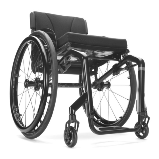
Product Overview 3 Product Overview 3.1 Main parts of the wheelchair A Backrest B Clothes-guard C Seat with cushion D Frame E Footrest F Castor fork with castor wheel G Parking brake H Rear wheel with handrim and quick-release axle 3.2 Dimensions Seat depth (SD) 350 –... -
Page 8: Servicing
Küschall® K-Series 4 Servicing 4.1 Inspection checklist General inspection ☐ ☐ Is the product in good condition and is it complete (product and optional equipment)? ☐ ☐ Is the product free from damage or weaknesses of any kind? ☐ ☐ Does the product operate correctly under nominal load? ☐... -
Page 9: Reconditioning
Reconditioning 5 Reconditioning 5.1 Cleaning IMPORTANT! – The product does not tolerate cleaning in automatic washing plants, with high-pressure cleaning equipment or steam. IMPORTANT! Dirt, sand and seawater can damage the bearings and steel parts can rust if the surface is damaged. –... -
Page 10: Reconditioning Scheme
Küschall® K-Series 5.4 Reconditioning scheme The following items must be reviewed and checked when reconditioning is required: Symptoms Faults Solution Incorrect tyre pressure on one The wheelchair does not Correct tyre pressure, see user manual rear wheel travel in a straight line One or more spokes broken Replace broken spoke(s) Spokes tightened unevenly... -
Page 11: Instructions
Instructions 6 Instructions 1659339-A... -
Page 12: Frame Overview
Küschall® K-Series 6.1 Frame overview The Küschall® K-Series frame is made from aluminum. Frame angles of 75° and 90° are existing. The frames are available in a standard version, a tapered version and a plus 50 mm version. Frame Front seat-to- Seat depth Lower leg length (LLL) with Lower leg length (LLL) with... -
Page 13: Seat
Instructions 6.2 Seat 6.2.1 Seat width (SW) Available seat widths: SW 320 to 500 in 20 mm steps. Changing the seat width is very complicated and requires the replacement of numerous parts. 6.2.2 Seat depth (SD) Available seat depths: SD 350 to 525 in 25 mm steps. Changing the seat depth requires the replacement of the complete seat module including the seat cover and the seat rail and potentially also the seat cushion. - Page 14 Küschall® K-Series Rear seat height based on wheel position and wheel size 24” wheel 25” wheel 26” wheel RSTF [mm] — — — — — — — — — — — — — — — — — — — — —...
-
Page 15: Adjusting The Tipping Point
Instructions 6.2.6 Adjusting the tipping point ■■■ Allen key (4 mm, 5 mm) / Socket spanner (8 mm) 1. Remove the rear wheels, fold the backrest forward and place the wheelchair on its back. 2. Remove the bolts A, B and E. 3. -
Page 16: Installing A Suspension
Küschall® K-Series 6.2.7 Installing a suspension A suspension can be fitted for a rear seat-to-floor height (RSTF) of between 380 mm and 460 mm. The use of a seat module with the welded cross brace is required when installing the suspension. ■■■... -
Page 17: Backrest
Instructions 6.3 Backrest 6.3.1 Tension adjustable backrest The adjustable back is fitted with hook and loop bands and a cover. Apart from the adjustable back there is the light cover, which is produced individually for each backrest height (BH) and seat width (SW). Possible backrest heights (BH) in relation to cover, backrest tube, push handles and bands Standard push handles A / Foldable push handles... -
Page 18: Backrest Height (Bh)
Küschall® K-Series Possible backrest heights (BH) to push handles, telescopic tubes and bands Height-adjustable push handles Without push handles C rear-set D Tele- scopic tube Bands above Top band bended Bands above Top band [mm] stabilizing bar stabilizing bar — —... -
Page 19: Backrest Angle (Ba)
Instructions 6.3.3 Backrest angle (BA) The angle of the backrest can be changed by repositioning the excenter plate in the backrest joint plate. The following angles (measured from the seat) can be set: 74° 78° 82° 86° 90° Adjusting the backrest angle ■■□... -
Page 20: Installing/Adjusting The Release Cord
Küschall® K-Series 6.3.4 Installing/adjusting the release cord — ■■□ WARNING! Risk of injury to the user during use as a result of the backrest folding over unintentionally. If the release cord is too taut, the locking mechanism B can open unintentionally. –... -
Page 21: Replacing The Backrest Tube
Instructions 6.3.5 Replacing the backrest tube ■□□ Allen key (3 mm, 4 mm) / Socket spanner (8 mm, 10 mm) 1. Remove the backrest cover. 2. Slide the backrest bands upwards or downwards to gain access to the screws A. Remove the screws and nuts on both sides. 3. -
Page 22: Replacing The Handle
Küschall® K-Series 6.3.6 Replacing the handle An adhesive (e.g. hair spray) is used in these instructions. When applied to the handle, this substance works as a lubricant and as an adhesive once dry. CAUTION! Risk of accidents due to the handle comes loose –... -
Page 23: Footrests
Instructions 6.4 Footrests The footrest must be selected in accordance with the seat width. Standard footrests and angle-adjustable footrests are available. Furthermore, there is a choice between a high-mounted footrest and a fold-up footrest. Lower leg length (LLL) To change the lower leg length, the footrest can be installed in a higher or lower position, see 6.4.2 Adjusting the footrest height, page 23. -
Page 24: Installing/Replacing The Foot Plate
Küschall® K-Series 6.4.3 Installing/replacing the foot plate ■■□ Allen key (3 mm) / Screw clamps / Drill, drill bit (7 mm) 1. Position and fasten the foot plate A cleanly to the footrest B using screw clamps. 2. Center punch the footrest through the holes on the foot plate. 3. - Page 25 Instructions 1. Remove the high-mounted footrest A by removing bolts B, washers C and clamping parts D. 2. Install the high-mounted footrest by reversing step 1. B = 7 Nm 1659339-A...
-
Page 26: Installing The Flip-Up Footrest
Küschall® K-Series 6.4.6 Installing the flip-up footrest ■□□ Allen key (4 mm) / Socket spanner (8 mm) 1. Slide the footrest tubes A and E into the clamping part 2. Install the foot plate J using bolts K, washers L and nuts M. -
Page 27: Sideparts
Instructions 6.5 Sideparts 6.5.1 Clothes-guard / Mudguard The clothes-guard fitted as standard can be replaced by a mudguard. Clothes-guard and mudguard are available in plastic or in carbon. For the carbon mudguard there is an additional size (XL) for the two smallest rear seat-to-floor heights (RSTF). Plastic clothes-guard sizes according to rear wheel size and position 24”... - Page 28 Küschall® K-Series Plastic removable mudguard sizes according to rear wheel size and position 24” Rear wheel 25” Rear wheel 26” Rear wheel Position Position Position RSTF [mm] — — — — — — — — — — — — — —...
- Page 29 Instructions Replacing the clothes-guard ■■□ Allen key (3 mm, 4 mm) 1. If present, remove the clothes-guard to be replaced by loosening the screw connection C. 2. Install the mounting element A with parts F, E, D on the backrest tube G. 3.
- Page 30 Küschall® K-Series Installing the mudguard ■■□ Allen key (3 mm, 4 mm) / Socket spanner (10 mm) / Phillips screwdriver (2 mm) 1. Remove the clothes-guard and the mounting elements on the backrest and the seat. 2. Install the holder B to the seat module using the screw connections A and plate C and then refit the rear wheel.
-
Page 31: Installing The Tubular Armrest
Instructions 6.5.2 Installing the tubular armrest WARNING! Risk of injuries due to incorrect installation If the tubular armrest option is to be installed, the seat module must be cut off depending on the configuration of the wheelchair. – The tubular armrest must only be installed by Invacare shop assembly. Therefore, contact Invacare customer service. -
Page 32: Castors
Küschall® K-Series 6.6 Castors 6.6.1 Replacing the castor wheel IMPORTANT! The following sub-assembly contains pre-coated screws. – Only use original Invacare spare parts. – If the screws need adjustment, replace by new ones. Only use original Invacare spare parts. Any change in the adjustment of these screws requires a change of screw. ■□□... -
Page 33: Replacing The Castor Fork
Instructions 6.6.2 Replacing the castor fork IMPORTANT! The following sub-assembly contains pre-coated screws. – Only use original Invacare spare parts. – If the screws need adjustment, replace by new ones. ■■□ Socket spanner (10 mm) / Wrench (17 mm) 1. Remove the castor wheel, see 6.6.1 Replacing the castor wheel, page 32. -
Page 34: Adjusting The Removable Axle
Küschall® K-Series 1. Loosen the bolts A on both clamp sets. 2. Rotate the axle tube B to set the correct position. 3. Retighten the bolts on both sides. This setting must be carried out on a horizontal surface. The track of the rear wheels is correct if the distance between the rear wheels is the same at the front and the back (x=y) –... - Page 35 Instructions It is possible to install two axles, if a rear wheel extension with five positions is mounted. Clothes-guard Camber angle SW 320 SW 340 SW 360 SW 380 SW 400 SW 420 SW 440 SW 460 SW 480 SW 500 1.
- Page 36 Küschall® K-Series ■■□ Allen key (5 mm) 1. Remove both rear wheels. 2. Remove the bolts A on both sides and open up the lower part of the axle holder B. 3. Replace the axle C with a new one with the desired wheel camber.
-
Page 37: Repairing Or Changing An Inner Tube
Instructions 6.7.5 Repairing or changing an inner tube ■■□ Tyre lever 1. Remove the rear wheel and release any air from the inner tube. 2. Lift one tyre wall away from the rim using a bicycle tyre lever. Do not use sharp objects such as a screwdriver which could damage the inner tube. -
Page 38: Parking Brakes
Küschall® K-Series 6.8 Parking brakes 6.8.1 Installing the parking brake ■■□ Allen key (5 mm) 1. Position the brake holder B around the front frame tube C. 2. Place the brake D in the brake holder. 3. Screw the bolt A with washer into the brake assembly but do not tighten. -
Page 39: Options
Instructions 6.9 Options 6.9.1 Installing/adjusting the antitipper There are two different sizes of antitipper for both the left and the right sides. ■■□ Allen key (3 mm, 5 mm) / Socket spanner (8 mm, 10 mm) Without rear wheel extension 1. -
Page 40: Installing/Adjusting The Transit Wheels
Küschall® K-Series Installing/adjusting the active antitipper ■■■ Allen key (3 mm, 5 mm) / Socket spanner (8 mm) / Drill & drill bit (6 mm) 1. Fit the holder A to the axle tube. Here, only lightly tighten the bolts B. 2. -
Page 41: Installing The Posture Belt
Instructions 6.9.3 Installing the posture belt ■■□ Allen key (5 mm) / Socket spanner (10) 1. Remove cap nut A and washer C. 2. Attach the steel strap D to the backrest joint screw B using the supplied, new cap nut and washer. A = 7 Nm WARNING! Risk of injury due to incorrect installation... - Page 42 Küschall® K-Series Front side Rear side 1659339-A...
- Page 43 Notes...
- Page 44 Invacare distributors Asia: Australia: Belgium & Luxemburg: Danmark: Invacare Asia Ltd. Invacare Australia Pty. Ltd. Invacare nv Invacare A/S 1 Lenton Place, North Rocks NSW 2151 1 Lenton Place, North Rocks NSW 2151 Autobaan 22 Sdr. Ringvej 37 Australia Australia B-8210 Loppem DK-2605 Brøndby Phone: (61) (02) 8839 5333...
Need help?
Do you have a question about the K Series and is the answer not in the manual?
Questions and answers