Kuschall K-Series Service Manual
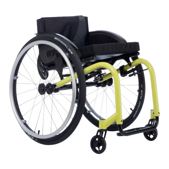
Kuschall k-series wheelchair
Hide thumbs
Also See for K-Series:
- User manual (60 pages) ,
- Service manual (44 pages) ,
- Service manual (28 pages)
Table of Contents
Advertisement
Advertisement
Table of Contents

Related Manuals for Kuschall K-Series


Summary of Contents for Kuschall K-Series
- Page 1 Service manual...
-
Page 3: Table Of Contents
Service manual Table of contents General ......................... 4 Introduction Spare parts and adaptations Tightening Allen screws Torque Checks Identifying and alleviating malfunctions Frame ..........................6 Seat ..........................7 Seat width (SB) Seat depth (ST) Front seat height (SHv) Rear seat height (SHh) Seat angle (SW) Tipping point adjustment Suspension... -
Page 4: General
Service manual General Introduction This service manual is part of the instructions and contains the technical information for servicing, configuring and repairing a Küschall® wheelchair. To guarantee the required safety and reliability, all wheelchairs must be comprehensively checked once a year. In part, assembly and adjustment require extensive experience. -
Page 5: Torque
Service manual Torque All screw connections must be tightened with the torques specified in the following instructions. Checks Visual check Check the entire frame for cracks, especially the areas around joints and welded seams. Checking the screw connections Check all screw connections with the torques specified in the instructions. -
Page 6: Frame
Frame Frame The K-Series frame is available in aluminium, titanium and carbon. Aluminium and titanium frames come with frame angles of 75° and 90°; carbon frames come with a frame angle of 75°. Furthermore, the 75° and the 90° aluminium frames come with adduction and in a short, respective +5 version. -
Page 7: Seat
Service manual Seat Seat Seat width (SB) Available seat widths: SB 340 to 480 in 20 mm steps. Changing the seat width is very complicated. The seat module, the backrest, the real wheel axles and the footrest have to be replaced. Seat depth (ST) Available seat depths: ST 375 to 525 in 25 mm steps. - Page 8 Service manual Seat Possible front and rear wheel combinations Rear wheel Frame 75° short 24‘‘ 75° / 75 / 90° °+5 short 90° / 90° 75° short 25‘‘ 75° / 75° / 90° short 90° / 90° 75° / 75° 26‘‘...
-
Page 9: Rear Seat Height (Shh)
Service manual Seat Rear seat height (SHh) The seat braces can be repositioned to adjust the rear seat height. The seat braces are available in three different sizes, covering seat heights of between 380 and 490 mm. Generally, we recommend fixing the seat braces to the lower hole on the frame. -
Page 10: Tipping Point Adjustment
Service manual Seat Tipping point adjustment The tipping point of the wheelchair can be adjusted by changing the hori- zontal position of the seat module. à 4, 5 Difficulty: Tools: ˜˜˜ Remove the rear wheels, fold the backrest forward and place the ... -
Page 11: Backrest
Service manual Backrest Backrest The adjustable back is fitted with velcro bands and a cover. Apart from the adjustable back there is the light cover, which is produced individually for each backrest height (RH) and seat width (SB). Backrest height (RH) to cover, backrest tube, pushhandles and bands ... -
Page 12: Backrest Height (Rh)
Service manual Backrest Backrest height (RH) The height of the backrest can be adjusted by moving the backrest tube. Adjusting the backrest height Readjusting the push handle/telescopic tube à 3 Difficulty: Tools: ˜™™ Remove the backrest padding. Remove the screw connection and adjust the desired height of the ... -
Page 13: Replacing The Backrest Tube
Service manual Backrest Replacing the backrest tube à 3,4 8, 10 Difficulty: Tools: ˜™™ Remove the backrest padding. Slide the backrest bands upwards or downwards to gain access to the screws . Remove the screws and nuts on both sides. Remove the push handles or the telescopic tubes and remove the ... -
Page 14: Replacing The Handle
Service manual Backrest Replacing the handle An adhesive (e.g. hair spray) is used in these instructions. When applied to the handle, this substance works as a lubricant and as an adhesive once dry. After drying, the adhesive used must be able to resist a pull-off force of 750 N. -
Page 15: Backrest Angle (Rw)
Service manual Backrest Backrest angle (RW) The angle of the backrest can be changed by repositioning the excentre plate in the backrest joint plate. The following angles (measured from the seat) can be set: 74° 78° 82° 86° 90° Adjusting the backrest angle Difficulty: Tools: Ã... -
Page 16: Footrests
Service manual Footrests Footrests The footrest must be selected in accordance with the seat width. A stan- dard footrest and an angle-adjustable footrest are available. Furthermore, there is a choice between a high-mounted footrest and a fold-up footrest. Lower leg length (UL) To change the lower leg length, the footrest can be fixed at a higher or lower position. -
Page 17: Fitting And Adjusting High-Mounted Footrest
Service manual Footrests Fitting and adjusting high-mounted footrest à 4, 5 8, 10 Difficulty: Tools: ˜™™ Fit the frame bar for the high-mounted footrest to the front frame on both sides using the screw connections . Fix the clamp set to both sides of the frame using the screw ... -
Page 18: Side Parts
Service manual Side parts Side parts Armrest The clothes-guard fitted as standard can be augmented with an armrest. Fitting and adjusting an armrest Difficulty: Tools: à 3, 4, 5 8, 10 ˜˜™ Fold the backrest forwards. Remove the backrest spigots and replace them with the armrest ... -
Page 19: Clothes-Guard/Mudguard
Service manual Side parts Clothes-guard/mudguard The clothes-guard fitted as standard can be replaced by a mudguard. Clothes-guard and mudguard are available in plastic or in carbon. For the carbon mudguard there is an addi- tional size (XL) for the two smallest rear seat hights (SHh). Clothes-guard size Wheel size 24‘‘... - Page 20 Service manual Side parts Replacing the clothes-guard The mounting element on the backrest must already be fitted. Difficulty: Tools: à 3, 4 ˜˜™ If present, remove the clothes-guard to be replaced by loosening the screw connection . Check the correct position of the clothes-guard with fitted rear ...
-
Page 21: Front Wheels
Service manual Front wheels Front wheels Replacing a front wheel à 2x3 Difficulty: Tools: ˜™™ Remove the screw with disk on one side. Remove the wheel axle . Remove the front wheel . Place the sleeves between the new front wheel and the fork. ... -
Page 22: Rear Wheels
Service manual Rear wheels Rear wheels Ensuring the rear wheels are parallel à 5 Difficulty: Tools: ˜˜™ Loosen the screws on both clamp sets. Rotate the axle tube to set the correct position. Tighten the screw on both sides. ... -
Page 23: Changing The Wheel Chamber / Fitting And Adjusting An Axle
Service manual Rear wheels Changing the wheel chamber / Fitting and adjusting an axle Standard axle Difficulty: Tools: à 5 ˜˜™ A new axle must be used to change the wheel chamber. Remove the screws on both sides and open up the lower part of the ... -
Page 24: Brakes
Service manual Brakes Brakes Fitting / adjusting the parking brake à 5 Difficulty: Tools: ˜˜™ Following each positioning, the rear wheel parking brakes (e.g. when changing the wheel chamber) must be readjusted. The parking brake function is only guaranteed if the tire has the corresponding air pressure. -
Page 25: Options & Accessories
Service manual Options & accessories Options & accessories Antitipper There are two different sizes of antitipper for both the left and the right sides. Fit antitipper without rear wheel extension à 3, 5 Difficulty: Tools: ˜˜™ Loosen the screw and the screw connection and remove the ... -
Page 26: Active Antitipper
Service manual Options & accessories Active antitipper Fitting and adjusting an active antitipper Difficulty: Tools: à 3, 5 ˜˜˜ Fit the holder to the axle tube. Here, only lightly tighten the screws . Remove the QuickPin , slide the active antitipper over the holder and ... -
Page 27: Fitting The Pelvic Belt
Service manual Options & accessories Fitting the pelvic belt 10 mm Difficulty: Tools: ˜™™ 1. Remove cap nut and washer . 2. Attach the steel strap to the backrest joint screw using the sup- plied, new cap nut and washer . Ensure that the webbing of the pelvic belt is not twisted during assembly and the locking mechanism shows towards the front. - Page 28 Benkenstrasse 260 CH-4108 Witterswil kueschall@invacare.com www.kueschall.com Service manual K-Series ENGLISH | 2012-07 küschall® distributors Belgium & Luxemburg: Invacare nv • Autobaan 22 • B-8210 Loppem Tel: (32) (0)50 83 10 10 • Fax: (32) (0)50 83 10 11 • belgium@invacare.com Danmark: Invacare A/S •...
Need help?
Do you have a question about the K-Series and is the answer not in the manual?
Questions and answers