Küschall KSL Service Manual
Active wheelchair
Hide thumbs
Also See for KSL:
- User manual (48 pages) ,
- Service manual (22 pages) ,
- Service manual (20 pages)

Related Manuals for Küschall KSL


Summary of Contents for Küschall KSL
- Page 1 The KSL en Active wheelchair Service Manual PROVIDER: Keep this manual. The procedures in this manual MUST be performed by a qualified technician.
- Page 2 © 2020 Invacare Corporation All rights reserved. Republication, duplication or modification in whole or in part is prohibited without prior written permission from Invacare. Trademarks are identified by ™ and ®. All trademarks are owned by or licensed to Invacare Corporation or its subsidiaries unless otherwise noted.
-
Page 3: Table Of Contents
Contents 1 General ......... 4 1.1 Introduction . -
Page 4: General
The KSL 1 General 1.1 Introduction This document contains important information about assembly, adjustment and advanced maintenance of the product. To ensure safety when handling the product, read this document and the user manual carefully and follow the safety instructions. -
Page 5: Safety
Safety 2 Safety 2.1 General Safety Information WARNING! Risk of injury or damage to property – The procedures in this manual must only be performed by a qualified technician. – Use only original options and spare parts. – Do not handle this product or any available optional equipment without first completely reading and understanding these instructions and any additional instructional material such as user manuals, installation manuals or instruction sheets supplied with this product or optional equipment. - Page 6 The KSL IMPORTANT! – If possible, continue to use the old identification label; if this is not possible, the new identification label must contain the same information and the old serial number. (Replacement of spare parts with serial numbers). – When components are replaced it is necessary to ensure the traceability of the components replaced.
-
Page 7: Product Overview
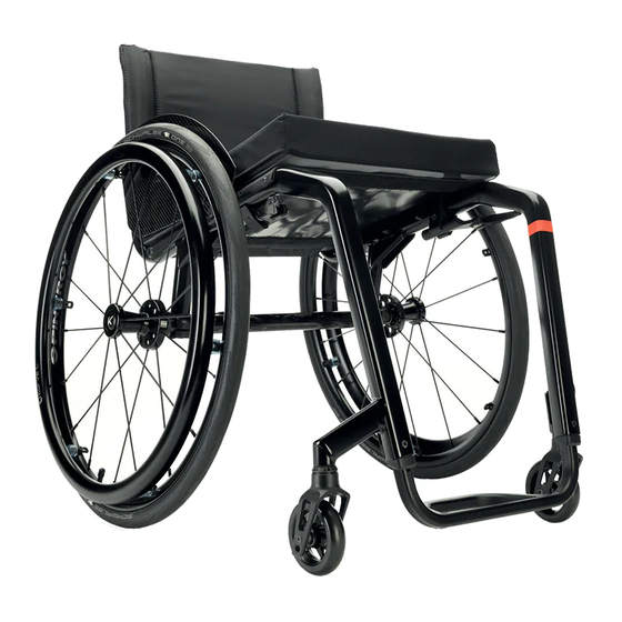
Product Overview 3 Product Overview 3.1 Main parts of the wheelchair A Backrest B Clothes-guard C Seat with cushion D Frame E Footrest F Castor fork with castor wheel G Parking brake H Rear wheel with handrim and quick-release axle 3.2 Dimensions 385 –... -
Page 8: Servicing
The KSL 4 Servicing 4.1 Inspection checklist General inspection ☐ ☐ Is the product in good condition and is it complete (product and optional equipment)? ☐ ☐ Is the product free from damage or weaknesses of any kind? ☐ ☐... -
Page 9: Reconditioning
Reconditioning 5 Reconditioning 5.1 Cleaning IMPORTANT! – The product does not tolerate cleaning in automatic washing plants, with high-pressure cleaning equipment or steam. IMPORTANT! Dirt, sand and seawater can damage the bearings and steel parts can rust if the surface is damaged. –... -
Page 10: Reconditioning Scheme
The KSL 5.4 Reconditioning scheme The following items must be reviewed and checked when reconditioning is required: Symptoms Faults Solution Incorrect tyre pressure on one The wheelchair does not Correct tyre pressure, see user manual rear wheel travel in a straight line... -
Page 11: Instructions
Instructions 6 Instructions 6.1 Frame overview Adjusting the frame The seat width, seat depth, lower leg length and tipping point are determined by the design of the frame and cannot be changed retrospectively. A modification of the tip behaviour can only be achieved by ordering a new, one-off backrest. The seat depth can be adjusted by changing the hole position. -
Page 12: Seat
The KSL 6.2 Seat 6.2.1 Adjusting the seat height (SH) The seat height can only be adjusted by fitting a larger or smaller rear wheel and at the same time using a larger or smaller castor fork and castor. Possible Front Seat-to-Floor Heights (FSTF) [mm]: 450 – 530. As the seat angle is dictated by the design of the frame, the Rear Seat-to-Floor Height (RSTF) also changes by 10 mm. - Page 13 Instructions 1. Remove mudguard or clothes guard by removing bolts A with washers, spacers and nuts on both sides. 2. Remove bolts B, C and D with washers on both sides of the seat cover. 3. Remove seat cover E and replace with new one. Owing to the tension inherent in the design of the frame, it may not be possible to fit the seat cover.
-
Page 14: Backrest
The KSL 6.3 Backrest 6.3.1 Adjusting the Backrest Height (BH) Possible backrest heights (BH): BH [mm] ■■■ Allen key (3 mm) 1. Remove the backrest cover. 2. Remove the bolt A and adjust the required height of the push handle or the telescopic tube by bringing the threaded insert B to the appropriate position. -
Page 15: Replacing The Foldable, Angle-Adjustable
Instructions The upper backrest bands can be taken straight off, the backrest must be removed in order to access the lower ones. 1. Remove the backrest cover. 2. Remove the mudguard or clothes guard. 3. Push the backrest band down in order to access the bolts A. 4. - Page 16 The KSL 1. Remove the mudguard or clothes-guard on both sides. 2. Remove the seat cover. 3. Remove old backrest, see 6.3.3 Replacing the Backrest / Backrest Bands, page 14. 4. On both sides, drill a new hole A in the frame with a ø...
-
Page 17: Replacing The Handle
Instructions 6.3.5 Replacing the handle An adhesive (e.g. hair spray) is used in these instructions. When applied to the handle, this substance works as a lubricant and as an adhesive once dry. CAUTION! Risk of accidents due to the handle comes loose –... -
Page 18: Footrests
The KSL 6.4 Footrests The footrest must be selected in accordance with the seat width. Standard footrests and angle-adjustable footrests are available. Furthermore, there is a choice between a high-mounted footrest and a fold-up footrest. Lower leg length (LLL) To change the lower leg length, the footrest can be installed in a higher or lower position, see 6.4.2 Adjusting the footrest height, page 18. -
Page 19: Installing/Replacing The Foot Plate
Instructions 6.4.3 Installing/replacing the foot plate ■■□ Allen key (3 mm) / Screw clamps / Drill, drill bit (Æ 7 mm) 1. Position and fasten the foot plate A cleanly to the footrest B using screw clamps. 2. Center punch the footrest through the holes on the foot plate. 3. -
Page 20: Sideparts
The KSL 6.5 Sideparts 6.5.1 Replacing the Mudguard Seven different mudguard sizes are available. The mudguards are made from Carbon fibre. ■■□ Allen key (5 mm) / Socket spanner (8 mm) / Drill & Drill bit (Æ 5,2 mm) The mudguard is customised to fit the geometry of the individual wheelchair. - Page 21 Instructions The clothes-guard is customised to fit the geometry of the individual wheelchair. It must therefore only be replaced by another clothes-guard of the same size. 1. Remove screws and spacers B and C, distance pieces D and E, nuts with washers F and the clothes-guards A on both sides.
-
Page 22: Castors
The KSL 6.6 Castors 6.6.1 Replacing the castor wheel IMPORTANT! The following sub-assembly contains pre-coated screws. – Only use original Invacare spare parts. – If the screws need adjustment, replace by new ones. Only use original Invacare spare parts. Any change in the adjustment of these screws requires a change of screw. -
Page 23: Replacing The Castor Fork
Instructions 6.6.2 Replacing the castor fork IMPORTANT! The following sub-assembly contains pre-coated screws. – Only use original Invacare spare parts. – If the screws need adjustment, replace by new ones. ■■□ Socket spanner (10 mm) / Wrench (17 mm) 1. Remove the castor wheel, see 6.6.1 Replacing the castor wheel, page 22. -
Page 24: Adjusting The Removable Axle
The KSL This setting must be carried out on a horizontal surface. The track of the rear wheels is correct if the distance between the rear wheels is the same at the front and the back (x=y) – measured at the height of the centre of the axle. -
Page 25: Replacing A Solid Tire
Instructions 1. Remove the rear wheel and release any air from the inner tube. 2. Lift one tyre wall away from the rim using a bicycle tyre lever. Do not use sharp objects such as a screwdriver which could damage the inner tube. 3. -
Page 26: Parking Brakes
The KSL 6.8 Parking brakes 6.8.1 Installing the parking brake ■■□ Allen key (5 mm) 1. Position the brake holder B around the front frame tube C. 2. Place the brake D in the brake holder. 3. Screw the bolt A with washer into the brake assembly but do not tighten. -
Page 27: Options
Instructions 6.9 Options 6.9.1 Installing/Adjusting the Antitipper There are two different sizes of antitipper for both the left and the right sides. ■■□ Allen key (3 mm, 5 mm) / Socket spanner (8 mm, 10 mm) 1. Remove screws A and the lower part B of the axle holder. -
Page 28: Installing The Posture Belt
The KSL 6.9.2 Installing the posture belt ■■□ Allen key (5 mm) / Socket spanner (10) 1. Remove cap nut A and washer C. 2. Install the steel strap D using screw Band washer E with the supplied, new cap nut and washer. - Page 29 Instructions The frame tube needs to be drilled to install the adapter plate. 1. Position the adapter plate C against the seat, aligning the hole with the first frame hole, and the groove with second frame hole. If necessary, reposition the clamping part of the parking brake.
- Page 30 Notes...
- Page 31 Notes...
- Page 32 Invacare distributors Asia: Australia: Belgium & Luxemburg: Danmark: Invacare Asia Ltd. Invacare Australia Pty. Ltd. Invacare nv Invacare A/S 1 Lenton Place, North Rocks NSW 2151 1 Lenton Place, North Rocks NSW 2151 Autobaan 22 Sdr. Ringvej 37 Australia Australia B-8210 Loppem DK-2605 Brøndby Phone: (61) (02) 8839 5333...
Need help?
Do you have a question about the KSL and is the answer not in the manual?
Questions and answers