
Related Manuals for Exsys EX-44384


Summary of Contents for Exsys EX-44384
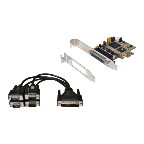
- Page 1 Anleitung EX-44384 RS-232 PCI-e Karte mit 4 x 9 Pin Anschluss RS-232 PCI-e Card with 4 x 9 Pin Connector Vers. 1.0 / 01.08.18 Manual...
-
Page 2: Table Of Contents
Extent of Delivery ··············································································· 10 Layout & Connections ····································································· 11-12 3.1 Layout ····································································································· 11 3.2 Connections ························································································ 11-12 Jumper Settings ············································································ 12-13 Hardware Installation ··········································································· 14 Driver Information ·········································································· 14-16 Technical Information ·········································································· 16 © Copyright 2018 by EXSYS Vertriebs GmbH. All Rights Reserved... -
Page 3: Beschreibung
System (BIOS) und vom Betriebssystem automatisch vorgenommen werden. Die EX-44384 bietet Ihnen die Möglichkeit, +5V und +12V auf Pin 1 und Pin 9 der seriel- len Anschlüsse zur Verfügung zu stellen. Es wird zusätzlich für den Einbau in schmale Computergehäuse ein 8 cm Low Profile Slot-Bügel mitgeliefert. -
Page 4: Aufbau & Anschlüsse
1 DCD 2 RXD 2 RXD 3 TXD 3 TXD 4 DTR 4 DTR 5 GND 5 GND 6 DSR 6 DSR 7 RTS 7 RTS 8 CTS 8 CTS © Copyright 2018 by EXSYS Vertriebs GmbH. All Rights Reserved... - Page 5 = Die Funktion PME ist ausgeschaltet. (Werkseinstellung) = Die Funktion PME ist eingeschaltet. Der PC kann nun durch die Seriellen Ports der EX-44384 aktiviert werden. Dieser sollte aber bei Standard Anwendungen nicht verstellt werden. © Copyright 2018 by EXSYS Vertriebs GmbH. All Rights Reserved...
-
Page 6: Jumper Einstellung
4. Jumper Einstellungen S1~S4_PWR: S1~S4_PWR Jumper Einstellung Kein Power auf Pin1 oder Pin9 Pin1= DCD Pin9= RI (Werkseinstellung) +5V auf Pin1 +12V auf Pin1 +5V auf Pin9 +12V auf Pin9 © Copyright 2018 by EXSYS Vertriebs GmbH. All Rights Reserved... -
Page 7: Hardware Installation
Ordner Ihres Betriebssystems aus und installieren Sie die Treiber (siehe Abbil- dung). Folgen Sie den Installationsanweisungen und schließen Sie die Installation ab. Wichtig! Starten Sie Ihren PC nach der Installation neu. © Copyright 2018 by EXSYS Vertriebs GmbH. All Rights Reserved... - Page 8 ÜBERPRÜFEN DER INSTALLIERTEN TREIBER Öffnen Sie den >Geräte-Manager<. Jetzt müssten Sie unter „Anschlüsse (COM & LPT)“ und unter „Multifunktionsadapter“ folgende Einträge sehen: Sind diese oder ähnliche Einträge vorhanden, ist die Karte richtig installiert. © Copyright 2018 by EXSYS Vertriebs GmbH. All Rights Reserved...
-
Page 9: Technische Daten
0°C bis 55° Celsius Lagertemperatur: -40°C bis 75° Celsius Rel. Luftfeuchtigkeit: 5% bis 95% Stromversorgung: 5V oder 12V vom PC-Netzteil oder 12V vom Mainboard Abmessung: 89,00 x 66,00 mm Gewicht: 800g © Copyright 2018 by EXSYS Vertriebs GmbH. All Rights Reserved... -
Page 10: Description
IRQ settings manually, they will be obtained automatically by the system (BIOS) and operating system. The EX-44384 allows you to provide + 5V and + 12V on pin 1 and pin 9 of the serial ports. There is additionally a 8 cm low profile slot bracket for installation in small computer housing. -
Page 11: Layout & Connections
1 DCD 2 RXD 2 RXD 3 TXD 3 TXD 4 DTR 4 DTR 5 GND 5 GND 6 DSR 6 DSR 7 RTS 7 RTS 8 CTS 8 CTS © Copyright 2018 by EXSYS Vertriebs GmbH. All Rights Reserved... -
Page 12: Jumper Settings
= The function PME is disable. (Factory Setting) = The function PME is enable. Now the card can be activate the computer through the serial ports. But this should not be adjusted for standard applications. © Copyright 2018 by EXSYS Vertriebs GmbH. All Rights Reserved... - Page 13 4. Jumper Settings S1~S4_PWR: S1~S4_PWR Jumper Setting No Power Supplied on Pin1 or Pin9 Pin1= DCD Pin9= RI (Factory Setting) +5V to Pin1 +12V to Pin1 +5V to Pin9 +12V to Pin9 © Copyright 2018 by EXSYS Vertriebs GmbH. All Rights Reserved...
-
Page 14: Hardware Installation
DRIVERS/PCI(PCIe Bridge)“. Please select the folder with your operating system and install the driver (see Picture). Follow the hardware assistant and finish the installation. Important! Restart your PC in any case after installing the drivers. © Copyright 2018 by EXSYS Vertriebs GmbH. All Rights Reserved... - Page 15 Open the >Device manager<. Now you should see at „Ports (COM & LPT)“ and at „Multifunction Adapter“ the following new entry's: If you see this or a similar information the device is installed correctly. © Copyright 2018 by EXSYS Vertriebs GmbH. All Rights Reserved...
-
Page 16: Technical Information
-40°C to 75°C (-40°F to 167°F) Rel. Humidity: 5% to 95% Power: 5V or 12V from PC Power Supply or 12V from Mainboard Size: 89,00 x 66,00 mm Weight: 800g © Copyright 2018 by EXSYS Vertriebs GmbH. All Rights Reserved...
Need help?
Do you have a question about the EX-44384 and is the answer not in the manual?
Questions and answers