Table of Contents
Advertisement
Quick Links
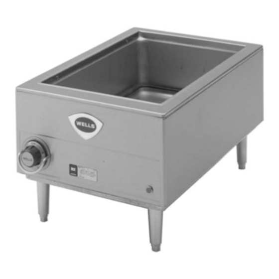
Model HW-SMP
Model HW10
This manual is considered to be part of the appliance and is to be given to the OWNER or
MANAGER of the restaurant, or to the person responsible for TRAINING OPERATORS of
this appliance. Additional manuals are available from your WELLS DEALER.
THIS MANUAL MUST BE READ AND UNDERSTOOD BY ALL PERSONS USING OR
INSTALLING THIS APPLIANCE. Contact your WELLS DEALER if you have any
questions concerning installation, operation or maintenance of this equipment.
Rev. F
2M-305146
265 Hobson Street, Smithville, TN 37166
IMPORTANT: DO NOT DISCARD THIS MANUAL
WELLS MANUFACTURING
telephone: 314-678-6314
fax: 314-781-2714
www.wells-mfg.com
OWNERS MANUAL
WELLS
COUNTERTOP
HW-Series
COOK 'N HOLD
WARMERS
with
THERMOSTAT
CONTROL
MODELS
HW10
HW-SMP
Includes
INSTALLATION
USE & CARE
EXPLODED VIEW
PARTS LIST
WIRING DIAGRAM
005
03/18
Advertisement
Table of Contents

Related Manuals for Wells HW Series


Summary of Contents for Wells HW Series
- Page 1 Additional manuals are available from your WELLS DEALER. THIS MANUAL MUST BE READ AND UNDERSTOOD BY ALL PERSONS USING OR INSTALLING THIS APPLIANCE. Contact your WELLS DEALER if you have any questions concerning installation, operation or maintenance of this equipment.
- Page 2 Wells’ discretion have the parts replaced or codes, including incorrect gas or electrical connection. Wells is not liable repaired by Wells or a Wells-authorized service agency.
-
Page 3: Table Of Contents
PARTS & SERVICE CUSTOMER SERVICE DATA INTRODUCTION Thank You for purchasing this Wells Manufacturing appliance. Proper installation, professional operation and consistent maintenance of this appliance will ensure that it gives you the very best performance and a long, economical service life. -
Page 4: Features & Operating Controls
TEMPERATURE CONTROL KNOB. The knob has a numeric scale, where higher numbers correspond to higher temperature. WELLS 3. On warmers equipped with an INDICATOR LIGHT, the light will glow when the thermostat is calling for heat (i.e. the element is energized). -
Page 5: Precautions & General Information
Damage Do not operate this appliance if the control panel is damaged. Call to the appliance may result if your Authorized Wells Service Agent for service. these instructions are not followed. The technical content of this manual, including any wiring diagrams, schematics, parts breakdown illustrations and/or adjustment procedures, is intended for use by qualified technical personnel. -
Page 6: Installation
INSTALLATION NOTE: DO NOT discard UNPACKING & INSPECTION the carton or other packing Carefully remove the appliance from the carton. Remove all materials until you have protective plastic film, packing materials and accessories from the inspected the appliance for Appliance before connecting electrical power or otherwise performing hidden damage and tested it any installation procedure. -
Page 7: Operation
OPERATION WET OPERATION ONLY CAUTION: HOT SURFACE 1. Carefully read the description of the warmer operation on the specification sheet. Exposed surfaces can be hot to the touch and may cause 2. The warmer is to be used for WET operation ONLY. Add burns. -
Page 8: Cleaning Instructions
Inspect warmer tank for damage. Damage to the outer body may allow grease and water to leak into insulation and heating element, causing a potential fire and/or electric shock hazard. Contact your Authorized Wells Service Agency to inspect warmer if water or grease contamination is suspected. - Page 9 CLEANING INSTRUCTIONS (continued) WEEKLY CLEANING INSTRUCTIONS CAUTION: CHEMICAL BURN PREPARATIONS: Remove any insets, pans and/or adapter tops. HAZARD Drain or remove water from well if used for wet operation. Deilimng chemicals may be caustic. Wear appropriate Weekly, or whenever lime or scale is seen personal protective equipment.
-
Page 10: Troubleshooting Suggestions
Unit not plugged in power receptacle Set control to desired Temperature control not set temperature Warmer will not heat Contact you Authorized Wells Internal damage Service Agency for repairs Pan leaking or other internal Contact your Authorized Wells damage Service Agency for repairs... -
Page 11: Maintenance Instructions
Never use metal implements, wire brushes, abrasive scratch pads or steel wool to clean stainless steel. Warmer pans, insets and other vessels are subject to a harsher environment. Wells Manufac- turing uses an very high quality stainless steel (#304DDQ) for our food warmer pans. Even the... - Page 12 EXPLODED VIEW: HW10 MODEL HW10 Model:HW-10 COUNTERTOP COOK N’ HOLD WARMERS PL005 IL1774 Rev. B 6/23/10...
- Page 13 PARTS LIST: HW10 HW10 COUNTERTOP WARMER Fig No Part No Description Application THERMO HW10 KIT, (INCLUDES CLAMP WS-50290 & SPACER) 2N-35693UL ELEM 120V 1650W HW-10 120V 2N-35967UL ELEM 240V 1650W HW-10 208/230/240V D8-35699 TOP & PAN ASSY HW-10 D8-Z12569 SHELL WRAP, HW10 2E-35539 CORD SET 120V 15A 16GA 4FT 120V...
- Page 14 EXPLODED VIEW: HW-SMP MODEL HW-SMP Insulation Model: HW-SMP COUNTERTOP WARMER PL005 IL1775 Rev. A 5/13/09...
- Page 15 PARTS LIST: HW-SMP HW-SMP 12" X 20" RECTANGULAR WARMER Fig No Part No Description Application D8-30291 CLAMP BULB THERMO HD121 2B-37946 RING THERMO SPACER .310X 2E-35539 CORD SET 120V 15A 16GA 4FT 120V 2E-35540 CORD SET 6-15P 16/3W 4FT 208/240V D8-Z18471 CLAMP ASSY ELEM HW/SMP 2T-40509...
-
Page 16: Wiring Diagram
WIRING DIAGRAM... - Page 17 WIRING DIAGRAM...
-
Page 18: Parts & Service
PARTS & SERVICE Always use an inset. DESCRIPTION PART NO. DO NOT place food directly INSETS into the warmer pan. 2½ QT. ROUND INSET w/ lid WS-20773 4 QT. ROUND INSET w/ lid WS-20774 7 QT. ROUND INSET w/ lid WS-20587 11 QT. - Page 19 For factory authorized service, LEGS or to order factory authorized LEGS, 1” Plastic Adjustable, 4 Needed 2A-41946 replacement parts, contact your Wells authorized service LEGS, 2” Plastic Adjustable, 4 Needed 2A-41946 agency, or call: LEGS, 4” Plastic Adjustable, 4 Needed 2A-30586 Wells Manufacturing LEGS, 4”...
- Page 20 WELLS MANUFACTURING 265 Hobson Street, Smithville, Tennessee 37166 telephone: 314-678-6314 fax: 314-781-2714 www.wells-mfg.com...
Need help?
Do you have a question about the HW Series and is the answer not in the manual?
Questions and answers