Table of Contents
Advertisement
Quick Links
Power Tools Service Manual
PRODUCT NAME
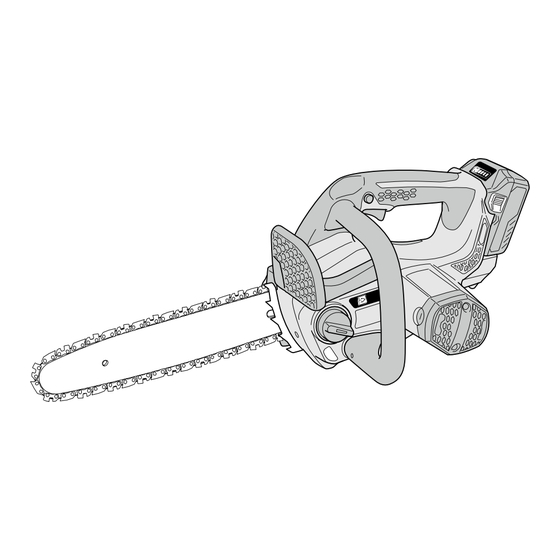
36 V Cordless Chain Saw
CS 3630DA
Model
CONTENTS
REPAIR GUIDE ----------------------------------------------------------------------------------------------------------------- 1
1. Precautions on disassembly and reassembly ------------------------------------------------------------- 1
• Disassembly ----------------------------------------------------------------------------------------------------- 1
• Reassembly ------------------------------------------------------------------------------------------------------ 3
• Lubrication points and type of lubricant ------------------------------------------------------------------- 8
• Tightening torque ----------------------------------------------------------------------------------------------- 8
• Checking after reassembly ----------------------------------------------------------------------------------- 8
• Circuit diagram -------------------------------------------------------------------------------------------------- 9
2. Precautions on disassembly and reassembly of the charger ----------------------------------------- 9
STANDARD REPAIR TIME (UNIT) SCHEDULES---------------------------------------------------------------------10
CONFIDENTIAL
Sep. 2018
Overseas Sales Management Dept.
C
Page
Advertisement
Table of Contents

Related Manuals for HIKOKI CS 3630DA


Summary of Contents for HIKOKI CS 3630DA
-
Page 1: Table Of Contents
Power Tools Service Manual CONFIDENTIAL Sep. 2018 PRODUCT NAME 36 V Cordless Chain Saw CS 3630DA Model CONTENTS Page REPAIR GUIDE ----------------------------------------------------------------------------------------------------------------- 1 1. Precautions on disassembly and reassembly ------------------------------------------------------------- 1 • Disassembly ----------------------------------------------------------------------------------------------------- 1 • Reassembly ------------------------------------------------------------------------------------------------------ 3 • Lubrication points and type of lubricant ------------------------------------------------------------------- 8 •... -
Page 2: Repair Guide
1. Precautions on disassembly and reassembly [Bold] numbers in the description below correspond to the item numbers in the parts list and exploded assembly diagram for the Model CS 3630DA. Disassembly NOTE: Remove all residual chain oil from the oil tank before disassembling the chain saw. If the tank cap is tightened too hard and it is difficult to loosen, insert a flat-blade screwdriver into the groove and rotate it to facilitate removal. - Page 3 5. Removing the inner cover (1) Peel off the tape securing the Urethane Tube 95L [76] to the Oil Tank [77] and remove the Urethane Tube 95L [76] from the Oil Tank [77]. (2) Remove the Tapping Screw D4 x 20 [30] securing the Oil Pump [54] in place. Then remove the Oil Pump [54].
-
Page 4: Reassembly
Reassembly Conduct reassembly by reversing the disassembly procedure, but note the following. 1. Mounting the brush holders (1) Pass the internal wires of the Brush Holders [83] and [89] through the holes on the rear edge of the housing as shown in Fig. 1 paying attention to the polarity of the internal wires. (2) Stick two Sponges (A) [82] to the specified locations as shown in Fig. - Page 5 2. Mounting the magnet (1) Pass the internal wires of the Brush Holders [83] and [89] between the Magnet [51] and the Housing. Handle Cover Set [37]. Ensure that they are not pinched (Fig. 3). (2) Attach the Magnet [51] so that its concave portion correctly meshes with the protrusion on the Housing. Handle Cover Set [37] (Fig.
- Page 6 3. Mounting the front handle (1) Secure the Front Handle [90] to the Housing. Handle Cover Set [37] with four Tapping Screws D4 x 20 [65]. 4. Mounting the oil pump (1) Check that the needle pin D2.5 (included in the Inner Cover [55]) is mounted correctly. (2) Check that the pump gear of the Oil Pump [54] can be rotated lightly at reassembly.
- Page 7 5. Wire connection of the power supply unit (1) Be sure to perform wire connection in accordance with the connecting diagram. Pay attention to colors of the internal wires and the terminals to be soldered. (2) When connecting the internal wires to the two Switches [57], insert the cores of the internal wires into the terminal holes as far as they will go and then secure them with screws.
- Page 8 6. Mounting the spindle and gear (1) Mount the Gear [47] to the Spindle [44] in accordance with the dimensions shown in Fig. 10. (2) Mount the above assembly of the Gear [47] and the Spindle [44] to the Inner Cover [55] being careful not to damage the tooth flank of the pump gear in the Oil Pump [54].
-
Page 9: Lubrication Points And Type Of Lubricant
Lubrication points and type of lubricant Shell Alvania Grease RL3 • Pinion of the Armature and Pinion Set [56]: 2 g • Tooth flank of the Gear [47]: 5 g • Sliding portions of the Brake Link [7], Brake Link Holder [4] and Brake Support Plate [2]: 0.5 g •... -
Page 10: Circuit Diagram
Circuit diagram Fig. 12 • Circuit diagram Controller terminal set LED holder ass’y Battery terminal Ferrite core Switch Switch Ferrite core 2. Precautions on disassembly and reassembly of the charger Refer to the Service Manual for precautions on disassembly and reassembly of the charger Model UC 36YRSL. -
Page 11: Standard Repair Time (Unit) Schedules
STANDARD REPAIR TIME (UNIT) SCHEDULES Repair Model time 60 min. Work Flow CS 3630DA General assembly Brake Link Inner Cover Cover Clutch Brake Support Housing Plate Spindle Brake Lever Ball Bearing Spring 6001VV Brake Link Gear Holder Worm Brake Band... - Page 12 LIST NO. K866 CORDLESS CHAIN SAW 2017 · 12 · 13 Model CS 3630DA (E1)
- Page 13 PARTS CS 3630DA ITEM DESCRIPTION REMARKS CODE NO. CODE NO. USED 335134 BRAKE LINK COVER 6696782 BRAKE SUPPORT PLATE 6696783 BRAKE LEVER SPRING 335135 BRAKE LINK HOLDER 6699013 BRAKE BAND 6685391 NEEDLE ROLLER D3 6685388 BRAKE LINK 6685389 BRAKE SPRING...
- Page 14 PARTS CS 3630DA ITEM DESCRIPTION REMARKS CODE NO. USED 323156 MAGNET 335148 URETHANE TUBE 130L 335147 NOZZLE 6696887 OIL PUMP 335136 INNER COVER 360948 ARMATURE AND PINION SET 335124 SWITCH 335687 INTERNAL WIRE (RED) L240 335694 INTERNAL WIRE (RED) L490 959141 CONNECTOR 50092 (10 PCS.)
- Page 15 STANDARD ACCESSORIES CS 3630DA ITEM DESCRIPTION REMARKS CODE NO. USED 6699116 CHAIN COVER OIL FEEDER (50CC) SUPPLIED WITH ITEM NO.601 CHARGER (MODEL UC 18YSL3) 944458 HEX. BAR WRENCH 4MM 329897 BATTERY COVER OPTIONAL ACCESSORIES ITEM DESCRIPTION REMARKS CODE NO. USED...
Need help?
Do you have a question about the CS 3630DA and is the answer not in the manual?
Questions and answers