Advertisement
Quick Links
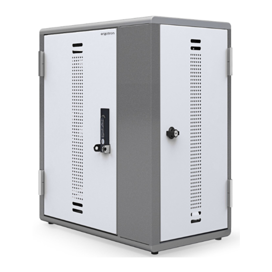
This Cabinet is designed to automatically charge and store tablet, smart phone, and hand-held devices safely and effi ciently. This
cabinet supports 1-20 devices. Please review this manual before installing your equipment to learn how to use the cabinet safely.
The cabinet is listed to UL 62368 Audio/Video Information and Communication Technology Equipment. CAN/CSA C22.2 No. 62368-1
AC input: 120VAC 60 Hz. Max amps: 12A.
For the latest User Installation Guide please visit: www.ergotron.com
English, Français
888-83-090-G-00 rev. C • 11/19
YES20
Charging Cabinet for Tablets
User's Guide
www.ergotron.com |
USA: 1-800-888-8458
English
1 of 22
Advertisement

Subscribe to Our Youtube Channel
Related Manuals for Ergotron YES20


Summary of Contents for Ergotron YES20
- Page 1 The cabinet is listed to UL 62368 Audio/Video Information and Communication Technology Equipment. CAN/CSA C22.2 No. 62368-1 AC input: 120VAC 60 Hz. Max amps: 12A. English For the latest User Installation Guide please visit: www.ergotron.com English, Français www.ergotron.com | USA: 1-800-888-8458 1 of 22 888-83-090-G-00 rev.
- Page 2 Liquids should not be stored in, set on or placed inside this unit. Never unplug this product from the outlet when your hands are wet. Ergotron does not accept any liability for damage if the unit is misused, incorrectly operated or inadequately repaired. Under these circumstances the warranty will be void.
-
Page 3: Safe Use Recommendations
Safe Use Recommendations WARNING: Failure to observe the following Safety notices may result in serious personal injury or equipment damage. WARNING: Death or serious injury may occur when children climb on audio and/or video equipment furniture. A remote control or toys placed on the furnishing may encourage a child to climb on the furnishing and as a result the furnishing may tip over on to the child. -
Page 4: Features And Specifications
Features & Specifi cations 1. Feet (for countertop installation) 2. Locking front door to user area with latch and padlock bracket For added security, each door 3. Locking side door to IT area features hasps to hold your own padlock (maximum shackle 4. - Page 5 Components #10-12 x 1.5" 4 mm 1/4-20 x 2" #10 x 3/4" M6 x 90 mm Tools Needed 10 mm Stud Finder COUNTER TOP WOOD HOLLOW WALL 16” (406 mm) 16” (406 mm) Ø 6 mm (1/4") Ø 1/8" (3 mm) Ø...
- Page 6 Open doors. 6 of 22 888-83-090-G-00 rev. C • 11/19...
- Page 7 COUNTER TOP WOOD 16” (406 mm) HOLLOW WALL 16” (406 mm) 7 of 22 888-83-090-G-00 rev. C • 11/19...
- Page 8 COUNTER TOP #10 x 3/4" 4 mm Slice through the membrane covering Mark Holes. the predrilled holes. 8 of 22 888-83-090-G-00 rev. C • 11/19...
- Page 9 COUNTER TOP Ø 6 mm (1/4") M6 x 90 mm 4 mm 10 mm CONTINUE WITH INSTALLATION ON PAGE: 16 9 of 22 888-83-090-G-00 rev. C • 11/19...
- Page 10 WOOD 16” (406 mm) 16” (406 mm) Ø 1/8" (3 mm) #10-12 x 1.5" 10 of 22 888-83-090-G-00 rev. C • 11/19...
- Page 11 WOOD 16” (406 mm) 2 person lift. Ø 1/8" (3 mm) 11 of 22 888-83-090-G-00 rev. C • 11/19...
- Page 12 WOOD 16” (406 mm) 2 person lift. #10-12 x 1.5" CONTINUE WITH INSTALLATION ON PAGE: 16 12 of 22 888-83-090-G-00 rev. C • 11/19...
- Page 13 HOLLOW WALL 16” (406 mm) Ø 1/2" (13 mm) 16” (406 mm) 4 mm 1/4-20 x 2" 13 of 22 888-83-090-G-00 rev. C • 11/19...
- Page 14 HOLLOW WALL 16” (406 mm) 2 person lift. Ø 1/2" (13 mm) 14 of 22 888-83-090-G-00 rev. C • 11/19...
- Page 15 HOLLOW WALL 16” (406 mm) 2 person lift. 4 mm 4 mm 1/4-20 x 2" CONTINUE WITH INSTALLATION ON PAGE: 16 15 of 22 888-83-090-G-00 rev. C • 11/19...
- Page 16 Route cables. 16 of 22 888-83-090-G-00 rev. C • 11/19...
- Page 17 Add the Bay labels to each Bay Plug in and insert devices. Plug in power cord. Turn on. NOTE: ALL DEVICES MUST BE TURNED OFF BEFORE CHARGING. Failure to follow these instructions may result in overheating. To charge devices, plug in power cord and turn power on. 17 of 22 888-83-090-G-00 rev.
- Page 18 How to Adjust Bay Width: Remove Divider Install Divider 18 of 22 888-83-090-G-00 rev. C • 11/19...
- Page 19 How to Adjust Shelf Height: 19 of 22 888-83-090-G-00 rev. C • 11/19...
-
Page 20: Specifications
1) This device may not cause harmful interference. 2) This device must accept any interference received, including interference that may cause undesired operation. Changes or modifi cations not expressly approved by Ergotron could void the user's authority to operate the equipment. Intended for institutional use. -
Page 21: Cleaning And Maintenance
WARNING: Do not use fl ammable cleaners on surfaces. CAUTION: Adjustment, Service, Replacement - DO NOT attempt to adjust, service or replace any part unless directed to do so through Ergotron-approved documentation (i.e. installation instructions). Only Ergotron, Inc. or an Ergotron-certifi ed entity may adjust, service or replace components. If any component is missing or damaged, this must not be used. - Page 22 For Warranty visit: www.ergotron.com/warranty For Service visit: www.ergotron.com For local customer care phone numbers visit: http://contact.ergotron.com NOTE: When contacting customer service, reference the serial number. www.ergotron.com | USA: 1-800-888-8458 © 2019 Ergotron, Inc. All rights reserved. 22 of 22 888-83-090-G-00 rev. C • 11/19...
Need help?
Do you have a question about the YES20 and is the answer not in the manual?
Questions and answers