Advertisement
Quick Links
MIC-75G20
GPU card Expansion i-Module for MIC-7 Series
Embedded System
Startup Manual
Packing List
Before you begin installing your i-Module, please make
sure that the following items have been shipped:
1. MIC-75G20 i-Module x1
2. 4-pin phoenix connector x2
3. SATA cable (30cm) x1
4. SATA cable (40cm) x1
5. HDD BP power cable x1
6. GPU power cable
(6 to 6/8 Pin) x2
7. Mounting bracket (I-type) x1
8. Mounting bracket (C-type) x1
9. Screw for mounting bracket x4
10. MIC-75G20 Start-up manual x1 P/N: 20415G2000
If any of these items are missing or damaged, please
contact your distributor or sales representative immediately.
Note:
Acrobat Reader is required to view any PDF
file. Acrobat Reader can be downloaded at: get.
adobe.com/reader (Acrobat is a trademark of
Adobe)
Specifications
PCIe Slots
• One PCIe x16 socket
• One PCIe x4 socket
For more information on this and other Advantech
products, please visit our website at:
http://www.advantech.com
http://www.advantech.com/eplatform
For technical support and service, please visit our
support website at:
This manual is for the MIC-75G20 Rev. A1.
Part No. 20415G2000
Printed in China
P/N: MIC-75G20-00A1
P/N: 1652003234
P/N: 1700017838
P/N: 1700020978-01
P/N: 1700024985-01
P/N: 1700023022-01
P/N: 1960070543T001
P/N: 1960070545N001
PN: 1930007259-01
1st Edition
December 2018
Specifications (Cont.)
Environment
• Operating Temperature:
0 ~ 40° C with 0.7 m/sec air flow: with Industrial SSD
• Storage Temperature: - 40 ~ 85° C (-40 ~185° F)
• Relative Humidity: 95% @ 40° C (non-condensing)
Mechanical
• i-Module Dimensions: i-Module Dimension (W x H x D):
110 x 192 x 350 mm
• With MIC-7 series: With MIC-7 series (W x H x D): 183 x
192 x 350 mm
Note: Width will be increased by 4mm with MIC-77xx.
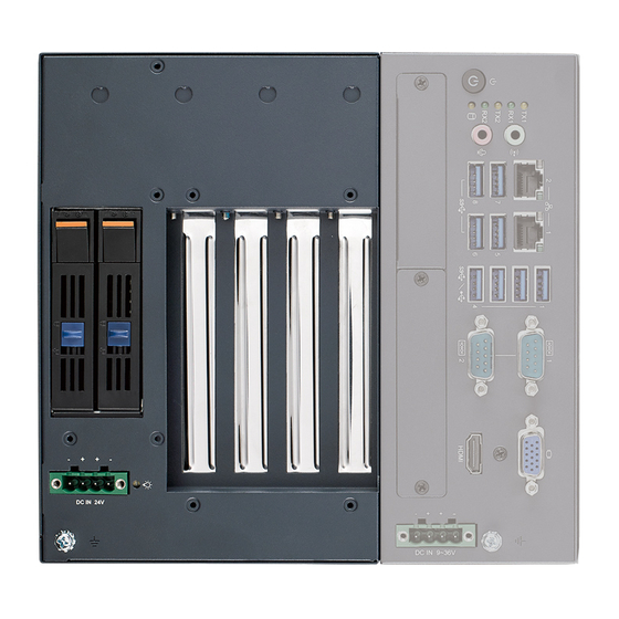
I/O Connectors
Connectors
No.
Item
Function
1
DCIN1
24VDC in
2
PPCIE2
PCIe x16 slot
3
PPCIE1
PCIe x4 slot
4
SATAPWR1
4-pin SATA power connector (5V)
5
SATA1
SATA signal connector
6-pin power connector for GPU
6
GPUPWR1
card (12V, 17A)
6-pin power connector for GPU
7
GPUPWR2
card (12V, 17A)
DC12VO-
8
4-pin power connector (12V, 5A)
OUT1
9
SYSFAN1
4-pin fan connector
10
SYSFAN2
4-pin fan connector (reserved)
11
LED
GPU card power status
24VDC -IN
PCIe x16
GPU PWR LED
PCIe x4
MIC-75G20 Startup Manual 1
GPU PWR1
GPU PWR 2
DC 12V PWR
Fan1 Conn.
Fan2 Conn.
SATA power
SATA signal
Advertisement

Related Manuals for Advantech MIC-75G20


Summary of Contents for Advantech MIC-75G20
- Page 1 24VDC -IN PCIe x16 DC 12V PWR Fan1 Conn. Fan2 Conn. SATA power SATA signal This manual is for the MIC-75G20 Rev. A1. GPU PWR LED Part No. 20415G2000 1st Edition December 2018 Printed in China PCIe x4 MIC-75G20 Startup Manual 1...
- Page 2 1. Undo MIC-7 series system screws and remove the bottom cover. 2. Remove 2 x dust covers (IMPORTANT!). 5. Align MIC-75G20 and MIC-7 and secure 4 x screws. 3. Undo the 4 x screws on MIC-75G20. 6. Assemble MIC-75G20 cover and secure with 6 x screws.
- Page 3 Simple Maintenace Process (Cont.) Fan filter Replacement Note: MIC-75G20 has 2 bolts which must be aligned Recommend to replace fan filter at regular internals to with the holes on the device. ensure the stability of system cooling. 1. Undo the system cover and remove the old fan filter.
- Page 4 2. Type 2: Secure 2 x mounting brackets (1960070543T001) with 4 x screws (1930007259-01) (There are 2x 1960070543T001 in the accessory box of MIC-7 series.) Type 2 Type 1 System Dimensions Type 1 Type 2 5.20 * Width is 187mm with MIC-77xx installed. 4 MIC-75G20 Startup Manual...
Need help?
Do you have a question about the MIC-75G20 and is the answer not in the manual?
Questions and answers